


 Loading...
Table of Contents
All-Flex Mowers
AFM4211
19628
315-507M
Operator’s Manual
! |
Read the Operator’s manual entirely. When |
|
you see this symbol, the subsequent |
||
instructions and warnings are serious - follow |
||
|
without exception. Your life and the lives of |
|
|
others depend on it! |
|
|
© Copyright 2008 Pr inted |
11/14/08 |
Cover photo may show optional equipment not supplied with standard unit.

Table of Contents
Important Safety Information . . . . . . . . . . .1
Safety at All Times . . . . . . . . . . . . . . . . . . . . . . . . . 1
Look For The Safety Alert Symbol . . . . . . . . . . . . . 1
Safety Labels . . . . . . . . . . . . . . . . . . . . . . . . . . . . . 4
Introduction . . . . . . . . . . . . . . . . . . . . . . .11
Application . . . . . . . . . . . . . . . . . . . . . . . . . . . . . . 11
Using This Manual . . . . . . . . . . . . . . . . . . . . . . . . 11
Terminology . . . . . . . . . . . . . . . . . . . . . . . . . . 11
Definitions . . . . . . . . . . . . . . . . . . . . . . . . . . . . 11
Owner Assistance . . . . . . . . . . . . . . . . . . . . . . . . 11
Serial Number Plate . . . . . . . . . . . . . . . . . . . . 11
Further Assistance . . . . . . . . . . . . . . . . . . . . . 11
Section 1: Assembly and Set-up . . . . . .12
Tractor Requirements . . . . . . . . . . . . . . . . . . . . . 12
Hardware Torque Information . . . . . . . . . . . . . . . 12
PTO To Drawbar Set-Up . . . . . . . . . . . . . . . . . . . 12
Tractor Hook-up . . . . . . . . . . . . . . . . . . . . . . . . . . 12
Main Driveline Installation . . . . . . . . . . . . . . . . . . 13
Hydraulic Hook-up . . . . . . . . . . . . . . . . . . . . . . . . 14
Pull Rope Hook-up . . . . . . . . . . . . . . . . . . . . . . . . 14
Gauge Wheel Assembly . . . . . . . . . . . . . . . . . . . 14
Bleeding Hydraulics . . . . . . . . . . . . . . . . . . . . . . . 15
Section 2: Operating Instructions . . . . .16
Introduction . . . . . . . . . . . . . . . . . . . . . . . . . . . . . 16
U-Joint Timing . . . . . . . . . . . . . . . . . . . . . . . . . . . 16
Transporting . . . . . . . . . . . . . . . . . . . . . . . . . . . . 16
Constant Velocity Driveline Angle . . . . . . . . . . . . 17
Pre-Operation Instructions . . . . . . . . . . . . . . . . . . 17
Operating Instructions . . . . . . . . . . . . . . . . . . . . . 18
General Operating Instructions . . . . . . . . . . . . . . 19
Section 3: Adjustments . . . . . . . . . . . . . .20
Center Deck Height Adjustments . . . . . . . . . . . . . 20
Belt Tension . . . . . . . . . . . . . . . . . . . . . . . . . . . . . 21
Section 4: Accessories . . . . . . . . . . . . . .22
Ball Swivel Hitch . . . . . . . . . . . . . . . . . . . . . . . . . 22
Cutting Blades . . . . . . . . . . . . . . . . . . . . . . . . . . . 22
Low Lift Blades . . . . . . . . . . . . . . . . . . . . . . . . 22
Medium Lift Blades . . . . . . . . . . . . . . . . . . . . . 22
High Lift Blades . . . . . . . . . . . . . . . . . . . . . . . . 22
Mulching Blades . . . . . . . . . . . . . . . . . . . . . . . 22
© Copyright 2008 All rights Reserved
Section 5: Maintenance and Lubrication 23
Maintenance . . . . . . . . . . . . . . . . . . . . . . . . . . . . 23
Servicing Mower Blades . . . . . . . . . . . . . . . . . . . . 23
Blade Inspection . . . . . . . . . . . . . . . . . . . . . . . 23
Blade Removal And Installation . . . . . . . . . . . . 24
Blade Sharpening . . . . . . . . . . . . . . . . . . . . . . 25
Blade Options: . . . . . . . . . . . . . . . . . . . . . . . . . 25
V-Belt Installation . . . . . . . . . . . . . . . . . . . . . . 25
Driveline Protection . . . . . . . . . . . . . . . . . . . . . . . 26
Type A Clutches . . . . . . . . . . . . . . . . . . . . . . . 26
Type B Clutch . . . . . . . . . . . . . . . . . . . . . . . . . 28
Storage . . . . . . . . . . . . . . . . . . . . . . . . . . . . . . . . 29
Tires With Air Pressure . . . . . . . . . . . . . . . . . . . . 29
Lubrication . . . . . . . . . . . . . . . . . . . . . . . . . . . . . . 30
Driveline Constant Velocity Shaft . . . . . . . . . . 30
Driveline Shafts . . . . . . . . . . . . . . . . . . . . . . . . 30
Inner Tube of Driveline . . . . . . . . . . . . . . . . . . 30
Wheel Support Bushings . . . . . . . . . . . . . . . . . 31
Wheel Bushings (Gauge Wheels) . . . . . . . . . . 31
Wheel Bushings (Transport Hubs) . . . . . . . . . . 31
Blade Spindle Bearings, Center Deck . . . . . . . 31
4-Way Gearbox . . . . . . . . . . . . . . . . . . . . . . . . 32
Mower Deck Gearbox . . . . . . . . . . . . . . . . . . . 32
Blade Spindle Bearings, Wing Decks . . . . . . . 32
Tool Bar To Floating Link Pivot Pin . . . . . . . . . 32
Transport Locks . . . . . . . . . . . . . . . . . . . . . . . . 33
Wing Deck Pivot Bushings . . . . . . . . . . . . . . . 33
Rear Deck Pivot Half Clamps . . . . . . . . . . . . . 33
Wing Flex Pivot Lugs . . . . . . . . . . . . . . . . . . . . 33
Section 6: Specifications & Capacities .34
Section 7: Features and Benefits . . . . . .36
Section 8: Troubleshooting . . . . . . . . . .37
Section 9: Appendix . . . . . . . . . . . . . . . .39
Torque Values Chart . . . . . . . . . . . . . . . . . . . . . . 39
Tire Inflation Chart . . . . . . . . . . . . . . . . . . . . . . . . 39
Notes . . . . . . . . . . . . . . . . . . . . . . . . . . . . . . . . . . 40
Warranty . . . . . . . . . . . . . . . . . . . . . . . . . . . . . . . 41
Land Pride provides this publication “as is” without warranty of any kind, either expressed or implied. While every precaution has been taken in the preparation of this manual, Land Pride assumes no responsibility for errors or omissions. Neither is any liability assumed for damages resulting from the use of the information contained herein. Land Pride reserves the right to revise and improve its products as it sees fit. This publication describes the state of this product at the time of its publication, and may not reflect the product in the future.
Land Pride is a registered trademark.
All other brands and product names are trademarks or registered trademarks of their respective holders.
Printed in the United States of America.
AFM4211 All-Flex Mowers 315-507M |
11/14/08 |
Land Pride |
Table of Contents |
Important Safety Information
These are common practices that may or may not be applicable to the products described in this manual.
Safety at All Times
Thoroughly read and understand the instructions given in this manual before operation. Refer to the “Safety Label” section, read all instructions noted on them.
Do not allow anyone to operate this equipment who has not fully read and comprehended this manual and who has not been properly trained in the safe operation of the equipment.
▲Operator should be familiar with all functions of the unit.
▲Operate implement from the driver’s seat only.
▲Make sure all guards and shields are in place and secured before operating implement.
▲Do not leave tractor or implement unattended with engine running.
▲Dismounting from a moving tractor could cause serious injury or death.
▲Do not allow anyone to stand between the tractor and implement while backing up to the implement.
▲Keep hands, feet, and clothing away from power-driven parts.
▲Wear snug fitting clothing to avoid entanglement with moving parts.
▲Watch out for wires, trees, etc., when raising implement. Make sure all persons are clear of working area.
▲Turning tractor too tight may cause implement to ride up on wheels. This could result in injury or equipment damage.
▲Do not carry passengers on implement at any time.
Look For The Safety Alert Symbol
The SAFETY ALERT SYMBOL indicates there is a
!safety precaution must be taken. When you see this symbol, be alert and carefully read the message that follows it. In addition to design and configuration of equipment, hazard control and accident prevention are dependent upon the awareness, concern, prudence and proper training of personnel involved in
the operation, transport, maintenance and storage of equipment.potential hazard to personal safety involved and extra
Be Aware of
Signal Words
A Signal word designates a degree or level of hazard seriousness. The signal words are:
! DANGER
Indicates an imminently hazardous situation which, if not avoided, will result in death or serious injury. This signal word is limited to the most extreme situations, typically for machine components that, for functional purposes, cannot be guarded.
! WARNING
Indicates a potentially hazardous situation which, if not avoided, could result in death or serious injury, and includes hazards that are exposed when guards are removed. It may also be used to alert against unsafe practices.
! CAUTION
Indicates a potentially hazardous situation which, if not avoided, may result in minor or moderate injury. It may also be used to alert against unsafe practices.
For Your Protection
▲Thoroughly read and understand the “Safety Label” section, read all instructions noted on them.
Shutdown and Storage
▲Lower machine to ground, put tractor in park, turn off engine, and remove the key.
▲Detach and store implements in a area where children normally do not play. Secure implement by using blocks and supports.
OFF
REMOVE 
11/14/08 |
AFM4211 All-Flex Mowers 315-507M |
1 |
Table of Contents
Important Safety Information
Land Pride
These are common practices that may or may not be applicable to the products described in this manual.
Use Safety
Lights and Devices
▲Slow moving tractors, selfpropelled equipment, and towed implements can create a hazard when driven on public roads. They are difficult to see, especially at night.
▲Flashing warning lights and turn signals are recommended whenever driving on public roads.
Transport
Machinery Safely
▲Comply with state and local laws.
▲Maximum transport speed for implement is 20 mph. DO NOT EXCEED. Never travel at a speed which does not allow adequate control of steering and stopping. Some rough terrains require a slower speed.
▲Sudden breaking can cause a towed load to swerve and upset. Reduce speed if towed load is not equipped with breaks.
▲Use the following maximum speed - tow load weight ratios as a guideline:
20 mph when weight is less than or equal to the weight of tractor.
10 mph when weight is double the weight of tractor.
▲IMPORTANT: Do not tow a load that is more than double the weight of tractor.
Use A Safety Chain
▲A safety chain will help control drawn machinery should it separate from the tractor drawbar.
▲Use a chain with the strength rating equal to or greater than the gross weight of the towed machinery.
▲Attach the chain to the tractor drawbar support or other specified anchor location. Allow only enough slack in the chain to permit turning.
▲Do not use safety chain for towing.
Practice Safe
Maintenance
▲Understand procedure before doing work. Use proper tools and equipment, refer to Operator’s Manual for additional information.
▲Work in a clean dry area.
▲Lower the implement to the ground, put tractor in park, turn off engine, and remove key before performing maintenance.
▲Allow implement to cool completely.
▲Do not grease or oil implement while it is in operation.
▲Inspect all parts. Make sure parts are in good condition & installed properly.
▲Remove buildup of grease, oil or debris.
▲Remove all tools and unused parts from implement before operation.
|
|
|
|
|
|
|
|
|
|
|
|
|
|
|
|
|
|
|
|
|
|
|
|
|
|
|
|
|
|
|
|
|
|
|
|
|
|
|
|
|
|
|
|
|
|
|
|
|
|
|
|
|
|
|
|
|
|
|
|
|
|
|
|
|
|
|
|
|
|
|
|
|
|
|
|
|
|
|
|
2 |
AFM4211 All-Flex Mowers 315-507M |
11/14/08 |
|||||||||||||
Land Pride |
Table of Contents |
Important Safety Information
These are common practices that may or may not be applicable to the products described in this manual.
Prepare for Emergencies
▲Be prepared if a fire starts.
▲Keep a first aid kit and fire extinguisher handy.
▲Keep emergency numbers for doctor, ambulance, hospital and fire department near phone.
911
Tire Safety
▲Tire changing can be dangerous and should be performed by trained personnel using the correct tools and equipment.
▲When inflating tires, use a clip-on chuck and extension hose long enough to allow you to stand to one side and NOT in front of or over the tire assembly. Use a safety cage if available.
▲When removing and installing wheels, use wheel handling equipment adequate for the weight involved.
Wear
Protective Equipment
▲Protective clothing and equipment should be worn.
▲Wear clothing and equipment appropriate for the job. Avoid loose fitting clothing.
▲Prolonged exposure to loud noise can cause hearing impairment or hearing loss. Wear suitable hearing protection such as earmuffs or earplugs.
▲Operating equipment safely requires the full attention of the operator. Avoid wearing radio headphones while operating machinery.
Avoid High
Pressure Fluids Hazard
▲Escaping fluid under pressure can penetrate the skin causing serious injury.
▲Avoid the hazard by relieving pressure before disconnecting hydraulic lines or performing work on the system.
▲Make sure all hydraulic fluid connections are tight and all hydraulic hoses and lines are in good condition before applying pressure to the system.
▲Use a piece of paper or cardboard, NOT BODY PARTS, to check for suspected leaks.
▲Wear protective gloves and safety glasses or goggles when working with hydraulic systems.
▲If an accident occurs, see a doctor immediately. Any fluid injected into the skin must be treated within a few hours or gangrene may result.
Keep Riders
Off Machinery
▲Riders obstruct the operator’s view, they could be struck by foreign objects or thrown from the machine.
▲Never allow children to operate equipment.
11/14/08 |
AFM4211 All-Flex Mowers 315-507M |
3 |
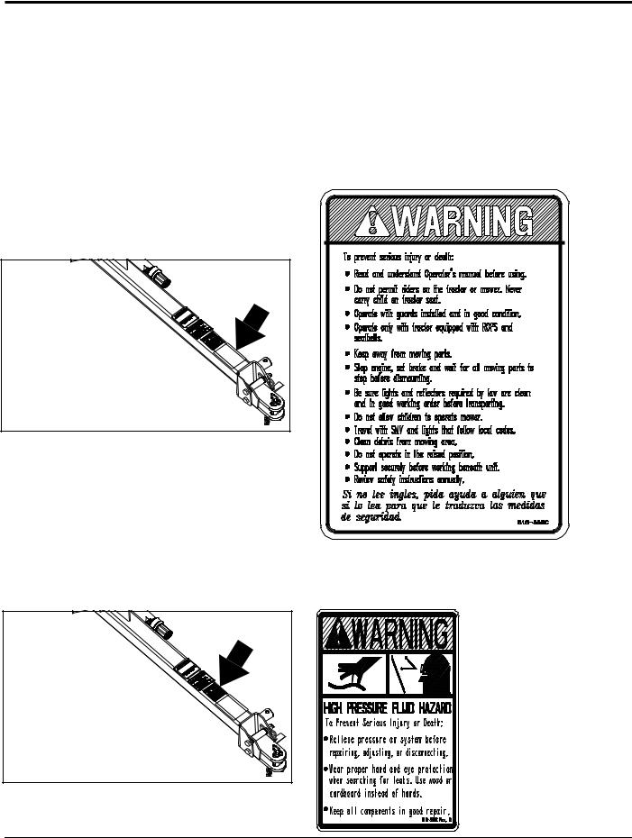
Table of Contents
Important Safety Information
Land Pride
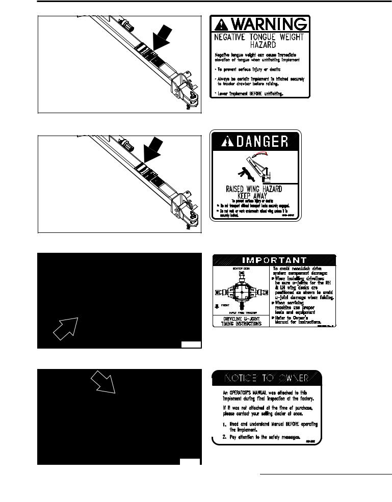
Safety Labels
Your mower comes equipped with all safety labels in place. They were designed to help you safely operate your implement. Read and follow their directions.
1.Keep all safety labels clean and legible.
2.Replace all damaged or missing labels. To order new labels go to your nearest Land Pride dealer or visit our dealer locator at landpride.com.
3.Some new equipment installed during repair requires safety labels to be affixed to the replaced component as
specified by Land Pride. When ordering new components make sure the correct safety labels are included in the request.
4.Refer to this section for proper label placement. To install new labels:
a.Clean the area the label is to be placed.
b.Spray soapy water on the surface where the label is to be placed.
c.Peel backing from label. Press firmly onto the surface.
d.Squeeze out air bubbles with the edge of a credit card.
26884 |
818-558C |
Warning: Serious Injury
26884 |
818-339C |
|
Warning: High Pressure
4 |
AFM4211 All-Flex Mowers 315-507M |
11/14/08 |
Land Pride |
Table of Contents |
Important Safety Information
26884 |
818-019C

 Warning:
Negative Tongue Weight
818-561C
Danger: Raised Wing
26884 |
|
|
|
|
|
|
818-565C |
|
|
|
26884 |
Important: U-Joint Timing Instructions |
|
|
|
|
|
|
|
|
|
818-560C |
|
|
|
26884 |
Notice: Manual Info. |
|
|
|
|
|
|
|
11/14/08 |
|
AFM4211 All-Flex Mowers |
315-507M |
5 |
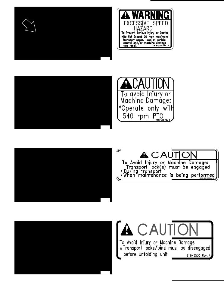
Table of Contents
Important Safety Information
Land Pride
818-337C
26884
Warning: Max Trans Speed
818-130C
26884
Caution: 540 RPM
|
|
|
818-351C |
|
|
26884 |
Caution: Lock For Transport |
|
|
|
818-353C |
|
|
26884 |
Caution: Unlock To Unfold |
|
|
|
|
6 |
AFM4211 All-Flex Mowers |
315-507M |
11/14/08 |
Land Pride |
Table of Contents |
Important Safety Information
|
ROTATING DRIVELINE |
|
KEEP AWAY! |
26884 |
|
1960 |
818-556C |
|
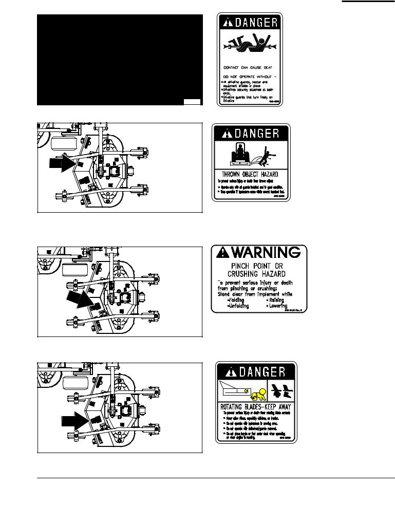
818-552C
Danger: Entanglement
Danger: Thrown Object Hazard
Location: (3-Places) On Back of All Three Decks
818-045C
1960 Warning: Pinch point or Crushing Hazard Location: (3-Places) On Back of All Three Decks
1960 818-555C
Danger: Rotating Blade
Location: (3-Places) On Back of All Three Decks
11/14/08 |
AFM4211 All-Flex Mowers 315-507M |
7 |
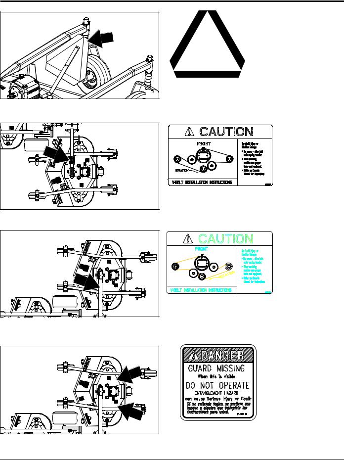
Table of Contents
Important Safety Information
Land Pride
1960 |
1960 |
1960 |
1960 |
818-003C
Slow Moving Vehicle Label
Location: On Back of Center Deck Only
838-345C
Caution: V-Belt Installation
Right Hand & Center Deck (Beneath Belt Guard)
838-270C
Caution: V-Belt Installation:
Left Hand Deck (Beneath Belt Guard)
818-543C
Danger: Guard Missing Location: (6-Places)
Beneath Both Guards on All Three Decks
8 |
AFM4211 All-Flex Mowers 315-507M |
11/14/08 |
Land Pride |
Table of Contents |
Important Safety Information
1365 |
0818-187C
Danger: Shield Missing
818-229C
Amber Reflector:
(Right Hand Shown Left Hand Opposite)
1960
1960 |
818-230C
Red Reflector:
(Right Hand Shown Left Hand Opposite)
|
818-230C |
|
|
|
Red Reflector: |
|
|
|
(Center Deck) |
|
|
|
1960 |
|
|
11/14/08 |
AFM4211 All-Flex Mowers |
315-507M |
9 |
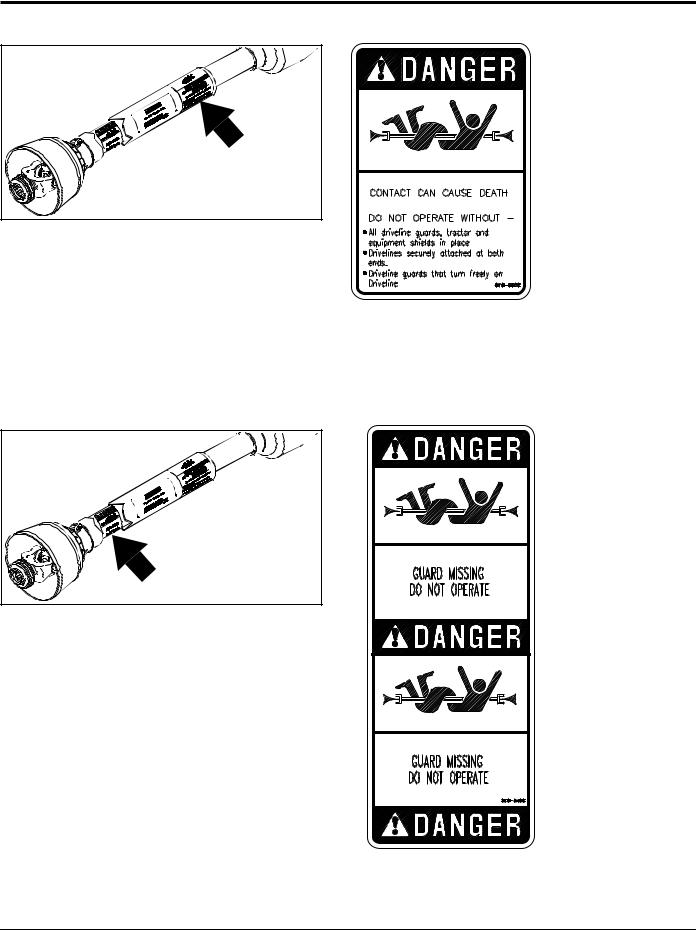
Table of Contents
Important Safety Information
Land Pride
1331 |
1331 |
ROTATING DRIVELINE |
|
KEEP AWAY! |
818-552C |
|
Danger: Entanglement
818-540C
Danger: Guard Missing
10 AFM4211 All-Flex Mowers 315-507M |
11/14/08 |
Land Pride
Introduction
Table of Contents
Land Pride welcomes you to the growing family of new product owners.
This All-Flex Mower has been designed with care and built by skilled workers using quality materials. Proper assembly, maintenance, and safe operating practices will help you get years of satisfactory use from the machine.
Application
The AFM4211 All-Flex Mower is designed and built by Land Pride to provide excellent cutting quality and performance on lush type turf grasses on expansive and well manicured areas such as fairways, parks, school lawns, sports fields, and 5 acre estates.
The AFM4211 requires attachment to a 30-65 hp turf tractor with 540 rpm PTO speed and can be ordered with slip-clutch or conventional wing driveline configurations.
The mower offers independent deck flotation and zero turning radius due to the sleek frame design. When you need to transport from one mowing site to another the hydraulic wing cylinders will easily lift up the wing decks for a 5’-6" transport width. The contour following capability, highly productive 11’ cutting width, and rear discharge design of the floating cutting decks will greatly reduce wide-area cutting times and still deliver finely groomed surfaces at mowing speeds from 2-6 mph.
See “Section 6: Specifications & Capacities” and “Section 7: Features and Benefits” for additional information and performance enhancing options.
Using This Manual
•This Operator’s Manual is designed to help familiarize you with safety, assembly, operation, adjustments, troubleshooting, and maintenance. Read this manual and follow the recommendations to help ensure safe and efficient operation.
•The information contained within this manual was current at the time of printing. Some parts may change slightly to assure you of the best performance.
•To order a new Operator’s or Parts Manual contact your authorized dealer. Manuals can also be downloaded, free-of-charge from our website at www.landpride.com.
Terminology
“Right” or “Left” as used in this manual is determined by facing the direction the machine will operate while in use unless otherwise stated.
Owner Assistance
The Warranty Registration card should be filled out by the dealer at the time of purchase. This information is necessary to provide you with quality customer service.
If customer service or repair parts are required contact a Land Pride dealer. A dealer has trained personnel, repair parts and equipment needed to service the implement.
The parts on your AFM4211 All-Flex Mower have been specially designed and should only be replaced with genuine Land Pride parts. Therefore, should your Mower require replacement parts go to your Land Pride Dealer.
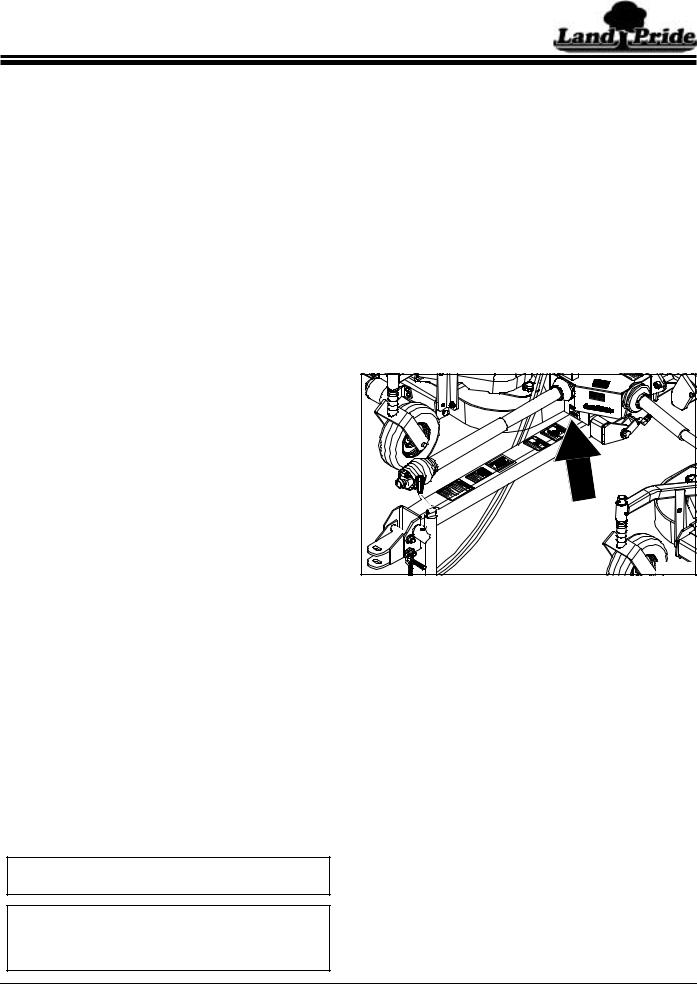
Serial Number Plate
For prompt service always use the serial number and model number when ordering parts from your Land Pride dealer. Be sure to include your serial and model numbers in correspondence also. Refer to Figure 1 for the location of your serial number plate.
18752 |
Serial Number Plate Location
Figure 1
Further Assistance
Your dealer wants you to be satisfied with your new All-Flex Mower. If for any reason you do not understand any part of this manual or are not satisfied with the service received, the following actions are suggested:
1.Discuss the matter with your dealership service manager making sure he is aware of any problems you may have and that he has had the opportunity to assist you.
2.If you are still not satisfied, seek out the owner or general manager of the dealership, explain the problem and request assistance.
3.For further assistance write to:
Definitions
NOTE: A special point of information that the operator must be aware of before continuing.
IMPORTANT: A special point of information related to its preceding topic. Land Pride’s intention is that this information should be read and noted before continuing.
Land Pride
Service Department
P.O. Box 5060
Salina, KS 67402-5060
E-Mail lpservicedept@landpride.com
11/14/08 |
AFM4211 All-Flex Mowers 315-507M |
11 |
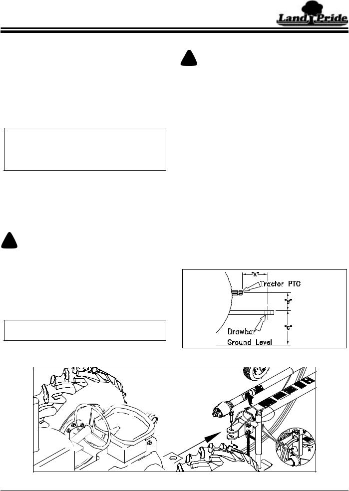
Table of Contents
Section 1: Assembly and Set-up
Tractor Requirements
Tractor horsepower should be within the range noted below. Tractors outside the horsepower range must not be used.
Horsepower Rating. . . . . . . . . . . . . . . . . . . 30-65 HP Rear PTO Shaft Type . . . . . . . . . . . . . 1 3/8”-6 Spline Rear PTO Speed . . . . . . . . . . . . . . . . . . . . 540 RPM Hitch Type . . . . . . . . . . . . . . . . . . . . . . . . . .Draw Bar Hydraulic Outlets . . . . . . . . . . . . . One Duplex Outlet Tractor Weight . . . . . . . . . See Important Note Below
IMPORTANT: Ballast may need to be added to your tractor to maintain steering control. Refer to your tractor’s operator manual to determine if additional ballast is needed. This mower has a positive transport tongue weight of approximately 500 lbs.
Hardware Torque Information
When tightening hardware, refer to “Torque Values Chart” on page 39 to determine standard torque values. Refer to "Additional Torque Values" at the bottom of the chart for exceptions to the standard torque values.
PTO To Drawbar Set-Up
! CAUTION!
Do not over speed PTO or machine damage may result. This mower is designed to be used with a tractor using a rear 540 rpm PTO drive.
Refer to Figure 1-1:
Distances between center of drawbar hitch pin hole to end of tractor PTO shaft (“A” dimension) and from top of drawbar hitch to center of PTO shaft (“B” dimension) must be maintained.
IMPORTANT: PTO damage may occur if distances “A” and “B” are not properly maintained.
Tractor Hook-up
! DANGER!
Crushing Hazard between tractor and implement. Do not allow anyone to stand between the tractor and implement while backing-up to an implement. Never operate the hydraulic 3-point lift controls while someone is directly behind the tractor.
Refer to Refer to Figure 1-2:
1.Make certain jack stand is properly attached to the mower hitch and secured with attachment pin.
2.Back tractor within close proximity of clevis.
3.Raise or lower jack stand to align clevis with tractor drawbar. Drawbar should fit between lower and upper plates of clevis.
4.Back tractor up to mower hitch until holes in drawbar and clevis are aligned.
5.Attach mower with a 3/4" hitch pin and secure with lock pin. Always use a hitch pin that contains a safety locking device to prevent it from falling out.
6.Retract jack stand until weight of mower is fully removed from the jack. Remove jack and store on storage tube located on divider gearbox shield.
7.Attach safety chain on the frame tongue to the tractor. Adjust chain length to remove all slack except what is necessary to permit turning of mower. Lock chain hook securely onto the chain.
= 14”
= 8”
2227
PTO to Drawbar Distances
Figure 1-1 |
14918 |
Mower to Tractor Hook-up
Figure 1-2
12 AFM4211 All-Flex Mowers 315-507M |
11/14/08 |
Loading...