


 Loading...
Kurzweil PC2R
Musician’s Guide
©2000 All rights reserved. Kurzweil is a product line of Young Chang Co.; Kurzweil and PC2R are trademarks of Young Chang Co. All other products and brand names are trademarks or registered trademarks of their respective companies. Product features and specifications are subject to change without notice.
Part Number: 910350 Rev. A November 1, 2000

The symbol of a house with |
|
an arrow pointing inside |
|
is intended to alert the user |
|
that the product is to |
|
be used indoors only. |
! |
The exclamation point within an equilateral triangle is intended to alert the user to the presence of important operating and maintenance (servicing) instructions in the literature accompanying the product.
IMPORTANT SAFETY & INSTALLATION INSTRUCTIONS
INSTRUCTIONS PERTAINING TO THE RISK OF FIRE, ELECTRIC SHOCK, OR INJURY TO PERSONS
WARNING: When using electric products, basic precautions should always be followed, including the following:
1.Read all of the Safety and Installation Instructions and Explanation of Graphic Symbols before using the product.
2.Do not use this product near water—for example, near a bathtub, washbowl, kitchen sink, in a wet basement, or near a swimming pool, or the like.
3.This product should be used only with a stand or cart that is recommended by the manufacturer.
4.This product, either alone or in combination with an amplifier and speakers or headphones, may be capable of producing sound levels that could cause permanent hearing loss. Do not operate for a long period of time at a high volume level or at a level that is uncomfortable. If you experience any hearing loss or ringing in the ears, you should consult an audiologist.
5.The product should be located so that its location or position does not interfere with its proper ventilation.
6.The product should be located away from heat sources such as radiators, heat registers, or other products that produce heat.
7.The product should be connected to a power supply only of the type described in the operating instructions or as marked on the product.
8.This product may be equipped with a polarized line plug (one blade wider than the other). This is a safety feature. If you are unable to insert the plug into the outlet, contact an electrician to replace your obsolete outlet. Do not defeat the safety purpose of the plug.
9.The power supply cord of the product should be unplugged from the outlet when left unused for a long period of time. When unplugging the power supply cord, do not pull on the cord, but grasp it by the plug.
10.Care should be taken so that objects do not fall and liquids are not spilled into the enclosure through openings.
11.The product should be serviced by qualified service personnel when:
A.The power supply cord or the plug has been damaged;
B.Objects have fallen onto, or liquid has been spilled into the product;
C.The product has been exposed to rain;
D.The product does not appear to be operating normally or exhibits a marked change in performance;
E.The product has been dropped, or the enclosure damaged.
12.Do not attempt to service the product beyond that described in the user maintenance instructions. All other servicing should be referred to qualified service personnel.
13.WARNING: Do not place objects on the product’s power supply cord, or place the product in a position where anyone could trip over, walk on, or roll anything over cords of any type. Do not allow the product to rest on or be installed over cords of any type. Improper installations of this type create the possibility of a fire hazard and/or personal injury.
RADIO AND TELEVISION INTERFERENCE
WARNING: Changes or modifications to this instrument not expressly approved by Young Chang could void your authority to operate the instrument.
IMPORTANT: When connecting this product to accessories and/or other equipment use only high quality shielded cables.
NOTE: This instrument has been tested and found to comply with the limits for a Class A digital device, pursuant to Part 15 of the FCC Rules. These limits are designed to provide reasonable protection against harmful interference when the instrument is used in a commercial environment. This instrument generates, uses, and can radiate radio frequency energy and, if not installed and used in accordance with the instruction manual, may cause harmful interference to radio communications. Operation of this instrument in a residential area is likely to cause harmful interference, in which case the user will be required to correct the interference at his or her own expense.
Changes and modifications not expressly approved by the manufacturer
or registrant of this instrument can void the user’s authority to operate this instrument under Federal Communications Commission rules.
In order to maintain compliance with FCC regulations, shielded cables must be used with this instrument. Operation with unapproved equipment or unshielded cables is likely to result in harmful interference to radio and television reception.
NOTICE
This apparatus does not exceed the Class A limits for radio noise emissions from digital apparatus set out in the Radio Interference Regulations of the Canadian Department of Communications.
AVIS
Le present appareil numerique n’emet pas de bruits radioelectriques depassant les limites applicables aux appareils numeriques de la class A prescrites dans le Reglement sur le brouillage radioelectrique edicte par le ministere des Communications du Canada.
SAVE THESE INSTRUCTIONS
ii

Young Chang Distributors
Contact the nearest Young Chang office listed below to locate your local Young Chang/ Kurzweil representative.
Young Chang America, Inc.
P.O. Box 99995
Lakewood, WA 98499-0995
Tel: (253) 589-3200
Fax: (253) 984-0245
Young Chang Co., Ltd.
178-55 Gajwa-Dong
Seo-Ku, Inchon, Korea 404-714
Tel: 011-82-32-570-1380
Fax: 011-82-32-570-1218
Young Chang Akki Europe GmbH
Industriering 45
D-41751 Viersen
Germany
Tel: 011-49-2162-4491
Fax: 011-49-2162-41744
Young Chang America, Inc. (Canadian Division)
3650 Victoria Park Ave. Suite 105
Toronto, Ontario Canada M2H 3P7
Tel: (416) 492-9899
Fax: (416) 492-9299
iii

Contents
Young Chang Distributors ............................................................................................................................................... iii
Chapter 1 Introduction |
|
Basic PC2R Features........................................................................................................................................................ |
1-1 |
The Sound ................................................................................................................................................................. |
1-1 |
Physical Controllers................................................................................................................................................. |
1-1 |
Effects......................................................................................................................................................................... |
1-2 |
Options ............................................................................................................................................................................. |
1-2 |
Sound ROM Cards................................................................................................................................................... |
1-2 |
Polyphony Expansion Board.................................................................................................................................. |
1-2 |
Unpacking your PC2R.................................................................................................................................................... |
1-2 |
Chapter 2 Startup
Setup.................................................................................................................................................................................. |
2-1 |
Basic Connections............................................................................................................................................................ |
2-2 |
Power ......................................................................................................................................................................... |
2-2 |
Audio ......................................................................................................................................................................... |
2-3 |
Digital Output ................................................................................................................................................... |
2-3 |
MIDI........................................................................................................................................................................... |
2-3 |
MIDI Configurations ........................................................................................................................................ |
2-4 |
MIDI Thru/Out................................................................................................................................................. |
2-4 |
Powering Up .................................................................................................................................................................... |
2-4 |
Display (LCD)........................................................................................................................................................... |
2-5 |
LEDs........................................................................................................................................................................... |
2-5 |
Software Upgrades .................................................................................................................................................. |
2-5 |
Playing the Demo Sequences ................................................................................................................................. |
2-5 |
Troubleshooting........................................................................................................................................................ |
2-5 |
No Text in Display ............................................................................................................................................ |
2-5 |
Low Battery........................................................................................................................................................ |
2-5 |
No Sound ........................................................................................................................................................... |
2-6 |
Chapter 3 Playing Your PC2R
Changing Sounds ............................................................................................................................................................ |
3-1 |
Demonstration Sequences.............................................................................................................................................. |
3-1 |
Also In This Chapter....................................................................................................................................................... |
3-1 |
Overview .......................................................................................................................................................................... |
3-2 |
Modes ........................................................................................................................................................................ |
3-2 |
Performance Modes................................................................................................................................................. |
3-2 |
Internal Voices (Programs) .............................................................................................................................. |
3-2 |
KB3 Mode (KB3 Programs) ............................................................................................................................. |
3-2 |
MIDI Setups Mode (Setups) ............................................................................................................................ |
3-2 |
Special Modes........................................................................................................................................................... |
3-3 |
Objects........................................................................................................................................................................ |
3-3 |
EQ............................................................................................................................................................................... |
3-3 |
Effects......................................................................................................................................................................... |
3-4 |
The Front Panel................................................................................................................................................................ |
3-4 |
v

Kurzweil PC2R Musician’s Guide
Contents |
|
Color-Coded Labeling ............................................................................................................................................. |
3-5 |
The Display (LCD) ................................................................................................................................................... |
3-5 |
The Performance Region......................................................................................................................................... |
3-7 |
The Edit Region........................................................................................................................................................ |
3-9 |
The Modes Region .................................................................................................................................................. |
3-11 |
Program and Setup Organization ............................................................................................................................... |
3-12 |
Selecting Programs and Setups ................................................................................................................................... |
3-13 |
EQ .................................................................................................................................................................................... |
3-14 |
Changing the EQ.................................................................................................................................................... |
3-14 |
Using the Controllers on Your MIDI Source ............................................................................................................. |
3-14 |
Effects.............................................................................................................................................................................. |
3-15 |
Controlling Effects ................................................................................................................................................. |
3-15 |
Selecting Effects...................................................................................................................................................... |
3-16 |
Changing the Effects Routing............................................................................................................................... |
3-16 |
Bypassing Effects.................................................................................................................................................... |
3-17 |
Wet/Dry Mix .......................................................................................................................................................... |
3-17 |
Changing the Wet/Dry Mix From the Front Panel.................................................................................... |
3-18 |
Editing Effects......................................................................................................................................................... |
3-18 |
Layering and Splitting.................................................................................................................................................. |
3-18 |
Using AutoSplit for Quick Layers and Splits..................................................................................................... |
3-19 |
How AutoSplit Works ........................................................................................................................................... |
3-19 |
Saving Quick Layers and Splits ........................................................................................................................... |
3-20 |
Changing the AutoSplit Key Without Editing................................................................................................... |
3-20 |
Saving the AutoSplit Key...................................................................................................................................... |
3-21 |
Muting and Soloing ...................................................................................................................................................... |
3-21 |
Muting ..................................................................................................................................................................... |
3-21 |
Soloing ..................................................................................................................................................................... |
3-21 |
Zone-Button LEDs ................................................................................................................................................. |
3-22 |
The AutoSplit Feature............................................................................................................................................ |
3-23 |
Saving the Internal Setup............................................................................................................................................. |
3-23 |
Chapter 4 Programming Your PC2R
Basic Editing Concepts ................................................................................................................................................... |
4-1 |
Overview................................................................................................................................................................... |
4-1 |
Beginning to Edit...................................................................................................................................................... |
4-1 |
Entering an Edit Mode ..................................................................................................................................... |
4-2 |
Finding a Parameter and Changing its Value............................................................................................... |
4-2 |
Naming and Storing ......................................................................................................................................... |
4-3 |
Other Save-Dialog Functions ................................................................................................................................. |
4-4 |
Restoring Factory Effects ................................................................................................................................. |
4-4 |
Deleting Objects ................................................................................................................................................ |
4-4 |
Dumping Objects .............................................................................................................................................. |
4-5 |
Editing Short Cuts: Intuitive Entry....................................................................................................................... |
4-6 |
Short Cuts for Navigating the Controllers Menu......................................................................................... |
4-6 |
Short Cuts for Changing Parameter Values .................................................................................................. |
4-7 |
Other Editing Functions.......................................................................................................................................... |
4-8 |
Comparing ......................................................................................................................................................... |
4-8 |
Copying and Pasting ........................................................................................................................................ |
4-9 |
More About SysEx Dumps .................................................................................................................................... |
4-11 |
SysEx IDs........................................................................................................................................................... |
4-11 |
Dumping the Entire Memory........................................................................................................................ |
4-12 |
vi

|
Kurzweil PC2R Musician’s Guide |
|
Contents |
The Program Editor ...................................................................................................................................................... |
4-12 |
Program Structure.................................................................................................................................................. |
4-12 |
Program Editing Basics ......................................................................................................................................... |
4-12 |
Entering the Program Editor......................................................................................................................... |
4-12 |
The Current Layer........................................................................................................................................... |
4-13 |
Keymaps........................................................................................................................................................... |
4-13 |
Muting and Soloing Layers ........................................................................................................................... |
4-13 |
Exiting the Program Editor............................................................................................................................ |
4-14 |
The Internal Setup.................................................................................................................................................. |
4-14 |
Beyond the Basics................................................................................................................................................... |
4-14 |
The KB3 Editor.............................................................................................................................................................. |
4-15 |
KB3 Program Structure ......................................................................................................................................... |
4-15 |
Editing the Percussion Parameters...................................................................................................................... |
4-15 |
The Setup Editor............................................................................................................................................................ |
4-16 |
Setup Structure ....................................................................................................................................................... |
4-16 |
Special Setups ......................................................................................................................................................... |
4-16 |
Entering the Setup Editor ..................................................................................................................................... |
4-17 |
Creating Setups ...................................................................................................................................................... |
4-18 |
Setting Initial Volume Levels for Different Zones............................................................................................. |
4-19 |
Assigning Knobs to Control Wet/Dry Mix in Different Zones....................................................................... |
4-20 |
Assigning Entry Values......................................................................................................................................... |
4-21 |
A Few Important Points About Entry Values ............................................................................................. |
4-21 |
Multiple Controller Function ............................................................................................................................... |
4-22 |
Offset vs. Scale................................................................................................................................................. |
4-23 |
Crossfades ............................................................................................................................................................... |
4-24 |
Velocity Switching.................................................................................................................................................. |
4-24 |
Velocity Layering ................................................................................................................................................... |
4-25 |
Selecting Setups Remotely.................................................................................................................................... |
4-25 |
Transposing a Setup With a Button ..................................................................................................................... |
4-26 |
Effects Edit Mode ......................................................................................................................................................... |
4-26 |
Effects Change Mode............................................................................................................................................. |
4-26 |
Setting the Effects Change Mode.................................................................................................................. |
4-27 |
Entering Effects Edit Mode................................................................................................................................... |
4-27 |
Selecting Different Effects ..................................................................................................................................... |
4-28 |
Editing Effects Parameters.................................................................................................................................... |
4-28 |
KB3 Effects ....................................................................................................................................................... |
4-28 |
Saving Effects.......................................................................................................................................................... |
4-29 |
Other Effects-Mode Functions ............................................................................................................................. |
4-30 |
Common Editing Tasks ................................................................................................................................................ |
4-31 |
Turning AutoSplit On and Off ............................................................................................................................. |
4-31 |
Controlling Vibrato and Tremolo with LFOs ..................................................................................................... |
4-31 |
Using Mono Audio Output .................................................................................................................................. |
4-31 |
Changing Preset Drawbar Values........................................................................................................................ |
4-32 |
Making Drawbars Live .................................................................................................................................. |
4-32 |
Changing the Values of Preset Drawbars.................................................................................................... |
4-32 |
Editing the Internal Setup..................................................................................................................................... |
4-32 |
Using the Arpeggiator .................................................................................................................................................. |
4-33 |
Using Pressure (Aftertouch) as an Arpeggiator Controller ............................................................................. |
4-34 |
Using the Arpeggiator with a Sequencer or External Controller.................................................................... |
4-35 |
Using the PC2R with Other Gear................................................................................................................................ |
4-35 |
Using MIDI Receive Mode ................................................................................................................................... |
4-35 |
The PC2R as MIDI Master .................................................................................................................................... |
4-35 |
vii

Kurzweil PC2R Musician’s Guide
Contents |
|
Sending Bank-Select and Program-Change Messages .............................................................................. |
4-36 |
Understanding Bank-Select Controllers ...................................................................................................... |
4-36 |
Sending Program Changes Only .................................................................................................................. |
4-38 |
Sending Different Program Changes to the Same Channel...................................................................... |
4-39 |
Preventing Program Changes on Slaves...................................................................................................... |
4-39 |
Working With an External Sequencer ................................................................................................................. |
4-39 |
Multi-Track Recording ................................................................................................................................... |
4-40 |
Troubleshooting............................................................................................................................................................. |
4-40 |
Chapter 5 Descriptions of Parameters
Program Editor Parameters ........................................................................................................................................... |
5-1 |
The Timbre Menu..................................................................................................................................................... |
5-2 |
The Envelope Menu................................................................................................................................................. |
5-3 |
The LFO Menu.......................................................................................................................................................... |
5-4 |
The LFO Menu: Rotor Effects Parameters............................................................................................................ |
5-5 |
The Store Menu ........................................................................................................................................................ |
5-5 |
KB3 Editor Parameters ................................................................................................................................................... |
5-6 |
The Timbre Menu..................................................................................................................................................... |
5-6 |
The Envelope Menu................................................................................................................................................. |
5-8 |
The Envelope Menu: Percussion Parameters....................................................................................................... |
5-9 |
The Envelope Menu: Percussion Pitch Parameters........................................................................................... |
5-10 |
The LFO Menu........................................................................................................................................................ |
5-10 |
Setup Editor Parameters............................................................................................................................................... |
5-10 |
The MIDI Xmit Menu ............................................................................................................................................. |
5-11 |
The Program Menu................................................................................................................................................ |
5-12 |
The Key Range Menu ............................................................................................................................................ |
5-14 |
The Transpose Menu ............................................................................................................................................. |
5-15 |
The Velocity Menu ................................................................................................................................................. |
5-16 |
The Controllers Menu............................................................................................................................................ |
5-20 |
Front-Panel Controllers and MIDI-Source Controllers ............................................................................. |
5-20 |
The Controllers Menu: Continuous Controller Parameters............................................................................. |
5-21 |
The Controllers Menu: Ribbon Controller Parameters..................................................................................... |
5-22 |
The Controllers Menu: Switch Controller Parameters ..................................................................................... |
5-24 |
The Arpeggiator Menu.......................................................................................................................................... |
5-26 |
Effects Edit Mode Parameters ..................................................................................................................................... |
5-32 |
MIDI Receive Mode Parameters ................................................................................................................................. |
5-33 |
Global Mode Parameters.............................................................................................................................................. |
5-35 |
Appendix A Maintenance and Upgrades
Replacing the Battery..................................................................................................................................................... |
A-1 |
Before you Begin ..................................................................................................................................................... |
A-1 |
Removing the Top Panel ........................................................................................................................................ |
A-1 |
Installing the Battery .............................................................................................................................................. |
A-2 |
Replacing the Top Panel......................................................................................................................................... |
A-4 |
Powering up............................................................................................................................................................. |
A-4 |
Boot Block........................................................................................................................................................................ |
A-4 |
Starting the Boot Block ........................................................................................................................................... |
A-4 |
About Software Upgrades ..................................................................................................................................... |
A-4 |
Setting Up For a Software Upgrade ..................................................................................................................... |
A-5 |
Installing an Operating System or Setups ........................................................................................................... |
A-5 |
viii

|
Kurzweil PC2R Musician’s Guide |
|
Contents |
Installing a New Boot Block .................................................................................................................................. |
A-6 |
Installing Sound ROM Options............................................................................................................................. |
A-6 |
Resetting the PC2R.................................................................................................................................................. |
A-6 |
Running the Diagnostics........................................................................................................................................ |
A-7 |
Appendix B General Reference
Specifications ................................................................................................................................................................... |
B-1 |
Physical Specifications............................................................................................................................................. |
B-1 |
Electrical Specifications........................................................................................................................................ |
B-2 |
Voltage and Frequency Ranges....................................................................................................................... |
B-2 |
Power Consumption......................................................................................................................................... |
B-2 |
Environmental Specifications................................................................................................................................. |
B-2 |
Audio Specifications................................................................................................................................................ |
B-3 |
Line-Level Left and Right Analog Audio Outputs ...................................................................................... |
B-3 |
Digital Audio Output ....................................................................................................................................... |
B-3 |
Headphone Output .......................................................................................................................................... |
B-3 |
Parameter Reference ....................................................................................................................................................... |
B-4 |
PC2R Audio Signal Routing .......................................................................................................................................... |
B-9 |
MIDI Controllers ........................................................................................................................................................... |
B-10 |
Special Controllers ........................................................................................................................................................ |
B-10 |
MIDI Controller Messages for Front-Panel Knobs................................................................................................... |
B-11 |
KB3 Controllers ............................................................................................................................................................. |
B-12 |
PC2R Keymaps .............................................................................................................................................................. |
B-13 |
PC2R Effects and Effects Parameters.......................................................................................................................... |
B-14 |
MIDI Implementation Chart........................................................................................................................................ |
B-21 |
Appendix C Program and Setup Information
PC2R Programs................................................................................................................................................................ |
C-2 |
Controller Assignments for Programs in Bank 0........................................................................................................ |
C-4 |
Controller Assignments for Programs in Bank 6..................................................................................................... |
C-23 |
PC2R Setups................................................................................................................................................................... |
C-33 |
Physical Controller Assignments for Setups ............................................................................................................. |
C-34 |
Appendix D PC2R Drum Maps
Normal............................................................................................................................................................................. |
D-2 |
PC2ReMap....................................................................................................................................................................... |
D-3 |
GMReMap ....................................................................................................................................................................... |
D-4 |
Index of Parameters............................................................................................................................................. |
IP-1 |
ix
Chapter 1
Introduction
Thanks for buying your PC2R MIDI rack-mount performance synthesizer! It features 16 megabytes of renowned Kurzweil ROM sounds in a convenient one-space rack unit that can help you sound like a pro on stage or in the studio. We hope you like it.
The PC2R is perfect for adding 64 voices (or even 128 voices) to your performance controller— a Kurzweil PC2 or any other keyboard or alternative MIDI control source, or a computer with sequencing software. If you already own a PC2, you already know how to use the PC2R—although the programming parameters are organized a bit differently. If this is your first PC2 of any kind, you’ll still find it easy to learn, and highly adaptable to your MIDI system.
Basic PC2R Features
The Sound
The PC2R offers 64-voice polyphony that’s expandable to 128 voices. For maximum flexibility in connecting to sound systems and processing or recording equipment, the PC2R provides analog and digital audio outputs, which you can use simultaneously.
There are 256 factory programs, including Kurzweil’s new stereo triple-strike Grand Piano, Rhodes and Wurlitzer electric pianos, stereo strings, brass, and Take 6 vocal samples—as well as our critically-acclaimed keyboard, guitar, bass, drums, and percussion sounds. There’s also room for two Sound ROM Option cards, for up to 48 megabytes of ROM sounds.
For serious Hammond organ fans we offer KB3 Mode, which uses tone-wheel synthesis to provide superb recreations of the classic B-3 sound—including real-time drawbar control response and multi-effects settings that include all of the essential features of a Hammond-Leslie setup—percussion, key click, chorus and vibrato, tube amp distortion, and rotary speakers with programmable speed control that ramps up and down like the real thing. You can play KB3 programs by themselves or with other programs in setups.
Setups make the PC2R a versatile performance instrument. Each setup contains four zones that can cover any part of your controller’s keyboard (or any part of the MIDI note range, if you’re using an alternative control source). Zones can also overlap across the entire note range. You can program each zone independently—with different programs, physical controller assignments, and MIDI channels for each zone. Each zone in a setup can be programmed independently to have arpeggiation enabled or disabled.
Physical Controllers
You’ll probably control the PC2R’s sound from your MIDI source, using its Pitch and Mod Wheels and/or other physical controllers. You can also control the sound from the front panel of the PC2R itself, using the four programmable knobs to the left of the display. See page 3-8 for more information about these control knobs.
1-1

Introduction
Options
Effects
To complement the ROM sounds, there are over 150 multiple effects and 30 reverbs. You can apply the effects to programs or setups, and you can easily control the wet/dry mix in real time. You can also program the multi-effects and reverbs for even more control in performance and recording.
Options
Ask your Kurzweil dealer about the following PC2R options.
Sound ROM Cards
The PC2R has sockets for two ROM expansion cards that you can install yourself (the expansion kits come with complete instructions). Each expansion card adds 16 megabytes of ROM sounds to the 16 megabytes of onboard ROM.
Polyphony Expansion Board
There’s a kit for expanding your PC2R’s polyphony from 64 voices to 128 voices. You can install this kit yourself as well.
Unpacking your PC2R
Your PC2R carton should contain the following:
•PC2R Rack-Mount synthesizer module
•Power adapter
•Four adhesive-backed rubber feet
•This manual
•Warranty card
You might want to keep the PC2R carton and packing materials for easy shipping or transport.
1-2
Chapter 2
Startup
Setup
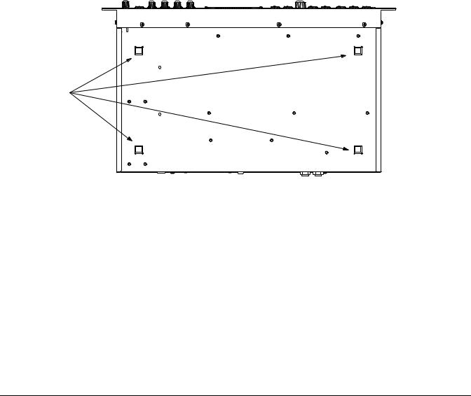
During operation, the PC2R must be either installed in a properly-ventilated MIDI rack, or resting on its four rubber feet on a sturdy, level surface. If not properly ventilated, the PC2R could overheat and malfunction.
Figure 2-1 shows the bottom panel of the PC2R and the recommended locations for the rubber feet. Peel the backing paper from each rubber foot and attach it as indicated.
Attach feet here
Figure 2-1 Attaching rubber feet
2-1
Startup
Basic Connections
Basic Connections
Figure 2-2 shows the PC2R’s rear panel, where you’ll find the power, audio, and MIDI connections.
Æ |
L |
R |
PC R2 |
In |
Thru |
Out |
Power In |
Digital Out |
MIDI |
|
|||||
Designed in USA Made in R.O.K. |
Audio Outs |
|
|
14.0V~0.25A |
|||
Serial No. |
|
|
|
|
|
|
Thru / Out |
Model: PC2R |
|
|
|
|
|
|
|
Manufacturer: Young Chang Co., Ltd. |
|
|
|
|
|
|
9.0V 2.0A |
THIS DEVICE COMPLIES WITH PART 15 OF THE FCC RULES. OPERATION IS SUBJECT TO THE FOLLOWING TWO CONDITIONS:
(1)THIS DEVICE MAY NOT CAUSE HARMFUL INTERFERENCE
(2)THIS DEVICE MUST ACCEPT ANY INTERFERENCE RECEIVED, INCLUDING INTERFERENCE THAT MAY CAUSE UNDESIRED OPERATION.
Figure 2-2 The PC2R’s rear panel
Power
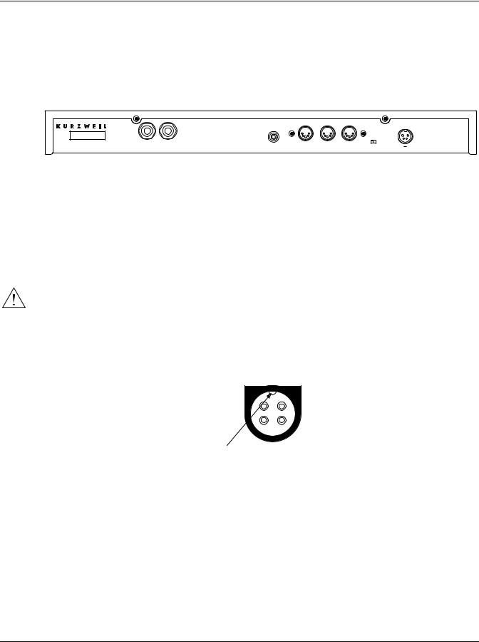
The PC2R has an external transformer/power supply with a standard electrical plug on one end, and a keyed four-pin plug that connects with the PC2R (“keyed” means that there’s only one way to connect it). This is a specialized power supply, and is not interchangeable with other power supplies.
Caution: Use only the power supply that comes with your PC2R, or a replacement purchased from an authorized Kurzweil dealer. Using a different power supply can seriously damage your PC2R!
Connect the keyed plug to the AC In connector. Figure 2-3 shows the correct orientation of the plug.
Flat side up!
Key
Figure 2-3 Proper orientation of plug
Place the power supply somewhere where it will stay dry and out of the way. We recommend keeping it on the floor. Never cover the power supply with anything; it needs adequate ventilation to prevent overheating.
Connect the plug at the other end of the power-supply cable into a standard power outlet. If you plan to take your PC2R to a location that uses a different voltage level, you’ll need to get an additional power supply that’s compatible with the local voltage.
The PC2R’s Power Switch/Volume knob (in the top left corner of the front panel) will probably be in the off position when you plug the instrument in for the first time. If it happens to be on, we recommend that you turn it off before making any further connections.
2-2

Startup
Basic Connections
Audio
The PC2R features balanced left and right analog audio outputs with 1/4-inch jacks. For best results, use balanced cables to connect to balanced, line-level inputs on your mixer or sound system.
It’s important to use shielded, twisted-pair cables. The cables should each have 1/4-inch stereo (tip-ring-sleeve) plugs on one end to connect to the PC2R. The other end of each cable should have either 1/4-inch stereo plugs or XLR plugs. Cables of this type provide balanced operation, which greatly reduces many types of noise. Unbalanced cables or sound-system inputs won’t give you quite the same audio quality.
For best performance, set the PC2R’s Master Volume knob to its maximum when adjusting mixer or sound-system levels. Otherwise, if you adjust the PC2R’s level by increasing the level of your sound system, you’ll increase the noise level.
If you’re using a monaural sound system or running the PC2R’s audio into a single mixer channel, we recommend configuring the PC2R for mono output, in which case the PC2R sends the same one-channel signal to the left and right sides of both the analog and digital outputs. See page 4-31 for information about using mono audio output mode.
The PC2R has a headphone jack, which carries the same signal as the main outputs (that’s true whether you’re using stereo or mono output). The headphone jack accepts a standard 1/4-inch stereo plug, and is compatible with nearly all types of headphones. Plugging into the headphones jack does not mute the other audio outputs.
You can also use the headphone jack as an unbalanced stereo line-level output. Just connect a stereo cable from the headphone jack to a stereo input on your mixer or sound system. If you have only unbalanced inputs to your sound system, you’ll get better audio quality using the headphone jack.
Digital Output
With the PC2R, you can take advantage of the growing number of digital recorders and mixers on the market. Connect a 75-Ohm coaxial cable from the PC2R’s RCA Digital Out jack to the AES or S/PDIF input of the receiving device. You may need an RCA-to-XLR adapter to connect with the receiving device. If the receiving device receives only optical signals, you’ll need a converter as well.
You can use the analog and digital audio outputs at the same time. There are five parameters in the Global menu that control the digital output configuration. You may want to edit some of these parameters, depending on how you’re using the PC2R’s digital output. In many (perhaps most) cases, however, the default values provide the best performance. For more information, see the descriptions of the digital audio output parameters, beginning on page 5-41.
MIDI
The PC2R accepts most standard (and several specialized) MIDI messages at its MIDI In port. It also has an Out port and a switchable Thru/Out port, so it can transmit certain MIDI messages—like program changes and system-exclusive (SysEx) information—as well as passing the MIDI information it receives on to other MIDI gear.
The typical MIDI configuration for the PC2R is to connect its MIDI In port to the MIDI Out port of a MIDI control source—a keyboard, an alternative controller like a wind or percussion controller, or a sequencer. The PC2R can receive information independently on all 16 MIDI channels.
2-3

Startup
Powering Up
Use the MIDI Out port and/or the programmable Thru/Out port if your PC2R is part of a more complex MIDI system.
Even if your MIDI source can transmit on only one MIDI channel, you can make it more powerful with the PC2R, which can remap incoming MIDI information to four different MIDI channels, each playing a different sound.
MIDI Configurations
You’re likely to set up your PC2R in some variation of one of three basic configurations:
•As s MIDI slave only, for use as a sound module; connect the MIDI Out of your MIDI source to the PC2R’s MIDI In.
•With a dedicated or computer-based sequencer or digital recording unit, for recording and multi-timbral (multi-channel) playback; connect the MIDI Out of your MIDI source to the MIDI In of your sequencer, and connect the MIDI Out of the sequencer to the MIDI In of the PC2R. In this case you’ll probably want to use MIDI Receive mode instead of the performance modes (see page 3-3 for more information).
•As both a MIDI slave and MIDI master, enabling you to pass MIDI information through the PC2R and play additional mult-timbral sound sources; connect the MIDI Out of your MIDI source to the MIDI In of the PC2R, and connect the MIDI Out and/or MIDI Thru/Out to the MIDI In of one or more additional instruments.
MIDI Thru/Out
This jack has two functions: it can be a MIDI Out port, enabling you to send directly to two different slaves, or it can be a MIDI Thru port, in which case it passes along whatever MIDI information that the PC2R receives at its MIDI In port (but not the MIDI information that the PC2R itself generates). This makes it easy to include the PC2R in a chain of multiple MIDI devices, which is a common configuration when you’re using a computer for sequencing.
There’s a small switch labeled Thru/Out on the PC2R’s rear panel (as you face the rear panel, the switch is to the left of the MIDI In port). You should be able use a finger to flip the switch to the desired position. If that doesn’t work, use a small pointed object—a ball-point pen works nicely.
Powering Up
When you’ve made all your connections, you’re ready to turn on the on the PC2R. First, turn the Power/Volume knob all the way to the left, then push it until it clicks. All of the lights on the front panel flash, and the liquid-crystal display (LCD) shows a series of messages. The first time you power up the PC2R, the display looks like this:
Bank:0||Internal||1A 000|Stereo Grand|
Caution: Before playing, we recommend that you turn the Volume knob all the way down (to the left), and gradually raise the volume while playing from your MIDI source. This way you won’t cause any pain or damage if there’s too much gain in your sound system.
When you turn the power off, the PC2R remembers the performance mode you’re in (or the corresponding editor). The next time you turn it on, it comes up in that mode.
2-4

Startup
Powering Up
Display (LCD)
The PC2R’s 40-character liquid-crystal display tells you what’s going on, whether you’re playing or editing. Depending on your viewing angle (and possibly the temperature), you may need to adjust the contrast for better visibility. There’s a small black knob at the far right of the front panel, which adjusts the LCD contrast so you can read the display easily in different lighting conditions.
LEDs
Most of the buttons on the PC2R’s front panel contain light-emitting diodes that indicate the status of the features that the buttons control. They should all flash as the PC2R starts up.
Software Upgrades
The PC2R contains a type of reloadable computer memory called Flash ROM, which makes software upgrades fast and easy. You can learn about new features from your Kurzweil dealer, or from our website (www.kurzweilmusicsystems.com). See Boot Block on page A-4 for software-installation instructions.
Playing the Demo Sequences
The PC2R features two demonstration sequences that show what you can do with a PC2R and a MIDI sequencer. The demos were recorded using PC2R sounds and effects exclusively.
1. Press the MIDI Receive and Global buttons together (notice the word Demo on the front panel under these two buttons). The display shows Select|a|demo... and (Cancel|to|exit). The LEDs in the Main and Layer buttons flash. If you decide not to play a demo, press Cancel to return to the previous mode.
2.Press Main to play the first demo, or press Layer to play the second. During playback, you can stop the demo by pressing Cancel.
Troubleshooting
No Text in Display
If no messages are displayed when you turn on the power on your PC2R and no LEDs flash, check the power adapter connections at the AC outlet and the PC2R Adapter In jack.
Low Battery
When you turn your PC2R off, a lithium battery protects the memory that the PC2R uses to store user-defined programs and setups, and other editing changes that you’ve saved. Every time you turn on your PC2R, it automatically checks the battery voltage. If it’s getting low, you’ll see a message like this before the PC2R finishes starting up:
|Battery|voltage|is
||low|(2.0|volts)
When you see this message, you should replace your battery immediately, to avoid losing your data. See page A-1 for instructions.
2-5

Startup
Powering Up
No Sound
If no sound comes from the audio or headphones outputs of your PC2R when you play your MIDI control source, check the following:
•The Volume knob might be set too low.
•Your MIDI connection may not be functioning: check that you have a MIDI cable connected from the MIDI Out port of your MIDI source to the MIDI In port of the PC2R. The LED in the MIDI Receive button blinks when the PC2R receives MIDI information.
•Your MIDI source may not be sending MIDI information.
•The channel on which you’re sending MIDI may be inactive in the PC2R: Press the MIDI Receive button; use a cursor button or the Alpha Wheel to select the channel that
your MIDI source is using; use a cursor button to select the Channel On/Off parameter; turn the Alpha Wheel to the right to change the value to On.
•There may be no current program or setup selected (the display shows Not|Found).
•If your MIDI source has a continuous pedal, check the connection, and check the position of the pedal.
•You might be in MIDI Setups mode with all zones muted (inactive): press any or all of the four buttons labeled Zone 1–Zone 4, and the lights in the buttons will turn green.
You could also try the “Panic” feature, which sends an All Notes Off and All Controllers Off message to the PC2R. Press the KB3 and MIDI Setups buttons at the same time.
2-6

Chapter 3
Playing Your PC2R
Changing Sounds
If your MIDI connections and channel assignments are OK, you should be able to change programs from your MIDI source—which is probably how most people do it. If you want to change programs from the PC2R however, you can. Just turn the Alpha Wheel in either direction to scroll through the list of available sounds.
There’s more about selecting programs and setups beginning on page 3-13.
Demonstration Sequences
There are two demo sequences stored in ROM. These demos were recorded using PC2R sounds and effects exclusively. See page 2-5 to learn how to play the demo sequences.
Also In This Chapter
Chapter 3 shows you how to get the most out of your PC2R in performance. The overview introduces a few important features and concepts, while the remaining sections provide more detail.
• |
Overview . . . . . . . . . . . . . . . . . . . . . . . . . . . . . . . . . . . . . . . . . . . |
. 3-2 |
• |
The Front Panel. . . . . . . . . . . . . . . . . . . . . . . . . . . . . . . . . . . . . . |
. 3-4 |
• Selecting Programs and Setups . . . . . . . . . . . . . . . . . . . . . . . . |
3-13 |
|
• |
EQ . . . . . . . . . . . . . . . . . . . . . . . . . . . . . . . . . . . . . . . . . . . . . . . . . |
3-14 |
• Using the Controllers on Your MIDI Source. . . . . . . . . . . . . . |
3-14 |
|
• |
Effects . . . . . . . . . . . . . . . . . . . . . . . . . . . . . . . . . . . . . . . . . . . . . . |
3-15 |
• |
Layering and Splitting . . . . . . . . . . . . . . . . . . . . . . . . . . . . . . . . |
3-18 |
• |
Muting and Soloing . . . . . . . . . . . . . . . . . . . . . . . . . . . . . . . . . . |
3-21 |
• Saving the Internal Setup . . . . . . . . . . . . . . . . . . . . . . . . . . . . . |
3-23 |
|
3-1

Playing Your PC2R
Overview
Overview
We’ll start by explaining how the PC2R is organized. In this overview we’ll discuss modes, programs and setups (and how they’re organized), objects, banks, and something called the Internal Setup. (described on page 4-14) We’ll also briefly mention EQ (equalization) and effects.
Modes
The PC2R has six modes. Each mode provides a different set of functions. You’ll choose modes depending on what you want to do with the PC2R. There are two kinds of modes: performance modes for playing sounds, and edit modes for programming them.
The three main performance modes are Internal Voices mode, KB3 mode, and MIDI Setups mode. You’ll use one of these modes whenever you’re playing your PC2R. Each mode organizes sounds into programs or setups, which we’ll describe below. Select a performance mode by pressing the corresponding button in the Modes region at the right side of the front panel.
Each of the performance modes has its own editor, where you can make changes to individual programs and setups.
There are also three special modes for programming effects, making channel-by-channel control assignments, and configuring the whole PC2R.
Performance Modes
Internal Voices (Programs)
Internal Voices mode lets you play one internal voice (program) at a time. A program consists of one or more sounds (like piano or strings), and the settings (parameters) that affect those sounds—for example, the highest and lowest notes for a particular sound. The PC2R starts in Internal Voices mode the first time you turn it on (after that, it starts in the performance mode you were in when you turned it off). See Program Structure on page 4-12 for more information about what’s in a program.
KB3 Mode (KB3 Programs)
In KB3 mode, the PC2R uses a different synthesizer technique (tone wheel emulation) to reproduce the sound of classic tone-wheel organs (like the Hammond B-3). In most other respects, KB3 mode is like Internal Voices mode. See KB3 Program Structure on page 4-15 for details.
MIDI Setups Mode (Setups)
MIDI Setups mode is what makes the PC2R such a flexible MIDI rack unit. In this mode you play setups instead of programs. Each setup can play up to four different programs, each on its own MIDI channel. See Setup Structure on page 4-16 for more information.
3-2
Playing Your PC2R
Overview
Special Modes
While you’re in Internal Voices mode, press Main to go to a special setup editor that controls the internal setup (see Editing the Internal Setup on page 4-32 for more information). The internal setup defines controller assignments and other characteristics for all the programs in Internal Voices mode. Pressing Main also enables you to create quick layers and splits, as described on page 3-18.
Effects Edit Mode
Press the FX button to get to Effects edit mode, where you can select and edit the effects associated with each program and setup. Effects edit mode is also accessible through the Program, KB3, and Setup Editors, but it’s often more convenient to go directly to Effects edit mode: just press FX, and you’re immediately looking at the first menu of effects parameters for the current program or setup.
There’s an exception that occurs when the value of the FX Chg Mode parameter—in the Global menu—has a value of Panel. In this case, you can still get directly to Effects edit mode by pressing the FX button, but Effects edit mode controls the effects for the entire PC2R, not just the current program or setup.
MIDI Receive Mode
Use MIDI Receive mode to configure each MIDI channel independently (this is the mode to use when you’re driving your PC2R from a multi-channel sequencer). You might think of this mode as a special performance mode for configuring individual MIDI channels—program assignment, volume and pan settings, effects routing, and the wet/dry mix of the effects.
Global Mode
Use Global mode to make changes that affect the entire PC2R—for example, tuning and transposition, MIDI clock source, program-change protocol, and more.
Objects
Throughout this manual, we’ll occasionally mention objects, which may sound a bit technical, so we’ll explain. Object is just a convenient name we use to refer to any chunk of information that the PC2R stores or processes. Programs and setups are objects, for example. So are effects. Many PC2R objects are invisible to you, but you’ll be working regularly with the highest-level objects: programs, setups, and effects. When you’re editing programs, there’s a good chance you’ll work with other important objects: keymaps. You might also use System Exclusive (SysEx) messages to store programs, setups or effects to an external device—or use a single SysEx message to store all the objects you’ve modified while editing.
EQ
Whichever mode you’re in, the PC2R can apply three-band equalization (EQ) to the programs you’re playing. Press the Global button to view the current EQ setting. See page 3-14 for more about changing the EQ settings.
3-3

Playing Your PC2R
The Front Panel
Effects
There are over 150 preset effects, including reverbs, delays, choruses, flangers, phasers, tremolo, panners, envelope filters, distortions, rotary speakers, compressors, enhancers, waveform shapers, and multi-effect combinations. There are also 30 preset reverbs. See page 3-15 for more information about effects.
The Front Panel
The buttons and knobs on the PC2R’s front panel control it during performances and when you’re editing.
PUSHPWR |
Performance |
Zone 1 |
Zone 2 |
|
Zone 3 |
Zone 4 |
PC2R |
Edit |
|
|
Modes |
|
|
|
VOL |
Solo |
Main |
Layer |
|
Split |
Split Layer |
Edit / Store Group / Menu |
Compare |
Copy |
Internal Voices |
KB3 |
MIDI Setups |
||
|
Rotary Fast / Slow |
Perc On / Off |
Volume |
|
Decay |
|
Pitch |
|
|
|
|
|
Panic |
|
|
Shift |
A |
B |
C |
|
D |
|
|
|
Cancel |
Enter |
FX |
MIDI Receive |
Global |
|
|
16' |
5 1/3' |
|
|
8' |
4' |
|
|
|
|
|
|
|
|
|
2 2/3' |
2' |
|
|
1 3/5' |
1 1/3' |
|
|
|
|
|
|
|
|
Drawbar Toggle |
1' |
Pre-Amp |
|
Chorus / Vib |
Chorus / Vib |
|
|
No |
Yes |
|
Demo |
||
|
|
|
|
|
|
On / Off |
Depth |
|
|
|
|
|
|
|
|
|
Performance region |
|
|
|
|
EdEdit regregionon |
|
|
Modes region |
||||
Figure 3-1 The PC2R’s front panel
The two-line, 40-character display (LCD) lets you know what’s going on, whether you’re performing or editing. There’s more about the display beginning on page 3-5.
In addition to the display, there are three main regions on the PC2R’s front panel. These regions are labeled in orange at the top of the front panel:
Performance |
As the label suggests, you’ll use the buttons and knobs in this region |
|
primarily when you’re in one of the performance modes. They affect various |
|
functions, depending on the performance mode. This region also includes the |
|
Power/Volume knob and the Headphones jack. |
Edit |
Use the buttons in this region (along with the Alpha Wheel) to select and edit |
|
parameters when you’re programming your PC2R. |
Modes |
There are two rows of buttons in this region. The buttons in the top row select |
|
the performance mode: Internal Voices, KB3, or MIDI Setups. |
|
The buttons in the bottom row select special modes for configuring your |
|
PC2R: the FX button selects parameters for selecting and routing effects; the |
|
MIDI Receive button selects parameters for determining how the PC2R |
|
responds to certain incoming MIDI messages; the Global button enters a |
|
menu of general parameters that affect the entire PC2R things like overall EQ |
|
and velocity sensitivity, among others). |
|
The Modes region also contains the adjustment knob for the display contrast; |
|
adjust the setting of this knob if you’re having trouble reading the display. |
For a more thorough discussion of the buttons and knobs in each region, see page 3-7.
3-4

Playing Your PC2R
The Front Panel
Color-Coded Labeling
Most of the buttons to the right of the display are labeled in a single color: white. These buttons have similar or related functions in most performance and editing modes.
Most of the buttons and knobs in the Performance region, however, are labeled with more than one color, or with more than one function. These multi-purpose buttons and knobs do different things depending on which mode you’re in. The color of the labeling in the Performance region corresponds to the color of the labeling of the mode-selection buttons: white corresponds to Internal Voices mode, orange corresponds to KB3 mode, and blue corresponds to MIDI Setups mode.
For example, there’s a button labeled Solo in white, and Rotary fast/Slow in orange. In Internal Voices mode, this button (Solo) switches to AutoSplit mode and solos the current zone.When you’re in KB3 mode, this button switches between fast and slow rotary effects for the current KB3 program. Any button with labeling in more than one color has different functions in different performance modes.
The Display (LCD)
The display looks quite different in each mode, so we’ll show you examples of each.
Internal Voices Mode
When you turn on your PC2R, the display should look like this:
Bank ID |
|
Bank name |
Bank index (category and program) |
||
|
|
|
|
|
|
|
|
|
|
|
|
Bank:0||Internal||1A 000|Stereo Grand|
Program ID and name
This is Internal Voices mode, where the PC2R always starts when you turn it on (to get to Internal Voices mode from another mode, press the Internal Voices button). The top line gives you information about the bank, while the bottom line shows the ID and name of the current program.
KB3 Mode
Press the KB3 Mode button to enter KB3 mode; the display changes to something like this:
Bank ID Program ID |
Program name |
||||
|
|
|
|
|
|
|
|
|
|
|
|
4:000|All Out|||||| P:888888885|CV:Chor1
Drawbar |
Drawbar values |
Chorus/Vibrato setting |
type |
(one digit for |
|
|
each harmonic |
|
|
wavelength) |
|
3-5

Playing Your PC2R
The Front Panel
You’ll find KB3-mode programs in banks with IDs 4 and 5. Unlike Internal-Voices programs and setups, they don’t display a bank index.
KB3 programs use tone-wheel synthesis to produce sound. When you select a KB3 program (or a setup that contains one), the tone wheels start up and run constantly while the program is in use. This requires quite a bit of processing, and consequently has an effect on the polyphony available for other programs. KB3 programs use 44 of the PC2R’s 64 available voices, so when you use a KB3 program in a setup, you have 20 voices of polyphony available for the remaining programs in the setup.
Because of the special processing requirements of KB3 programs, you can play only one KB3 program at a time (this is true in all performance modes). There’s a parameter in the Global menu called KB3 MIDI Chan, which specifies which MIDI channel is available for playing KB3 programs. You can’t play KB3 programs on any other channel. This is important to note if you’re playing the PC2R from an external sequencer. In this case, make sure that the sequencer selects KB3 programs only on the KB3 channel; otherwise, the KB3 program won’t play.
KB3 programs have nine adjustable drawbar settings, with harmonic wavelengths ranging from 1 to 16 feet. You can change the drawbar settings using the drawbar controls: Knobs A–D and the Drawbar Toggle (Shift) button. Here’s how it works:
When the LED in the Drawbar Toggle button is green, Knobs A–D represent drawbars 1–4 (the four longest—or lowest-pitched—harmonic wavelengths). Press the Drawbar Toggle button, and its LED turns amber. The knobs then represent drawbars 5–8 (shorter, higher-pitched wavelengths). Press Drawbar Toggle again, and its LED turns red. Now Knob A controls Drawbar 9 (the shortest), and Knobs B–D control other KB3 features.
There are nine digits in the bottom line of the display that show the current drawbar values. From left to right, they correspond to drawbars 1–9. Moving one of the drawbars changes the corresponding drawbar values, and changes the nature of the organ sound.
Try it out. Make sure you’re in KB3 mode, then move one of the knobs. You’ll see one of the values on the bottom line change. By default, moving a knob all the way to the left is equivalent to pulling out the drawbar on a real organ. The corresponding value is 8. Conversely, turning the knob all the way to the right is equivalent to pushing the drawbar in, with a corresponding value of 0. If you change the value of the MIDI In parameter (in the Global menu) to Normal or Merge, you’ll reverse the effect of the drawbar control knobs.
When the Drawbar Toggle LED is red, the Pre-Amp knob (Knob B) is at minimum when all the way to the left. The Chorus/Vib On/Off knob (Knob C) turns chorus or vibrato off when you turn it to the left past the halfway point, and on when you turn it to the right past the halfway point. The Chorus/Vib Depth knob (Knob D) scrolls through the chorus and vibrato settings as you turn the knob from left to right.
To the left of the drawbar values, there’s a letter (either P or L) that indicates whether the program has preset or “live” drawbar values. A program with preset drawbars always starts with the same factory-set drawbar values when you select the program. Moving the drawbar controls changes their values temporarily, but the next time you select that program, the drawbars will once again be at their preset startup values. (You can edit the startup values for programs with preset drawbars; see Changing Preset Drawbar Values on page 4-32.)
A program with live drawbars starts with drawbar values that reflect the positions of the drawbar controls. Moving the drawbar controls changes their values further. Most of the KB3 programs have preset drawbars, although you can also edit them to have live drawbars.
3-6

Playing Your PC2R
The Front Panel
MIDI Setups Mode
Press the MIDI Setups button to enter MIDI Setups mode, and the display looks like this:
Setup ID |
|
Setup name |
|
|
|
|
|
|
S001|Dance C7|
A01|1:Beat Box|
Bank |
Current |
Program assigned to |
index |
zone |
current zone |
The setup ID usually begins with S to indicate that you’re playing a setup—although in Setups that have the AutoSplit feature turned on, the S is replaced by a caret (^). Notice that the bank index is a letter followed by a numeral, which is the opposite of the way the bank index looks in Internal Voices mode. This is convenient if you’re controlling the PC2R from a PC2, because you can use the Group button on the PC2 to select a group of setups, then use the Sound Select buttons to select one of the 16 setups in that group.
The Performance Region
Depending on how you use your PC2R, you may control it more from your MIDI source than from the PC2R’s front panel. Still, we’ve tried to organize the front panel so that everything you might need in a performance situation is easy to reach, and separate from the programming functions.
There are two rows of buttons and knobs in the Performance region. Their functions vary depending on your performance mode.
Solo
In either Internal Voices mode or MIDI Setups mode, pressing this button turns on the solo feature (if you’re in Internal Voices mode, the PC2R switches to AutoSplit mode—a special performance configuration of MIDI Setups mode.). When the Solo feature is on, (that is, when its LED is lit), pressing one of the Zone buttons solos that zone, so you hear that zone only. See page 3-21 for more about muting and soloing.
In KB3 mode, this button switches between fast and slow rotary effects (if any) for the current program.
Main
In Internal Voices mode, this button takes you to AutoSplit mode—a special performance and editing configuration of MIDI Setups mode. In this case, the Zone 2–Zone 4 buttons add splits or layers, as indicated (see page 3-18 for more information about layering and splitting).
In KB3 mode, this button turns the percussion effect on or off for the current program.
In MIDI Setups mode, this button selects Zone 1 for viewing or editing. Press it again to mute/unmute the zone.
3-7

Playing Your PC2R
The Front Panel
Layer
In Internal Voices mode, this button switches the PC2R into AutoSplit mode, and adds a layer.
In KB3 mode, this button switches between low and high volume for the percussion effect (if any) for the current program.
In MIDI Setups mode, this button selects Zone 2 for viewing or editing.
Split
In Internal Voices mode, this button switches the PC2R into AutoSplit mode, and adds a new sound below a preset split point.
In KB3 mode, this button switches between fast and slow decay for the percussion effect (if any) for the current program.
In MIDI Setups mode, this button selects Zone 3 for viewing or editing.
Split Layer
In Internal Voices mode, this button switches the PC2R into AutoSplit mode, and adds a layer to the sound below the split point.
In KB3 mode, this button switches between high and low pitch for the percussion effect (if any) for the current program.
In MIDI Setups mode, this button selects Zone 4 for viewing or editing.
In any performance mode, pressing Split and Split Layer together is an editing shortcut that displays the AutoSplit Key parameter. You can then use the Alpha Wheel to change the AutoSplit key (or hold down the Enter button and play a note on your MIDI source). Press Cancel to return to your performance mode.
Shift
The Shift button controls the functions of Knobs A–D (described below). Each time you press Shift, its LED changes color—from green to amber to red. Each of these states causes
Knobs A–D to have a different set of functions. The default functions of the knobs depend on your performance mode (they do different things in each mode). You can program them for different functions as well.
Knobs A–D
In Internal Voices mode and MIDI Setups mode, Knobs A–D control various program characteristics, as defined by a series of parameters in the Controllers menu in the Setup Editor. Remember that controller assignments in Internal Voices mode are defined by the internal setup, which you can edit in AutoSplit mode (which is a subset of the Setup Editor)—while in Internal Voices mode, press Main; hold Global and move a knob to select its Ctrl Num parameter; change its value; press Store; press the Internal Voices button at the Save prompt. See page 3-23.
3-8

Playing Your PC2R
The Front Panel
The following table shows the parameters that correspond to Knobs A–D, for each state of the Shift LED when you’re in Internal Voices mode or MIDI Setups mode. When the parameter name includes the word “Knob,” the corresponding knob functions as a continuous controller. When the parameter name includes the word “Switch,” the corresponding knob functions as a switch controller.
|
Knob A |
Knob B |
Knob C |
Knob D |
|
|
|
|
|
Green |
Green Knob A |
Green Knob B |
Green Knob C |
Green Knob D |
|
|
|
|
|
Amber |
Amber Swch A |
Amber Swch B |
Amber Swch C |
Amber Swch D |
|
|
|
|
|
Red |
Red Switch A |
Red Knob B |
Red Knob C |
Red Knob D |
|
|
|
|
|
In KB3 mode, Knobs A–D adjust drawbar lengths, pre-amp settings, and chorus/vibrato settings for KB3 programs. You’ll notice that these knobs each have three rows of labeling in orange. Each row of labeling corresponds to one of the states of the Drawbar Toggle LED. The default assignments for the knobs are as follows:
|
Knob A |
Knob B |
Knob C |
Knob D |
||||
|
|
|
|
|
|
|
|
|
Green |
Drawbar 1 |
(16') |
Drawbar 2 |
(5 1/3') |
Drawbar 3 |
(8') |
Drawbar 4 |
(4') |
|
|
|
|
|
|
|
|
|
Amber |
Drawbar 5 |
(2 2/3') |
Drawbar 6 |
(2') |
Drawbar 7 |
(1 3/5') |
Drawbar 8 |
(1 1/3') |
|
|
|
|
|
|
|||
Red |
Drawbar 9 |
(1') |
Pre-amp level |
Chorus/Vibrato On/Off |
Chorus/Vibrato Depth |
|||
|
|
|
|
|
|
|
|
|
If your MIDI source has programmable sliders or other physical controllers, you can program those controllers to work the way Knobs A–D work. See page B-12 for a list of the MIDI Controller messages that affect PC2R features.
The Edit Region
There are eight buttons, and a dial called the Alpha Wheel, in the Edit region. Most of the buttons you’ll need for programming (editing) your PC2R are in this region. (We’ll discuss editing thoroughly in Chapter 4.)
Four of the buttons in the Edit region have dual labels. For readability, when we refer to these buttons, we’ll describe them according to the situation, instead of using the full name. For example, to enter an edit mode, we’ll instruct you to press Edit (not Edit/Store).
Edit/Store
Press the Edit button to enter the edit mode corresponding to your current performance mode.This is where you make changes to the parameters that define programs, setups, and effects. See Chapter 4 for specifics about programming your PC2R.
Once you’re in an edit mode, this button becomes the Store button. Press Store to bring up a Save dialog, then either press Yes to save the current object, or use the cursor buttons to select another related function. See Naming and Storing on page 4-3 for more information.
Group/Menu
In all three performance modes, this button is the Group button, and selects categories of programs or setups. (See page 3-13 for more information about using the Group button to select programs and setups by category.)
3-9

Playing Your PC2R
The Front Panel
To select a program or setup this way, press the Group button to display a category of programs or setups. Use the Alpha Wheel or cursor buttons to scroll through the categories. Press Enter to select the first program or setup in that category.
If you’re in Internal Voices mode or KB3 mode, you can scroll all the way through the Internal Voices categories and into the KB3 categories (and vice versa). The PC2R automatically switches to the corresponding performance mode. Setups are separate, however; you can’t switch performance modes by scrolling through setup categories.
When you’re editing programs or setups, press Menu to select the first menu of programming parameters in the current edit mode. Use the cursor buttons to view the available menus, then press Enter to view the parameters in the current menu. When you’re viewing parameters, press Menu again to return to the list of menus.
Cursor Buttons
These are the Left and Right arrow buttons under the Edit/Store and Group/Menu buttons.We call them cursor buttons because they control the cursor, which is a bar that appears under one of the characters in the display. The position of the cursor indicates what’s selected for changing or editing.
The following table shows what happens in each performance mode when you press one of the cursor buttons.
Mode |
Function |
|
|
Internal Voices |
Selects bank ID parameter or program ID parameter |
|
|
KB3 |
Selects bank ID parameter, program ID parameter, or chorus/vibrato setting parameter |
|
|
MIDI Setups |
None |
|
|
You’ll also use the cursor buttons when editing, to select what you want to edit. See Basic Editing Concepts on page 4-1 for more about the cursor buttons.
Compare
When you’re editing, the Compare button lets you listen to the effect of a change, then to check the original. See page 4-8 for details.
Copy
When you’re editing setups, you can copy a zone and paste it into another zone, either in the same setup, or in a different setup.
Cancel/No
Use this button to exit from edit modes, and to answer “No” to prompts in the display (like
Save|Voice|1?).
Enter/Yes
Use this button to enter program or setup categories in performance modes, to get into menus while editing, and to answer “Yes” to prompts in the display.
3-10

Playing Your PC2R
The Front Panel
The Modes Region
The six buttons in the Modes region take you to various performance and editing modes.
Internal Voices
Press this button to get to Internal Voices mode from any performance or editing mode. Internal Voices is the mode to use for playing Internal-Voice programs.
KB3
Press this button to get to KB3 mode from any performance or editing mode. KB3 mode offers several programs that emulate the classic B-3 organ.
MIDI Setups
Press this button to get to MIDI Setups mode from any performance or editing mode. Use MIDI Setups mode when you want to play programs on up to four different MIDI channels.
FX
The FX button takes you to the FX Routing menu in the edit mode that corresponds to your current performance mode. For example, if you’re in MIDI Setups mode, pressing FX takes you to the Setup Editor (the Zone Parameters menu).
From the FX Routing menu, you can assign a different effect to the current program or setup, and you can edit the current effect. See page 4-28 for more information about editing effects.
MIDI Receive
This button takes you to MIDI Receive mode, where you can configure how the PC2R responds to incoming MIDI information. The first time you enter MIDI Receive mode after powering up, the display shows Channel 1, because the PC2R resets the MIDI Receive channel each time you shut down. Until you shut down again, the PC2R tracks which channel you’re viewing even after you’ve left MIDI Receive mode, so the next time you enter MIDI Receive mode, the display shows the channel you were most recently viewing.
Use the cursor buttons to select the parameters for each channel. You can scroll beyond the parameters for a given channel and move to the parameters for the next higher or lower channel. A faster way to jump to a different channel is to select the Channel parameter (that is, to move the cursor under the channel number), then use the Alpha Wheel to change channels. You can press either MIDI Receive or Cancel to jump immediately to the Channel parameter.
Another navigation short cut is to press both cursor buttons at the same time. When you do this, you jump to the corresponding parameter for the next higher channel (or back to Channel 1 if you’re looking at channel 16).
3-11

Playing Your PC2R
Program and Setup Organization
You can set the following parameters for each channel. See page 5-33 for more information about using MIDI Receive mode.
•Channel On/Off
•Program
•Volume
•Pan
•Effects routing
•Wet/Dry mix from output of FX-A to input of FX-B
•Wet/Dry mix to input of FX-A
•Wet/Dry mix to input of FX-B
Global
The Global button takes you to a list of parameters and functions affecting the entire PC2R There’s a description of each global parameter/function beginning on page 5-35.
Demo
Press MIDI Receive and Global together to enter a special demo mode. Then press Main or Layer (in the Performance region) to play a demo sequence. Press Cancel to stop playback, or to exit from demo mode.
Panic
Press KB3 and MIDI Setups together for the “Panic” function. This sends All Notes Off messages and All Controllers Off messages on all MIDI channels—both to the PC2R’s sound engine and to its MIDI Out port.
Program and Setup Organization
The PC2R’s programs and setups are arranged in banks; each bank can contain 128 programs or setups. The PC2R has a total of eleven banks, as shown in the following table:
Mode |
Bank |
Bank |
Bank |
Comment |
|
ID |
Name |
Contents |
|||
|
|
||||
|
|
|
|
|
|
|
0 |
Internal |
Programs 0–127 |
Factory programs |
|
|
|
|
|
|
|
|
1 |
User |
Empty |
Can store 128 user-defined programs numbered 0–127 |
|
Internal |
|
|
|
|
|
2 |
Exp1 |
Empty |
Reserved for internal programs contained in future expansion block |
||
Voices |
|||||
|
|
|
|
||
|
3 |
Exp2 |
Empty |
Reserved for internal programs contained in future expansion block |
|
|
|
|
|
|
|
|
6 |
Int2 |
Programs 0–127 |
Factory programs |
|
|
|
|
|
|
|
|
4 |
Internal |
KB3 programs |
Total of 16 factory KB3 programs, numbered in increments of 8 |
|
KB3 |
0–120 |
||||
|
|
|
|||
|
|
|
|
||
|
5 |
User |
Empty |
Can store 128 user-defined KB3 programs numbered 0–127 |
|
|
|
|
|
|
|
|
0 |
Internal |
Setups 0–32 |
Factory setups |
|
|
and 125–128 |
||||
|
|
|
|
||
MIDI |
|
|
|
|
|
1 |
User |
Empty |
Can store 128 user-defined setups numbered 129–256 |
||
Setups |
|
|
|
|
|
2 |
Exp1 |
Empty |
Reserved for factory setups contained in future expansion block |
||
|
|||||
|
|
|
|
|
|
|
3 |
Exp2 |
Empty |
Reserved for factory setups contained in future expansion block |
|
|
|
|
|
|
3-12
Loading...