


 Loading...
REPAIRMANUAL2002-2006
50 AC/LC
REPARATURANLEITUNG
MANUALE DI RIPARAZIONE
MANUEL DE REPARATION
MANUAL DE REPARACION
Art.NR.: 3.206.028-E
|
AC/LC 50 |
MANUALREPAIR |
|
|
2006-2002 |
|
|
|
|
|
|
KTM Group Partner
1 SERVICE-INFORMATIONS
2 GENERAL INFORMATION
3 REMOVING AND REFITTING ENGINE
4 DISASSEMBLING ENGINE
5 SERVICING INDIVIDUAL COMPONENTS
6 ASSEMBLING ENGINE
7 TROUBLE SHOOTING
8 TECHNICAL SPECIFICATIONS
9 PERIODIC MAINTENANCE SCHEDULE
10 WIRING DIAGRAM
11
12
13
14
15
16

IMPORTANT INFORMATION/UPDATING INSTRUCTIONS
To be able to continue using the existing loose-leaf repair instructions, simply print the following pages and insert them in the existing repair instructions:
1, 3, 7, 9, 13, 15, 17, 20, 21, 33, 46, 61, 63, 74, 76 - 81, 82, 84, 86, 87
|
Remove page (s) |
Replace by page (s) |
Insert page (s) |
after page |
|
|
|
|
|
|
2-1 |
2-1E |
|
|
|
|
|
|
|
|
2-2 |
2-2E |
|
|
|
|
|
|
|
|
|
|
2-5E to 2-6E |
2-4 |
|
|
|
|
|
|
4-2 |
4-2E |
|
|
|
|
|
|
|
|
5-7 |
5-7E |
|
|
|
|
|
|
|
|
8-1 |
8-1E |
|
|
|
|
|
|
|
|
8-2 |
8-2E |
|
|
|
|
|
|
|
|
8-12 |
8-12E |
|
|
|
|
|
|
|
-E |
8-14 |
8-18E |
|
|
|
|
|
|
|
3.206.028 |
|
|
8-14E to 8-17E |
8-13 |
|
|
|
||
|
|
|
|
|
|
9-1 to 9-2 |
9-1E to 9-2E |
|
|
|
|
|
|
|
Art.-Nr. |
9-4 |
9-4E |
|
|
|
|
|
|
|
|
|
9-6E to 9-7E |
9-5 |
|
|
|
|
|
|
KTM REPAIR MANUAL IN LOOSE-LEAF FORM
|
STORING THE REPAIR MANUAL IN THE BINDER |
|
|
– Put the index into the binder. |
|
|
– Put the front page of the repair manual (210x297 mm) into the transparent pocket provided for this purpose on the outside of |
|
|
|
the binder. |
|
– Put the spine label (170x45 mm) into the transparent pocket provided for this purpose on the spine of the binder. |
|
cooled |
– |
Put the summary list of contents (150x297 mm) into the transparent pocket provided for this purpose on the inside of the |
– |
Then insert the individual chapters of the manual between the sheets of the index according to the page number printed in |
|
|
|
binder or insert this page on the beginning of the manual. |
air/liquid |
|
the right bottom corner of each page. |
|
Example: page no. 3-5, 3 = chapter 3, 5 = page 5. All pages with a page number that begins with the digit 3, for example, |
|
|
|
|
|
|
must be put under the index heading "Chapter 3". |
50 |
– |
Index sheets that have not been marked with a certain chapter are for your personal convenience. The respective headings |
|
can be entered in the list of contents. |
|
MINI |
|
|
|
|
|
KTM |
|
|
Repair manual |
|
|

EX P L A N A T I O N - UP D A T E
This repair manual contains the following supplements:
Art.-Nr. 3.206.028 -E
3.210.24-E Repair Manual 50 AC/LC |
5/2001 |
Basic version Model year 2002 |
|
3.210.64-E Updating of Rep.Manual 3.210.24-E |
5/2002 |
Model year 2003 |
|
(Engine number with first digit „3“) |
|
3.206.010-E Updating of Rep.Manual 3.210.24-E |
5/2003 |
Model year 2004 |
|
(Engine number with first digit „4“) |
|
Repair manual KTM MINI 50 air/liquid cooled
3.206.018-E Updating of Rep.Manual 3.210.24-E |
4/2004 |
Model year 2005
(Engine number with first digit „5“)
3.206.028-E Updating of Rep.Manual 3.210.24-E |
7/2005 |
Model year 2006
(Engine number with first digit „6“)
Modification / Updating:
Technical Details Model 2006, Changing brake fluid, Special Tools,
Technical Specifications, tightening torques, Periodic Maintenance Schedule
Edition: 7/2005
INTRODUCTION
This repair manual offers extensiv repair-instructions and is an up-to-date version that describes the latest models of the series. However, the right to modifications in the interest of technical improvement is reserved without updating the current issue of this manual.
A description of general working modes common in work shops has not been included. Safety rules common in the work shop have also not been listed. We take it for granted that the repairs are made by qualified profesionally trained mechanics.
Read through the repair manual before beginning with the repair work.
|
WARNING |
|
STRICT COMPLIANCE WITH THESE INSTRUCTIONS IS
ESSENTIAL TO AVOID DANGER TO LIFE AND LIMB.
! |
CAUTION |
! |
NON-COMPLIANCE WITH THESE INSTRUCTIONS CAN LEAD
TO DAMAGE OF MOTORCYCLE COMPONENTS OR RENDER
MOTORCYCLES UNFIT FOR TRAFFIC !
„NOTE“ POINTS OUT USEFUL TIPS.
Use only ORIGINAL KTM SPARE PARTS when replacing parts.
The KTM high performance engine is only able to meet user expectations if the maintenance work is performed regularly and professionally.
In accordance with the international quality management ISO 9001 standard, KTM uses quality assurance processes that lead to the highest possible product quality.
© 2004 by KTM-SPORTMOTORCYCLE AG, Mattighofen AUSTRIA; All rights reserved; Reprint, also in extracts, with written allowance of KTM-SPORTMOTORCYCLE AG, Mattighofen only.

Art.-Nr. 3.206.028 -E
Repair manual KTM MINI 50 air/liquid cooled
REPLY FAX FOR REPAIR MANUALS
We have made every effort to make our repair manuals as accurate as possible but it is always possible for a mistake or two to creep in.
To keep improving the quality of our repair manuals, we request mechanics and shop foremen to assist us as follows:
If you find any errors or inaccuracies in one of our repair manual - whether these are technical errors, incorrect or unclear repair procedures, tool problems, missing technical data or torques, inaccurate or incorrect translations or wording, etc. - please enter the error(s) in the table below and fax the completed form to us at 0043/7742/6000/5349.
NOTE to table:
–Enter the complete item no. for the repair manual in column 1 (e.g.: 3.210.028-E).
You will find the number on the cover page or in the left margin on each right page of the manual.
–Enter the corresponding page number in the repair manual (e.g.: 5-7c) in column 2.
–Enter the current text (inaccurate or incomplete) in column 3 by quoting or describing the respective
passage of the text. If your text deviates from the text contained in the repair manual, please write your text in German or English if possible.
–Enter the correct text in column 4.
Your corrections will be reviewed and incorporated in the next issue of our repair manual.
Item no. of repair manual |
Page |
Current text |
Correct text |
|
|
|
|
|
|
|
|
|
|
|
|
|
|
|
|
|
|
|
|
|
|
|
|
|
|
|
|
|
|
|
|
|
|
|
|
|
|
|
|
|
|
|
|
Additional suggestions, requests or comments on our Repair Manuals (in German or English):
Name mechanic/shop foreman: |
Company/work shop: |
|
|
|
|
|
2-1E |
|
|
|
|
|
|
|
|
|
|
|
|
GENERAL INFORMATION |
2 |
|
|||
|
|
|
|
|
|
|
|
|
|
|
|
|
|
|
|
|
|
|
INDEX |
|
|
|
|
|
|
|
|
|
|
|
|
|
|
|
|
|
|
|
|
|
|
OPERATING RANGES OF THE CARBURETOR . . . . . . . . . . . . . . . . . . . . . . . . . . . |
.2-2 |
|
|
||
|
|
CLEANING AND STORAGE . . . . . . . . . . . . . . . . . . . . . . . . . . . . . . . . . . . . . . . . |
.2-3 |
|
|
||
|
|
BLEEDING OILPUMP FOR SEPARATE LUBRICATION . . . . . . . . . . . . . . . . . . . . . . . |
2-4 |
|
|
||
|
|
CHANGING FRONT BRAKE FLUID . . . . . . . . . . . . . . . . . . . . . . . . . . . . . . . . . . . . |
2-5 |
|
|
||
|
|
CHANGING REAR BRAKE FLUID . . . . . . . . . . . . . . . . . . . . . . . . . . . . . . . . . . . . . |
2-6 |
|
|
||
|
|
CHECKING BRAKE PADS AND BRAKE DISCS . . . . . . . . . . . . . . . . . . . . . . . . . . . . |
2-6 |
|
|
||
|
|
|
|
|
|
|
|
Art.-Nr. 3.206.028-E
Repair manual KTM MINI 50 air/liquid cooled
Art.-Nr. 3.206.028 -E
Repair manual KTM MINI 50 air/liquid cooled
2-2E
Carburetor adjustment
Basic information about original carburetor setting
The original carburetor setting was adapted for an altitude of approx. 500 meters (1600 ft.) above sea level, and the ambient temperature of approx. 20° C (68° F), mainly for off-road use and central European premium-grade fuel (ROZ 95).
Mixing ratio 2-stroke motor oil:super fuel up to model 2005 1:40, as of model 2006 1:60.
Basic information about change of the carburetor setting
Always start out from the original carburetor setting. Essential requirements are a clean air filter system, air-tight exhaust system and an intact carburetor. Experience has shown that adjusting the main jet, the idling jet and the jet needle is sufficient and that changes of other parts of the carburetor will not greatly affect engine performance.
RULE OF THUMB: |
high altitude or high temperatures |
|
choose leaner carburetor adjustment |
|
low altitude or low temperatures |
|
choose richer carburetor adjustment |
|
|
|
|
! |
WARNING |
! |
|
– ONLY USE PREMIUM-GRADE GASOLINE ROZ 95 MIXED WITH HIGH-GRADE TWO-STROKE ENGINE OIL. OTHER TYPES OF GASOLINE CAN CAUSE ENGINE FAILURE, AND USE OF SAME WILL VOID YOUR WARRANTY.
–ONLY USE HIGH-GRADE 2-STROKE ENGINE OIL OF KNOWN BRANDS (I. E. Motorex Cross Power 2T).
–LESS OIL OR LOW-GRADE OIL CAN CAUSE EXCESSIVE WEAR OF THE PISTON. USING TOO MUCH OIL, THE ENGINE CAN START SMOKING AND FOUL THE
SPARK PLUG.
– IN THE CASE OF A LEANER ADJUSTMENT OF THE CARBURETOR PROCEED CAUTIOUSLY. ALWAYS REDUCE THE JET SIZE IN STEPS OF ONE NUMBER TO AVOID OVERHEATING AND PISTON SEIZURE.
NOTE: If despite a changed adjustment the engine does not run properly, look for mechanical faults and check the ignition system.
Basic information on carburetor wear
As a result of engine vibrations, throttle valve, jet needle, and needle jet are subjected to increased wear. This wear may cause carburetor malfunction (e.g., rich mixture). Therefore, these parts should be replaced after 1000 hours of using.
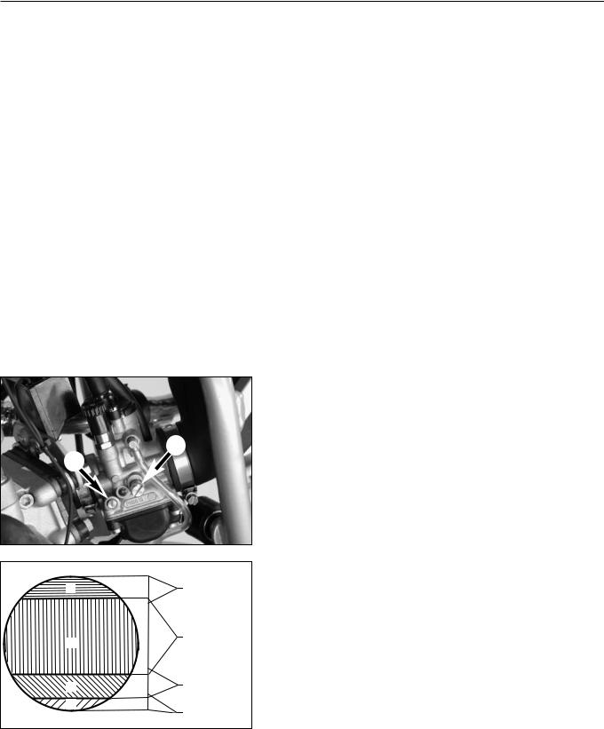
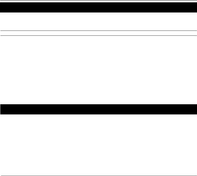
1 2
2
D |
main jet |
|
|
||
|
jet needle |
|
C |
jet needle |
|
|
||
B |
idling jet |
|
throttle valve |
||
A |
||
idling jet |
||
|
Idling range – A
Operation with closed throttle valve. This range is influenced by the position of the mixture adjusting screw 1 and the idle adjusting screw 2. Only make adjustments when the engine is hot.
To this end, slightly decrease the idling speed of the engine by means of the idle adjusting screw. Turning it clockwise produces a higher idling speed and turning the screw counterclockwise produces a lower idling speed. Create a round and stable engine speed using the mixture adjusting screw (basic position of the mixture adjusting screw = open 3.5/3 turns). Then adjust to the normal idling speed by means of the idle adjusting screw.
Opening up – B
Engine behavior when the throttle opens. The idle jet and the shape of the throttle valve influences this range. If, despite good idling-speed and part-throttle setting, the engine sputters and smokes when the throttle is fully opened and develops its full power not smoothly but suddenly at high engine speeds, the mixture to the carburetor will be too rich, the fuel level too high or the float needle is leaking.
Part-throttle range – C
Operation with partly open throttle valve. This range is only influenced by the jet needle (shape and position). The optimum part-throttle setting is controlled by the idling setting in the lower range and by the main jet in the upper range. If the engine runs on a four-stroke cycle or with reduced power when it is accelerated with the throttle partly open, the jet needle must be lowered by one notch. If then the engine pings, especially when accelerating under full power at maximum engine revs, the jet needle should be raised.
If these faults should occur at the lower end of the part throttle range at a four-stroke running, make the idling range leaner; if the engine pings, adjust the idling range richer.
Full throttle range – D
Betrieb bei offenem Gasschieber (Vollgas). Dieser Bereich wird durch Operation with the throttle fully open (flat out). This range is influenced by the main jet and the jet needle. If the porcelain of the new spark plug is found to have a very bright or white coating or if the engine rings, after a short distance of riding flat out, a larger main jet is required. If the porcelain is dark brown or black with soot the main jet must be replaced by a smaller one.
2-3E
CLEANING
Clean your motorcycle regularly in order to keep its painted finish looking shiny and new.
The best manner would be to use warm water that has been mixed with a commercially available washing detergent and a sponge. The hard dirt can be removed before with the help of a soft water jet.
! CAUTION !
NEVER CLEAN YOUR MOTORCYCLE WITH A HIGH-PRESSURED CLEANER OR A HIGH-PRESSURED WATER JET. OTHERWISE THE WATER MIGHT RUN INTO THE ELECTRICAL COMPONENTS, CONNECTORS, SHEATHED CABLES, BEARINGS, CARBURETOR ETC. AND CAUSE MAILFUNCTIONS, I.E., LEAD TO THE PREMATURE DESTRUCTION OF THESE PARTS.
–You should use commercially available detergents to clean the motorcycle. Heavily soiled parts should also be cleaned with the help of a paint brush.
–Befor cleaning with water, plug the exhaust pipe to prevent water ingress.
–After the motorcycle has been rinsed with a soft water jet, it should be dried by air pressure and a cloth. Then take a short drive until the engine has reached its operating temperature, and also operate the brakes. The heat also causes the water at the inaccessible parts of the engine and the brakes to evaporate.
–Slide back the protective covers on the handlebar-mounted instruments so that any water that may have seeped into this part of the motorcycle is allowed to evaporate.
–After the motorcycle has cooled down, oil and grease all the gliding bearing parts. Also treat the chain with a chain spray.
–To prevent failures in the electric system, you should treat the short circuit button with a contact spray.
STORAGE
If you want to put your motorcycle away for longer periods of time, please observe the following instructions:
–Clean motorcycle thoroughly (see chapter: CLEANING)
–Change engine oil (old engine oil contains aggresive contaminations).
–Check antifreeze and amount of cooling liquid.
–Let the engine warm up again, close fuel tap and wait until the engine dies off by itself. In this way, the carburetor jets are prevented from becoming resin-clogged by the old fuel.
–Remove spark plug and fill in approx. 5 ccm of engine oil into the cylinder through the opening. Actuate kick-starter 10 times in order to distribute the oil onto the cylinder walls and mount the spark plug.
–Let fuel flow out of tank into an appropriate basin.
–Correct tire pressure.
–Lubricate bearing points of the control levers, foot rests, etc. as well as the chain.
–The storage place should be dry and not be subject to overly great temperature fluctuations.
–Cover the motorcycle with an air permeable tarpaulin or blanket. Do not use non-air-permeable materials, as possible humidity might not be able to escape and thereby cause corrosion.
! |
CAUTION |
! |
IT WOULD BE VERY BAD TO LET THE ENGINE RUN FOR A SHORT TIME DURING THE STORAGE PERIOD. THE ENGINE WOULD NOT GET WARMED UP ENOUGH AND THE THUS DEVELOPED STEAM WOULD CONDENSE DURING THE COMBUSTION PROCESS AND CAUSE THE EXHAUST TO RUST.
USE AFTER PERIOD OF STORAGE
–Fill up tank with fresh fuel.
–Check motorcycle as before each start (see driving instructions)
–Take a short, careful test ride first.

Art.-Nr. 3.206.028 -E
Repair manual KTM MINI 50 air/liquid cooled
2-4E
2
 1
1
2
 3 A
3 A
 4
4
 4
4
Bleeding oilpump for separate lubrication up to model 2003
Clamp oil lines 1 and 2 as shown.
Add 2 stroke engine oil (for example Motorex Cross Power 2T) with a syringe until the bubble-free oil starts to leak out of the line 2.
After bleeding the oil pump, mount both oil lines and fill the oil tank with 2 stroke engine oil (for example Motorex Cross Power 2T).
! |
CAUTION |
! |
HOSE 2 LEADING FROM THE OIL PUMP TO THE CARBURETOR MUST BE INSTALLED WITHOUT KINKS.
Bleeding the oil pump for the separate lubrication from the 2004 model
Disconnect the oil line 3 from the oil tank and oil line 4 from the oil pump. Add two-stroke engine oil for separate lubrication with a syringe until the bubble-free oil leaks out of hole A on the oil pump. Connect the oil line 2 to the oil tank. Use the syringe to bleed the oil line 4 to the carburetor and connect to the oil pump.
Afterwards, fill the oil tank with two stroke engine oil (e.g.: Motorex Cross Power 2T).
! |
CAUTION |
! |
ALWAYS MAKE SURE YOU RUN THE OIL HOSES WITHOUT KINKS.
2-5E
1
2
 4
4
3
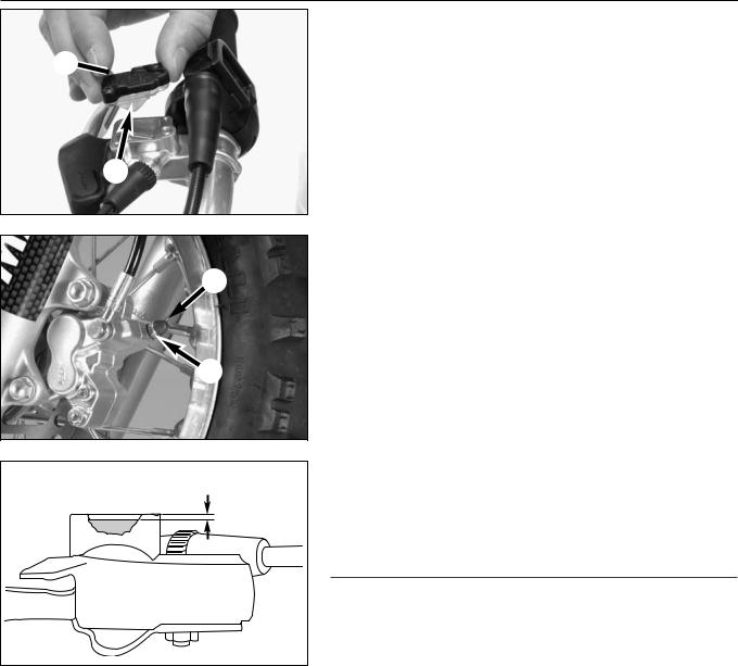
Changing front brake fluid (not Mini Adventure)
–Move the hand brake cylinder into horizontal position.
–Disassemble the cover 1 together with the rubber boot 2 from the brake fluid reservoir.
–Press the brake caliper pistons all the way back.
–Use a syringe to extract the used brake fluid and add fresh DOT 5.1 brake fluid (Motorex Brake Fluid DOT 5.1).
–Use a commercial extractor (shop equipment) to extract the used brake fluid out of the system through the bleeder screw 3 on the brake caliper. Make sure the brake fluid reservoir is always filled with enough fresh brake fluid.
–Tighten the bleeder screw 3 and attach the dust cap 4 again.
5 mm |
– Add DOT 5.1 brake fluid (Motorex Brake Fluid DOT 5.1) up to 5 mm under the top edge of the reservoir. Remount the rubber boot, cover and screws.
–Wash off any overflowing or spilled brake fluid with water.
–Actuate the hand brake lever until you feel the point of pressure.
! |
CAUTION |
! |
– NEVER USE DOT 5 BRAKE FLUID. IT IS BASED ON SILICONE OIL AND DYED PURPLE. GASKETS AND BRAKE HOSES WILL BE DAMAGED IF DOT 5 BRAKE FLUID IS USED.
– BRAKE FLUID CAN CAUSE SKIN IRRITATIONS. AVOID COMING INTO CONTACT WITH THE SKIN OR EYES. IF BRAKE FLUID SPLASHES INTO YOUR EYES, RINSE THOROUGHLY WITH WATER AND CONSULT A DOCTOR.
– MAKE SURE NO BRAKE FLUID COMES INTO CONTACT WITH PAINTED PARTS SINCE BRAKE FLUID WILL CORRODE THE PAINTWORK!
– ONLY USE CLEAN, NEW BRAKE FLUID FROM TIGHTLY SEALED CONTAINERS.
Art.-Nr. 3.206.028 -E
Repair manual KTM MINI 50 air/liquid cooled
|
|
2-6E |
|
Changing rear brake fluid (50 SX, 50 Supermoto) |
|
|
– Move the vehicle in a vertical position. |
|
1 |
– |
Disassemble the cover 1 together with the rubber boot 2 from the |
|
||
|
|
brake fluid reservoir. |
2 |
– |
Press the brake caliper pistons all the way back. |
–Use a syringe to extract the used brake fluid and add fresh DOT 5.1 brake fluid (Motorex Brake Fluid DOT 5.1).
 3
3
 15 mm
15 mm
–Completely remove the bleeder screw 3 .
–Extract the old brake fluid from the system using the bleeder syringe 503.29.050.000. Always make sure that the brake fluid reservoir is filled with sufficient fresh brake fluid.
–Mount the bleeder screw 3 .
–Add DOT 5.1 brake fluid (Motorex Brake Fluid DOT 5.1) up to 15 mm under the top edge of the reservoir. Remount the rubber boot, cover and screws.
–Wash off any overflowing or spilled brake fluid with water.
–Actuate the foot brake lever until you feel the point of pressure.
! |
CAUTION |
! |
– NEVER USE DOT 5 BRAKE FLUID. IT IS BASED ON SILICONE OIL AND DYED PURPLE. GASKETS AND BRAKE HOSES WILL BE DAMAGED IF DOT 5 BRAKE FLUID IS USED.
– BRAKE FLUID CAN CAUSE SKIN IRRITATIONS. AVOID COMING INTO CONTACT WITH THE SKIN OR EYES. IF BRAKE FLUID SPLASHES INTO YOUR EYES, RINSE THOROUGHLY WITH WATER AND CONSULT A DOCTOR.
– MAKE SURE NO BRAKE FLUID COMES INTO CONTACT WITH PAINTED PARTS SINCE BRAKE FLUID WILL CORRODE THE PAINTWORK!
– ONLY USE CLEAN, NEW BRAKE FLUID FROM TIGHTLY SEALED CONTAINERS.
Checking brake pads and brake disks
– See Owner's Manual
|
3-1E |
REMOVING AND REFITTING ENGINE |
3 |
INDEX |
|
REMOVING THE ENGINE . . . . . . . . . . . . . . . . . . . . . . . . . . . . . . . . . . . . . . . . . |
.3-2 |
INSTALLING THE ENGINE . . . . . . . . . . . . . . . . . . . . . . . . . . . . . . . . . . . . . . . . |
.3-4 |
Art.-Nr. 3.206.028-E
Repair manual KTM MINI 50 air/liquid cooled
Art.-Nr. 3.206.028-E
Repair manual KTM MINI 50 air/liquid cooled
3-2E
1
2
3
4
 5
5
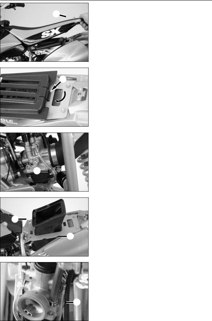
Removing the engine
NOTE: the following steps are shown on a model with LC-engine, on a model with AC-engine a few works are not necessary like draining coolant liquid, removing and mounting the radiator and the radiator shield, bleeding the cooling system.
Clean the entire vehicle thoroughly before removing the engine.
To avoid burns, allow the motorcycle to cool before starting to work.
–Jack up the motorcycle on a sturdy work stand.
–Turn quick release 1 on the seat 180°, lift back of seat slightly and pull back.
–Remove the cover of the air filter by reaching through the recess in the panel and pushing the locating tab 2 forwards with your finger.
–Remove air filter element.
–Loosen hose clamp 3 on the air filter box of the carburetor and remove air filter box.
–Pull air filter box 4 up through the retaining bracket 5 by deforming it.
– Close fuel cock and disconnect fuel hose 6 from the carburetor.
 6
6
3-3E
1
2
 3
3
4
 5
5
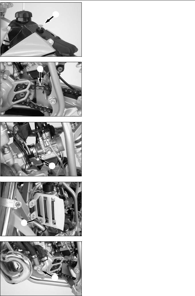
–Loosen retaining bolt on tank 1 and remove from tank together with the rubber grommet.
–Lift tank from the frame.
– Open chain joint 2 and remove chain.
– Loosen hose clamp 3 of the intake flange on the carburetor, pull carburetor back and swing to the side.
NOTE: if the carburetor is not being serviced, it does not need to be removed - the carburetor openings should however be covered with a clean cloth and the gasoline drained from the float chamber.
– Remove radiator shield on the right and left 4.
–Unbolt radiator cap, open drain plug 5 and allow cooling fluid to drain into a receptacle. Then remount the drain plug with a new sealing ring and tighten (5 Nm/4 ft.lb).

Art.-Nr. 3.206.028 -E
Repair manual KTM MINI 50 air/liquid cooled
3-4E
2
 1
1
1
3
–Loosen hose clamp 1 and pull both hoses from their connections.
–Unbolt radiator retaining bolt 2 and laterally remove radiator with water hoses from the frame.
– Carefully pull socket connector 3 apart.
4
4
 6 5
6 5
7
8
–Detach both exhaust springs 4 with a suitable wrench, remove springs.
–Unbolt the exhaust bracket on the right and pull exhaust off towards the front.
– Loosen engine mounting bolts 5 and 6, lift engine from the frame.
Installing the engine
–Lift engine into the frame and fasten with bolt 5 (M8x65 with nut) and 2 bolts 6 (M8x55).
–Tighten bolts to 30 Nm (22 ft.lb).
–Mount exhaust, insert springs 4 and tighten bolt for exhaust bracket M6x15 on the right.
–Carefully connect socket connector 3.
–Position radiator in the frame and tighten the radiator retaining bolts 2 (M6x10 with washer 18/6,5/1,5) to 10 Nm (7 ft.lb). Connect hoses and tighten hose clamps 1.
–Fill cooling liquid (total filling amount approx. 0,5 liter).
–Mount radiator shield on the right and left.
NOTE: bolts 7 (M6x10) are bolted onto the side of the frame, bolt 8 (M6x15) is bolted into the radiator bracket.
Loading...