


OWNER'S MANUAL 2008
1190 RC8 EU
1190 RC8 AUS/UK
1190 RC8 FR
1190 RC8 JP
ART. NO. 3211250en
DEAR KTM CUSTOMER |
1 |
Congratulations on your decision to purchase a KTM motorcycle. You are now the owner of a state-of-the-art sports motorcycle that will give you enormous pleasure if you service and maintain it accordingly.
We wish you great pleasure riding the vehicle!
Please enter the serial numbers of your vehicle below.
Chassis number/type label ( S. 16) |
Dealer's stamp |
Engine number ( S. 17)
Key number ( S. 16)
The owner's manual corresponded to the latest state of this series at the time of printing. However, it is never possible to exclude small deviations arising from further development in design and construction.
All specifications are non-binding. KTM Sportmotorcycle AG in particular reserves the right to modify or delete technical specifications, prices, colors, forms, materials, services, designs, equipment, etc., without prior notice and without specifying reasons, to adapt these to local conditions, as well as to stop production of a particular model without prior notice. KTM accepts no liability for delivery options, deviations from illustrations and descriptions, as well as printing and other errors. The models portrayed partly contain special equipment that does not belong to the regular scope of delivery.

DEAR KTM CUSTOMER |
2 |
© 2008 by KTM-Sportmotorcycle AG, Mattighofen Austria All rights reserved
Reproduction, even in part, is permitted only with the express written permission of the copyright owner.
ISO 9001(12 100 6061)
Within the meaning of the international quality management standard ISO 9001, KTM uses quality assurance processes that lead to the maximum possible quality of the products.
Issued by: TÜV Management Service
KTM-Sportmotorcycle AG
5230 Mattighofen, Austria
CONTENTS |
3 |
MEANS OF REPRESENTATION ............................................... |
7 |
IMPORTANT NOTES............................................................... |
8 |
VIEW OF VEHICLE................................................................ |
12 |
View of vehicle, front left side............................................ |
12 |
View of vehicle, rear right side ........................................... |
14 |
LOCATION OF SERIAL NUMBERS ......................................... |
16 |
Chassis number/type label................................................. |
16 |
Key number ..................................................................... |
16 |
Engine number................................................................. |
17 |
Fork part number.............................................................. |
17 |
Shock absorber part number.............................................. |
18 |
Steering damper part number ............................................ |
18 |
OPERATING ELEMENTS....................................................... |
19 |
Clutch lever ..................................................................... |
19 |
Hand brake lever .............................................................. |
19 |
Light switch ..................................................................... |
20 |
Headlight flasher switch.................................................... |
20 |
Flasher switch.................................................................. |
21 |
Horn button ..................................................................... |
21 |
Ignition/steering lock ........................................................ |
22 |
Emergency OFF switch...................................................... |
22 |
Electric starter button ....................................................... |
23 |
Combination instrument - overview..................................... |
24 |
Combination instrument - function buttons on handlebar ..... |
25 |
Combination instrument - activation and test ...................... |
26 |
display ............................................................................ |
27 |
info display...................................................................... |
28 |
Indicator lamps ................................................................ |
29 |
Notes/warnings on the combination instrument.................... |
30 |
ODO menu....................................................................... |
33 |
FUELDISTANCE menu...................................................... |
34 |
FUELRANGE menu........................................................... |
35 |
DISTANCE TO Next Service menu ...................................... |
36 |
LAPSTOGO menu ............................................................. |
37 |
TOPSPEED menu ............................................................. |
38 |
LAP/BESTLAP/LastLap menu............................................. |
39 |
LAP/BESTLAP/TopSpeed menu.......................................... |
40 |
Total distance menu in Race mode RACEODO..................... |
41 |
SET UP menu .................................................................. |
42 |
CHANGE MODE menu ...................................................... |
43 |
SET CLOCK menu ............................................................ |
44 |
SETTINGS menu .............................................................. |
45 |
SHIFT RPMS menu .......................................................... |
46 |
LAP menu, LAP BLANK T button ....................................... |
47 |
SET NUM LAPS menu ...................................................... |
48 |
TRIP F RESET menu......................................................... |
49 |
UNITS menu.................................................................... |
50 |
SET KM/MILES menu ....................................................... |
51 |
SET °C/°F menu ............................................................... |
52 |
OPTIONS menu................................................................ |
53 |
TPMS menu..................................................................... |
54 |
OPTION OUTERTEMP menu.............................................. |
55 |
Displaying lap times ......................................................... |
60 |
Displaying maximum speed ............................................... |
61 |
Setting ROAD or RACE mode ............................................. |
62 |
Setting the clock with SET CLOCK ..................................... |
62 |
Adjusting shift speed RPM1/2 ........................................... |
63 |
Setting the blank time of the LAP button LAP BLANK T ....... |
65 |
CONTENTS |
4 |
Setting number of laps SET NUM LAPS.............................. |
66 |
Setting fuel reserve display TRIPF RESET........................... |
67 |
Setting kilometers/miles SET KM/MILES............................. |
68 |
Setting temperature unit SET °C/°F .................................... |
69 |
Switching external temperature display on/off...................... |
69 |
Opening the filler cap ....................................................... |
71 |
Closing the filler cap......................................................... |
72 |
Supporting strap............................................................... |
72 |
Seat lock ......................................................................... |
73 |
Tool set ........................................................................... |
73 |
Helmet lock ..................................................................... |
74 |
Passenger footrests........................................................... |
74 |
Shift lever........................................................................ |
75 |
Foot brake pedal .............................................................. |
76 |
Side stand ....................................................................... |
76 |
TIPS ON PUTTING INTO OPERATION .................................... |
77 |
advice on first use ............................................................ |
77 |
Running the engine in....................................................... |
78 |
Loading the vehicle .......................................................... |
79 |
RIDING INSTRUCTIONS ....................................................... |
81 |
checks to be made before putting into operation.................. |
81 |
Starting ........................................................................... |
82 |
starting up ....................................................................... |
83 |
Shifting, riding................................................................. |
84 |
Braking ........................................................................... |
87 |
Stopping, parking ............................................................. |
88 |
Refueling......................................................................... |
89 |
GREASING AND SERVICE TABLE .......................................... |
91 |
Important service tasks to be carried out by an authorized |
|
KTM-RC8 workshop. ......................................................... |
91 |
Important service tasks to be carried out by an authorized |
|
KTM-RC8 workshop. (as additional job) .............................. |
94 |
MAINTENANCE WORK ON CHASSIS AND ENGINE................. |
95 |
Jacking up motorcycle front............................................... |
95 |
Taking front of motorcycle off work stand............................ |
95 |
Jacking up motorcycle rear ................................................ |
96 |
Taking rear of motorcycle off work stand ............................. |
96 |
Fork/shock absorber.......................................................... |
97 |
Adjusting compression damping of fork .............................. |
97 |
Adjusting rebound damping of fork..................................... |
98 |
Adjusting spring preload of fork ......................................... |
99 |
bleeding fork legs ........................................................... |
100 |
Compression damping of the shock absorber ..................... |
101 |
Adjusting the low-speed compression damping of the |
|
shock absorber ............................................................... |
101 |
Adjusting high-speed compression damping of the shock |
|
absorber ........................................................................ |
103 |
Adjusting rebound damping of the shock absorber ............. |
104 |
Adjusting spring preload of shock absorber x................... |
104 |
Steering damper............................................................. |
107 |
Adjusting the steering damper ......................................... |
107 |
Vehicle level .................................................................. |
109 |
Adjusting vehicle level, front x....................................... |
110 |
Adjusting vehicle level at rear .......................................... |
111 |
Footrest position............................................................. |
113 |
Adjusting footrest position............................................... |
113 |
Adjusting shift lever stub................................................. |
116 |
CONTENTS |
5 |
Adjusting shift lever........................................................ |
116 |
Adjusting the footbrake pedal stub ................................... |
120 |
Adjusting the footbrake pedal .......................................... |
121 |
checking for chain dirt .................................................... |
121 |
Cleaning the chain.......................................................... |
122 |
Checking the chain tension ............................................. |
123 |
Adjusting the chain tension ............................................. |
124 |
Checking rear sprocket / engine sprocket for wear .............. |
126 |
Checking chain wear....................................................... |
127 |
Checking chain sliding guard ........................................... |
128 |
Checking front brake discs .............................................. |
128 |
Checking rear brake disc ................................................. |
129 |
Adjusting the basic position of the handbrake lever............ |
129 |
Checking brake fluid level of front brake ........................... |
130 |
Topping up brake fluid of front brake x........................... |
130 |
Brake linings.................................................................. |
132 |
Checking the front brake linings....................................... |
132 |
Checking rear brake fluid level......................................... |
133 |
Topping up rear brake fluid x........................................ |
134 |
Checking the rear brake linings ........................................ |
135 |
Removing front wheel x................................................ |
136 |
Fitting front wheel x..................................................... |
137 |
Removing rear wheel x.................................................. |
138 |
fitting the rear wheel x.................................................. |
140 |
Checking rear hub shock absorbers x.............................. |
143 |
Tire condition checking................................................... |
143 |
Checking tire air pressure................................................ |
145 |
Removing the seat .......................................................... |
146 |
Fitting the seat............................................................... |
146 |
Removing passenger seat ................................................ |
147 |
Fitting the passenger seat ............................................... |
147 |
Mounting helmet lock on vehicle...................................... |
148 |
Removing the battery x................................................. |
148 |
Installing the battery x.................................................. |
150 |
Recharging the battery x............................................... |
151 |
Changing the main fuse .................................................. |
153 |
Changing fuses of individual power consumers .................. |
155 |
Changing the low beam bulb............................................ |
157 |
Change the high beam bulb............................................. |
160 |
Changing the parking light bulb ....................................... |
164 |
Checking headlight adjustment ........................................ |
167 |
Adjusting headlamp range ............................................... |
167 |
Activating/deactivating ignition key .................................. |
168 |
Cooling system ............................................................... |
171 |
Checking the coolant level............................................... |
172 |
Filling the cooling system compensating tank.................... |
173 |
Adjusting basic position of clutch lever............................. |
175 |
Checking fluid level of hydraulic clutch ............................ |
175 |
Correcting fluid level of hydraulic clutch........................... |
176 |
Adjusting gas Bowden cable x....................................... |
177 |
Handlebar height............................................................ |
177 |
Adjusting handlebar height.............................................. |
178 |
Rear frame position ........................................................ |
179 |
Adjusting rear frame position ........................................... |
180 |
Checking engine oil level................................................. |
184 |
Changing engine oil and filter, cleaning oil screen x........ |
185 |
Draining engine oil, cleaning oil screens x...................... |
185 |
Removing oil filter x..................................................... |
188 |

CONTENTS |
6 |
Fitting oil filter x.......................................................... |
190 |
Filling up with engine oil x............................................ |
190 |
Topping up engine oil ..................................................... |
192 |
TROUBLESHOOTING.......................................................... |
194 |
IMMOBILIZER FLASH CODE ............................................... |
197 |
ENGINE CONTROL FLASH CODE......................................... |
198 |
CLEANING......................................................................... |
202 |
Cleaning motorcycle ....................................................... |
202 |
CONSERVATION FOR WINTER OPERATION ......................... |
204 |
Conservation for winter operation ..................................... |
204 |
STORAGE .......................................................................... |
205 |
Storage.......................................................................... |
205 |
Putting into operation after storage .................................. |
206 |
TECHNICAL DATA - ENGINE............................................... |
207 |
Capacity - engine oil ....................................................... |
208 |
Capacity - coolant........................................................... |
208 |
TECHNICAL DATA - ENGINE TIGHTENING TORQUES........... |
209 |
TECHNICAL DATA - CHASSIS ............................................. |
212 |
Lighting equipment ........................................................ |
213 |
Capacity - fuel................................................................ |
214 |
TECHNICAL DATA - FORK................................................... |
215 |
TECHNICAL DATA - SHOCK ABSORBER .............................. |
216 |
TECHNICAL DATA - CHASSIS TIGHTENING TORQUES ......... |
218 |
SUBSTANCES.................................................................... |
221 |
AUXILIARY SUBSTANCES................................................... |
224 |
STANDARDS...................................................................... |
226 |
INDEX ............................................................................... |
227 |
MEANS OF REPRESENTATION |
7 |
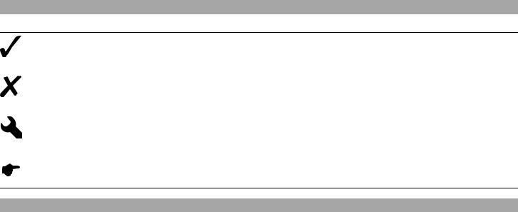
Symbols used
The following explains the meaning of specific symbols.
Identifies an expected reaction (e.g. of an operation or a function).
Identifies an unexpected reaction (e.g. of an operation or a function).
All jobs marked with this symbol require specialist knowledge and technical understanding. In the interests of your own safety, have these jobs done in an authorized KTM-RC8 workshop! There, your motorcycle will be handled optimally by specially trained experts with the necessary special tools.
Identifies a page reference (more information is provided on the specified page).
Formats used
The type formats used are explained here.
Specific name |
Identifies a name. |
Name® |
Identifies a protected name. |
Brand™ |
Identifies a trademark. |
|
|
IMPORTANT NOTES |
8 |
Use definition
KTM sport motorcycles are designed and constructed to meet the normal demands of regular road and race track operation, but not for use on dirt roads.
Info
The motorcycle is authorized for public road traffic in the homologous version only.
Maintenance
A prerequisite for fault-free operation and avoiding premature wear is compliance with the maintenance, care and adjustments to the engine and chassis described in the service manual. Poor suspension settings can cause damage and breakage to chassis components. Using the motorcycle in extreme conditions such as racing can lead to above-average wear to components such as the power train or brakes. It may therefore be necessary to service or replace worn parts before the wear limit shown in the greasing and service table is reached.
Pay special attention to the prescribed running-in times, inspection and maintenance intervals. Proper compliance will contribute considerably to a longer service life of your motorcycle.
Warranty
The maintenance work described in the greasing and service table must be carried out exclusively in an authorized KTM-RC8 workshop and confirmed in the service record, since otherwise any warranty claim is meaningless. No warranty claim can be met for damage resulting from manipulation and/or other changes to the vehicle.
Materials
The fuels and lubricants named in the owner's manual must be used according to specifications.
Spare parts, accessories
In the interests of your own safety, use only spare parts and accessories approved and/or recommended by KTM, and have these fitted in an authorized KTM-RC8 workshop. KTM accepts no liability for other products and any resulting damage.
IMPORTANT NOTES |
9 |
You will find the current KTM PowerParts for your vehicle on the KTM website.
International KTM Website: http://www.ktm.com
Work rules
During assembly, non-reusable parts (e.g. self-locking screws and nuts, seals and seal rings, O-rings, pins, lock washers) must be replaced by new parts.
If a thread lock (e.g. Loctite®) is used for screw connections, be sure to comply with the manufacturer's specific advice on its usage. Parts that you want to reuse following repairs and servicing should be cleaned and checked for damage and wear. Change damaged or worn parts.
Following servicing, the vehicle must be checked for roadworthiness.
Transport
Note
Danger of damage Danger of damage by the vehicle running away or falling over.
–Always place the vehicle on a firm and even surface.
Note
Fire hazard Some components (engine, radiator and exhaust system) get very hot when the engine is running.
–Do not place the vehicle where there are flammable or explosive substances.
–Switch off the engine and remove the ignition key.
–Secure the motorcycle against falling over or running away using straps or other suitable devices.
Environment
Motorcycling is a wonderful sport and we naturally hope that you can enjoy it to the full. However, it can also lead to problems with the environment and conflict with other persons. Responsible behavior in handling the motorcycle can help to avoid such problems and conflicts. To ensure the future of motorcycle sport, make sure you use the motorcycle legally, demonstrate a consciousness for the environment, and respect the rights of others.
IMPORTANT NOTES |
10 |
notes/warnings
Be sure to pay attention to the notes and warnings given here.
Info
Various notes and warning stickers are attached to the vehicle. Do not remove any notes and warning stickers. If these are removed, you or other persons may not recognize potential danger and therefore be liable to injury.
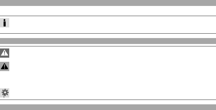
Grades of risks
Danger
Danger of leading to immediate, certain, serious, permanent injuries or death.
Warning
Danger of probable, serious, permanent injuries or death.
Note
Danger of considerable engine or material damage.
Warning
Danger of environmental damage.
Operating instructions
–Be sure to read these operating instructions carefully and completely before taking your first ride. They contain much information and tips that will help you to operate and handle your motorcycle. Only in this way will you find out how to adjust the motorcycle best for your own use and how to protect yourself from injury. These operating instructions also contain important information about servicing the motorcycle.
–The service manual is an important component of the motorcycle and should be passed on to the new owner if the bike is sold.

11
|
VIEW OF VEHICLE |
12 |
|
|
|
|
|
|
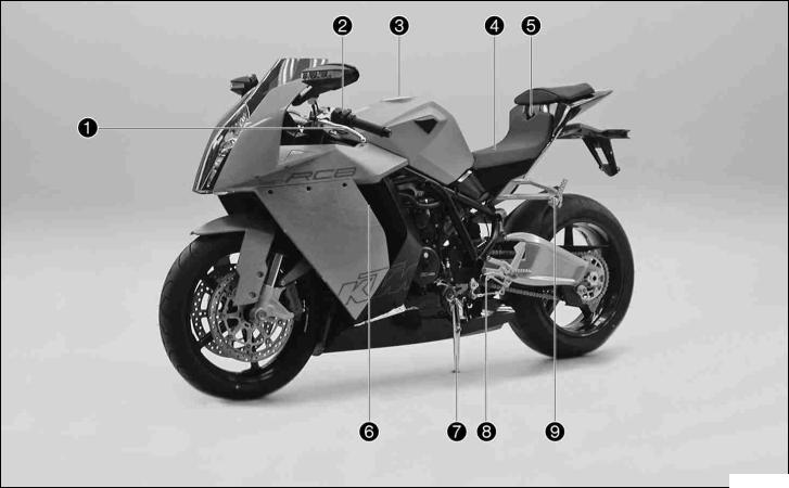
3View.1 of vehicle, front left side |
|
|
700243-10
|
VIEW OF VEHICLE |
13 |
||
|
|
|
|
|
1 |
Clutch lever |
|
|
|
|
|
|
|
|
2 |
Light switch, headlight flasher switch, indicator switch, horn button |
|
|
|
|
|
|
|
|
3 |
Filler cap |
|
|
|
|
|
|
|
|
4 |
Seat |
|
|
|
|
|
|
|
|
5 |
Seat lock |
|
|
|
|
|
|
|
|
6 |
Oil dipstick |
|
|
|
|
|
|
|
|
7 |
Side stand |
|
|
|
|
|
|
|
|
8 |
Shift lever |
|
|
|
|
|
|
|
|
9 |
Passenger footrests |
|
|
|
|
|
|
|
|
|
VIEW OF VEHICLE |
14 |
|
|
|
|
|
|
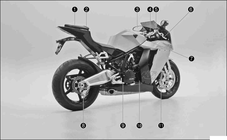
View3.2 of vehicle, rear right side |
|
|
|
|
|
|
700242-10

VIEW OF VEHICLE |
15 |
1Passenger seat
2Supporting strap
3Rear mirror
4Combination instrument
5Emergency OFF switch, electric starter button
6Hand brake lever
7Chassis number, type label
8Rear brake caliper
9Foot brake pedal
10Engine number
11Brake calipers, front
LOCATION OF SERIAL NUMBERS |
16 |
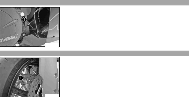
4Chassis.1 number/type label
The chassis number is stamped on the frame behind the steering head on the right.
The type label is on the frame above the chassis number.
700231-01
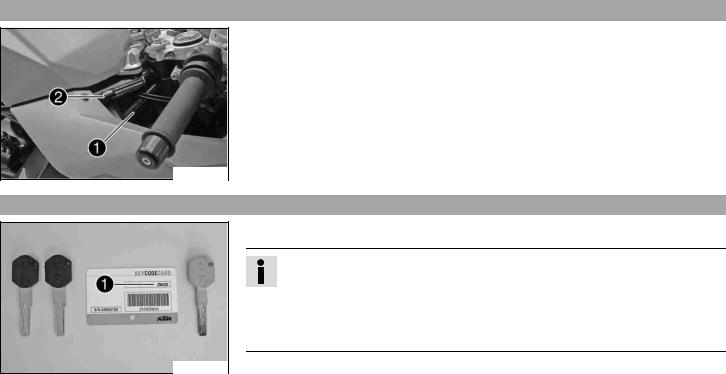
Key4.2 number
The key number Code number can be found on the KEYCODECARD.
Info
You need the key number to order a spare key. Keep the KEYCODECARD in a safe place.
Use the orange programming key to activate and deactivate the black ignition key. Keep the orange programming key in a safe place: it must only be used for learning and programming functions.
700222-01
LOCATION OF SERIAL NUMBERS |
17 |
Engine4.3 number
The engine number is stamped on the right side of the engine.
700223-01
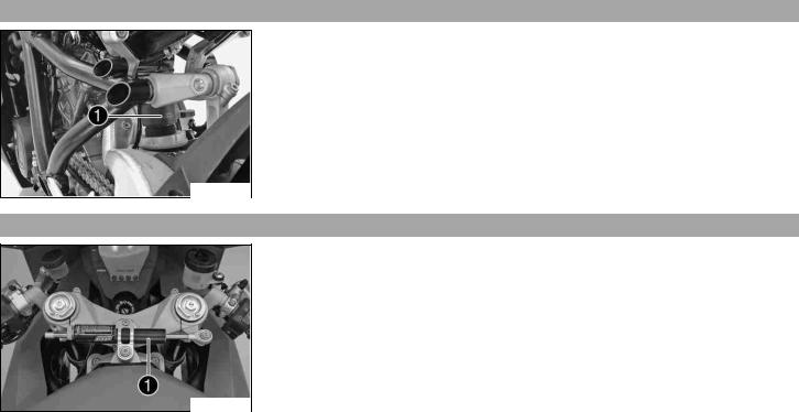
Fork4.4 part number
The fork part number is stamped on the inner side of the fork stub.
700224-01
LOCATION OF SERIAL NUMBERS |
18 |
Shock4.5 absorber part number
The shock absorber part number is stamped on the upper part of the shock absorber above the adjusting ring towards the rear.
700225-01
Steering4.6 damper part number
The steering damper part number is stamped on the top of the steering damper.
700226-01
OPERATING ELEMENTS |
19 |
5Clutch.1 lever
The clutch lever is fitted on the left side of the handlebar.
The clutch is hydraulic and self-adjusting.
700227-01
Hand5.2 brake lever
The handbrake lever is fitted on the right side of the handlebar.
The hand brake lever operates the front brake.
700228-01
OPERATING ELEMENTS |
20 |
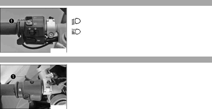
Light5.3 switch
The light switch is fitted on the left side of the handlebar.
Possible states
Low beam on – Light switch is turned downwards. In this position, the low
beam and tail light are switched on.
High beam on – Light switch is turned upwards. In this position, the low beam, the high beam and the tail light are switched on.
700230-13
Headlight5.4 flasher switch
The headlight flasher switch is fitted on the left side of the handlebar.
Possible states
•Headlight flasher switch in neutral position
•Headlight flasher switch pressed – The headlight flasher switch (high beam) is operated in this position.
700232-01
OPERATING ELEMENTS |
21 |
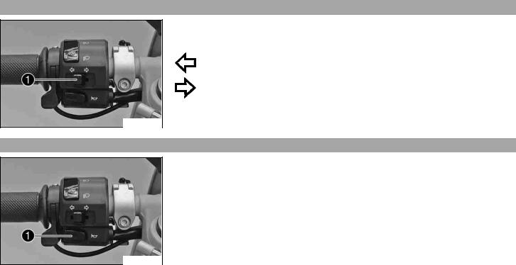
Flasher5.5 switch
The flasher switch is fitted on the left side of the handlebar.
Possible states
Flasher light off
Flasher light, left, on – Flasher switch pressed to the right. The flasher switch returns automatically to the central position after use.
Flasher light, right, on – Flasher switch pressed to the right. The flasher switch returns automatically to the central position after use.
To switch off the flasher light, press the flasher switch towards the switch case.
700230-12
Horn5.6 button
The horn button is fitted on the left side of the handlebar.
Possible states
•Horn button  in neutral position
•Horn button  pressed – The horn is operated in this position.
700230-11
OPERATING ELEMENTS |
22 |
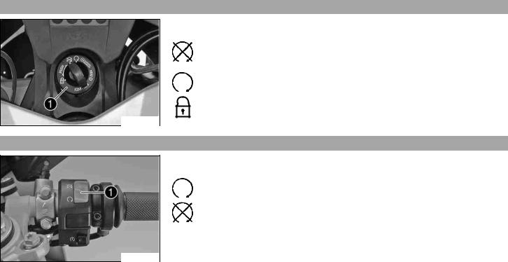
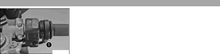
Ignition/steering5.7 lock
The ignition/steering lock is located in front of the upper triple clamp.
Possible states
Ignition off – In this position, the ignition circuit is interrupted, a running engine stops, and a non-running engine will not start. The black ignition key can be removed.
Ignition on – In this position, the ignition circuit is closed, and the engine can be started.
Steering locked – In this position, the ignition circuit is interrupted and the steering locked. The black ignition key can be removed.
700234-01
Emergency5.8 OFF switch
The emergency OFF switch is fitted on the right side of the handlebar.
Possible states
Emergency OFF switch on – This position is necessary for operation, the ignition circuit is closed.
Emergency OFF switch off – In this position, the ignition circuit is interrupted, a running engine stops, and a non-running engine cannot be started.
700229-11
OPERATING ELEMENTS |
23 |
Electric5.9 starter button
The electric starter button is fitted on the right side of the handlebar.
Possible states
•Electric starter button  in neutral position
•Electric starter button  pressed – In this position, the electric starter is operated.
700229-12
OPERATING ELEMENTS |
24 |
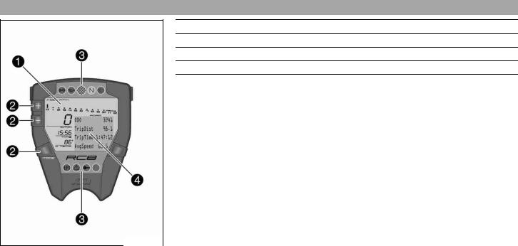
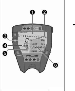
Combination5.10 instrument - overview
1display ( S. 27)
2Function buttons
3Indicator lamps ( S. 29)
4info display ( S. 28)
400430-10
|
OPERATING ELEMENTS |
25 |
|||
|
|
|
|
|
|
|
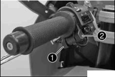
Combination5.11 |
instrument - function buttons on handlebar |
|
|
|
|
|
|
The Mode button is fitted on the handlebar, front left. |
|
|
|
|
|
|
|
|
|
|
|
The Lap button is fitted on the handlebar, rear left. |
|
|
600642-10
|
OPERATING ELEMENTS |
26 |
|||
|
|
|
|
|
|
|
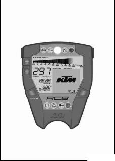
Combination5.12 |
instrument - activation and test |
|
|
|
|
|
|
Activation |
|
|
|
|
|
|
|
|
|
|
|
The combination instrument is activated when the ignition is switched on. |
|
|
|
|
|
Test |
|
|
|
|
|
The segments of the tachometer light up in and switch off in sequence. |
|
|
|
|
|
The speed display counts from 0 to 300 and back. |
|
|
|
|
|
The remaining display segments outside the info display light up briefly. |
|
|
|
|
|
The KTM logo appears in the info display. |
|
|
|
|
|
In ROAD mode, the info display switches to ODO, TripDist, TripTime, AvgSpeed mode. |
|
|
|
|
|
In RACE mode, the info display switches to LAPSTOGO, LastLap, ±Last, ±Best mode. |
|
|
400429-10
|
OPERATING ELEMENTS |
27 |
|||||
|
|
|
|
|
|
|
|
|
display5.13 |
|
|
|
|
|
|
|
|
|
The tachometer displays the engine speed in revolutions per minute (RPM). |
||||
|
|
||||||
|
|
|
The red marking marks the over-rev (excessive speed) range of the engine. |
||||
|
|
|
The speed is displayed in kilometers per hour km/h or in miles per hour Mph. |
||||
|
|
|
The time appears in segment . |
||||
|
|
|
|
|
|
|
|
|
|
|
|
|
|
Info |
|
|
|
|
|
|
|
||
|
|
|
|
|
|
After reconnecting the battery or changing the fuse, the time must be reset. |
|
|
|
|
|
|
|||
|
|
|
The coolant temperature is shown in degrees Celsius or Fahrenheit in segment . |
||||
|
|
|
The info display shows additional information. |
||||
400430-12
|
OPERATING ELEMENTS |
28 |
||||
|
|
|
|
|
|
|
|
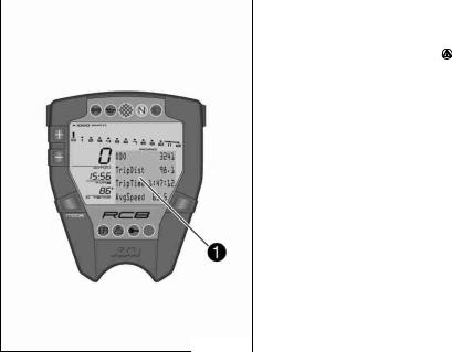
info5.14 |
display |
|
|
||
|
|
|
|
The info display has two menus. |
||
|
|
|
||||
|
|
|
|
Menu 1 is ROAD mode (standard) for riding on public roads. |
||
|
|
|
|
Menu 2 is RACE mode for riding on race courses. It allows riders to time laps themselves. |
||
|
|
|
|
If the general warning lamp |
lights up, the corresponding message is shown periodically |
|
|
|
|
|
in the info display. |
|
|
|
|
|
|
|
|
|
|
|
|
|
Information repeat |
45 s |
|
|
|
|
|
|
|
|
The information shown in the info display can be controlled with the function buttons.
400430-13
 Loading...