


Owner’s Manual
E 2
Precautions
Location
Using the unit in the following locations can result in a malfunction.
•In direct sunlight
•Locations of extreme temperature or humidity
•Excessively dusty or dirty locations
•Locations of excessive vibration
•Close to magnetic fields
Power supply
Please connect the designated AC/AC power supply to an AC outlet of the correct voltage. Do not connect it to an AC outlet of voltage other than that for which your unit is intended.
Interference with other electrical devices
Radios and televisions placed nearby may experience reception interference. Operate this unit at a suitable distance from radios and televisions.
Handling
To avoid breakage, do not apply excessive force to the switches or controls.
Care
If the exterior becomes dirty, wipe it with a clean, dry cloth. Do not use liquid cleaners such as benzene or thinner, or cleaning compounds or flammable polishes.
Keep this manual
After reading this manual, please keep it for later reference.
Keeping foreign matter out of your equipment
Never set any container with liquid in it near this equipment. If liquid gets into the equipment, it could cause a breakdown, fire, or electrical shock.
Be careful not to let metal objects get into the equipment. If something does slip into the equipment, unplug the AC/AC power supply from the wall outlet. Then contact your nearest Korg dealer or the store where the equipment was purchased.
THE FCC REGULATION WARNING (for U.S.A.)
This equipment has been tested and found to comply with the limits for a Class B digital device, pursuant to Part 15 of the FCC Rules. These limits are designed to provide reasonable protection against harmful interference in a residential installation. This equipment generates, uses, and can radiate radio frequency energy and, if not installed and used in accordance with the instructions, may cause harmful interference to radio communications. However, there is no guarantee that interference will not occur in a particular installation. If this equipment does cause harmful interference to radio or television reception, which can be determined by turning the equipment off and on, the user is encouraged to try to correct the interference by one or more of the following measures:
•Reorient or relocate the receiving antenna.
•Increase the separation between the equipment and receiver.
•Connect the equipment into an outlet on a circuit different from that to which the receiver is connected.
•Consult the dealer or an experienced radio/TV technician for help.
Unauthorized changes or modification to this system can void the user’s authority to operate this equipment.
CE mark for European Harmonized Standards
CE mark which is attached to our company’s products of AC mains operated apparatus until December 31, 1996 means it conforms to EMC Directive (89/336/EEC) and CE mark Directive (93/68/EEC). And, CE mark which is attached after January 1, 1997 means it conforms to EMC Directive (89/336/EEC), CE mark Directive (93/68/EEC) and Low Voltage Directive (73/23/EEC).
Also, CE mark which is attached to our company’s products of Battery operated apparatus means it conforms to EMC Directive (89/336/EEC) and CE mark Directive (93/68/ EEC).
Regarding the LCD screen
The LCD screen of the RADIAS is a precision device created using extremely high technology, and careful attention has been paid to its product quality. Although you may notice some of the issues listed below, please be aware that these are due to the characteristics of LCD screens, and are not malfunctions.
•There may be pixels in the screen that are always dark (unlit) or always bright (lit).
•Depending on the displayed content, the brightness of the screen may appear uneven.
•Depending on the displayed content, horizontal stripes of shading may be visible.
•Depending on the displayed content, flickering or moire patterns may be visible.
Data handling
Malfunctions due to incorrect operation may cause the contents of memory to be lost, so we recommend that you save important data on an external data filer (storage device). Please be aware that Korg will accept no responsibility for any damages which may result from loss of data.
*Company names, product names, and names of formats etc. are the trademarks or registered trademarks of their respective owners.
ii
Thank you for purchasing the Korg RADIAS synthesizer/vocoder. To ensure trou- ble-free enjoyment, please read this manual carefully and use the product correctly.
About this manual
How this manual is organized
The RADIAS owner’s manual is organized as follows.
Operation
First read the Operation to learn essential points of operation and basic procedures.
“Introduction” explains the features of the RADIAS, and how its modes and programs are organized.
“Front and rear panel” explains the knobs and buttons of the front panel, and the input/output jacks and switches of the rear panel.
“Setup” explains how to connect the RADIAS to external audio devices, external MIDI devices, computers, pedals, and pedal switches.
“Quick Start” explains basics for playing the RADIAS (listening to the demos, selecting sounds, using the arpeggiator, etc.).
“Editing” explains the basic procedures for editing sound parameters and global parameters, and describes how the main parameters are edited.
Parameter
This section explains the operation of all RADIAS parameters and discusses points of which you should be aware for various settings. The explanations are organized by page for each mode.
Refer to this section when an unfamiliar parameter appears, or when you would like to learn more about the functions.
Appendices
This section provides explanations of MIDI-related topics such as the MIDI messages that the RADIAS can use (control changes etc.), as well as a Voice Name List and other information.
Printing conventions in this manual
Knobs and buttons [ ]
Knobs and buttons on the panel of the RADIAS are enclosed in square brackets [ ].
Parameters shown in the LCD screen “ “
Parameters that appear in the LCD screen are enclosed in double quotation marks “ “.
Bold type
The names of parts of the RADIAS and operating procedures are also printed in bold type.
Procedure steps 1, 2, 3 . . .
Steps in a procedure are printed as 1, 2, 3 . . .
p.
This indicates a page to which you can refer.
Symbols  ,
,
These symbols respectively indicate points of caution and words of advice.
Display screen
The values of parameters appearing in the display screens printed in this manual are only explanatory examples. They will not necessarily match the values shown in the LCD screen of your instrument.
MIDI-related explanations
CC# is used as an abbreviation for Control Change Number.
In MIDI-related explanations, numbers enclosed in square brackets [ ] are in hexadecimal notation.
iii

Table of Contents
Table of Contents
About this manual.................................... |
iii |
Operation ........................ |
1 |
Introduction.................................. |
2 |
Overview.................................................. |
2 |
Program Features: .............................................. |
2 |
Timbre Features: ................................................. |
3 |
Programming Aids:............................................ |
4 |
Modes ................................................................... |
4 |
How a program is structured ..................... |
5 |
Synthesizer .......................................................... |
5 |
Drum kits ............................................................. |
9 |
Front and rear panels ................. |
10 |
Front panel ............................................. |
10 |
Rear panel.............................................. |
14 |
Editing ....................................... |
29 |
Basic editing procedure........................... |
29 |
Editing in the Program Play mode................ |
29 |
Editing in the Program Edit mode ................ |
29 |
Compare function ............................................ |
32 |
Saving an edited program .............................. |
32 |
Loading other timbre sounds/The Template |
|
function.............................................................. |
33 |
Assigning a name............................................. |
34 |
Program parameter editing..................... |
37 |
Synth parameter editing ................................. |
37 |
Editing the effect parameters ......................... |
46 |
Editing the arpeggiator ................................... |
47 |
Step sequencer recording and editing .......... |
50 |
Vocoder editing................................................ |
56 |
Drum parameter editing.......................... |
60 |
Key Zone settings ................................... |
64 |
Envelope Follower settings ...................... |
67 |
Global parameter editing........................ |
68 |
Setup ......................................... |
16 |
Quick Start................................. |
19 |
Turning on the power and adjusting the |
|
volume ................................................... |
19 |
Demo playback....................................... |
19 |
Playing programs – Program Play mode .. |
20 |
Arpeggiator ............................................ |
22 |
Step Sequencer ....................................... |
24 |
Modulation Sequencer............................. |
25 |
Audio In ................................................. |
26 |
Vocoder.................................................. |
27 |
Playing a Drum Kit – Drum Play mode ..... |
28 |
Parameter...................... |
73 |
Program parameters................... |
74 |
1. Name ................................................ |
74 |
P01 NAME ........................................................ |
74 |
2. Program Common .............................. |
74 |
P02 COMMON |
|
(Program Common Parameters).................... |
74 |
P03 TIMBRE |
|
(Timbre Common Parameters) ...................... |
77 |
3. Synth Parameters ............................... |
80 |
P04 VOICE ........................................................ |
80 |
P05 PITCH......................................................... |
81 |
P06 OSC/MIXER.............................................. |
81 |
P07 FILTER ....................................................... |
86 |
P08 AMP (Amplifier)....................................... |
88 |
P09 EG (Envelope Generator) ........................ |
89 |
P10 LFO ............................................................. |
90 |
P11 PATCH (Virtual Patch)............................ |
91 |
iv

Table of Contents
P12 MOD SEQ |
|
(Modulation Sequencer).................................. |
92 |
P13 EQ/FX (Equalizer/Effect)....................... |
94 |
4. ARPEGGIATOR ................................... |
96 |
Front Panel Parameter..................................... |
96 |
P14 ARPEGGIATOR ....................................... |
96 |
5. Step Sequencer................................... |
99 |
Front Panel Parameter..................................... |
99 |
P15 STEP SEQ................................................... |
99 |
6. Vocoder Parameters ......................... |
104 |
P06 CARRIER ................................................. |
104 |
P07 FILTER ..................................................... |
105 |
P08 MODULATOR ........................................ |
105 |
7. Utility ............................................... |
107 |
P16 UTILITY ................................................... |
107 |
Drum parameters...................... |
111 |
1. Name .............................................. |
111 |
P01 NAME ...................................................... |
111 |
2. Drum Common ................................. |
111 |
P02 COMMON............................................... |
111 |
3. Drum Inst ......................................... |
112 |
P05 PITCH....................................................... |
112 |
P06 OSC/MIXER............................................ |
112 |
P07 FILTER ..................................................... |
112 |
P08 AMP (Amplifier)..................................... |
112 |
P09 EG (Envelope Generator) ...................... |
112 |
P10 LFO ........................................................... |
113 |
P11 PATCH (Virtual Patch).......................... |
113 |
4. Utility ............................................... |
113 |
P16 UTILITY ................................................... |
113 |
Global parameters .................... |
114 |
P01 GLOBAL .................................................. |
114 |
P02 MEMORY ................................................ |
115 |
P03 PRELOAD................................................ |
116 |
P04 MIDI ......................................................... |
116 |
P05 MIDI DUMP ............................................ |
117 |
P06 MIDI FILTER........................................... |
118 |
P07 MIDI MAP ............................................... |
118 |
P08 PEDAL/SW............................................. |
119 |
P09 USER SCALE........................................... |
120 |
P10 CATEGORY NAME............................... |
120 |
P11 CALIB [A.SW]......................................... |
120 |
P12 CALIB [A.PEDAL] ................................. |
120 |
Effect guide............................... |
121 |
Overview.............................................. |
121 |
About the effect inputs and outputs............ |
121 |
About the delay time ..................................... |
121 |
Controlling the effect parameters ................ |
122 |
Effect parameters .................................. |
123 |
Appendices .................. |
145 |
About MIDI ........................................... |
146 |
MIDI messages that the RADIAS transmits |
|
and receives..................................................... |
146 |
Sending sound data and other settings (Data |
|
Dump).............................................................. |
150 |
Control change assignments for the RADIAS’ |
|
knobs and buttons.......................................... |
151 |
MIDI driver installation and settings ....... |
152 |
Windows XP users ......................................... |
152 |
Mac OS X users............................................... |
153 |
About the RADIAS and the driver ports ....154 |
|
Troubleshooting .................................... |
155 |
Voice Name List .................................... |
156 |
Program ........................................................... |
156 |
Demo Songs .................................................... |
160 |
Drumkit ........................................................... |
161 |
PCM.................................................................. |
164 |
Templates ........................................................ |
165 |
Specifications and options ..................... |
168 |
MIDI Implementation Chart .................... |
169 |
v

Table of Contents
vi
Operation
Introduction
Front and rear panels
Setup
Quick Start
Editing

Introduction
Overview
The RADIAS Synthesizer/Vocoder is based on Korg’s powerful Multiple Modeling Technology (MMT). It provides an extensive array of cutting-edge synthesis tools and techniques to satisfy the demanding musician, producer or sound designer. The main sound parameters can be edited directly from the front panel. Equipped with 39 knobs, 47 buttons, 16 multi-function keys, a value knob and an informative backlit LCD screen, RADIAS makes it easy to modify the sound as you perform, and to enjoy a versatile range of realtime editing possibilities.
Program Features:
Structure
The RADIAS contains 256 user-editable Program locations. Each program consists of up to four timbres, letting you easily create incredibly rich sounds. You can zone each timbre to a specific range of keys, and play them all from the keyboard, or individual Timbres can be played by the arpeggiator or one of the step sequencers. Additionally, each timbre can be assigned to a specific MIDI channel for four-part multitimbral operation.
Vocoder
The RADIAS features a sophisticated vocoder that can be used not just to simulate the classic vocoder sounds of the past, but also to take advantage of advanced possibilities such as shifting the filter frequencies of each band or adjusting their level and panning to create new and original vocoder sounds.
Korg’s new Formant Motion function uses filter banks to analyze the input signal (the modulator), and records up to seven seconds of formant motion data. By using the play back of this recorded formant motion data, you can create complex moving (or even “talking”) vocoder programs that don’t require any mic input. The RADIAS can hold sixteen sets of formant motion data in internal memory. A front panel [VOCODER] button makes it easy to obtain vocoder sounds.
Audio input/envelope follower
Any audio signal plugged into the INPUT 1 and 2 jacks can be processed in the same way as the internal waveforms, letting you use the RADIAS as an effect processor. The envelope of the audio input signal can also be detected and used as a modulation source in the virtual patch, or used to trigger the sound generator of the RADIAS.
Arpeggiator
The arpeggiator plays the notes you are holding down one at a time, in an up, down, alternating, random or triggered chord fashion - six different types in all. The resolution, key window, swing, and octave range can be set per program; the note, tie and off status can be set for each of the 16 steps, allowing you to create a broad range of melodic and rhythmic patterns.
Step sequencer
Two step sequencers are built-in, allowing you to record simple patterns or phrases. For example you can record a bass line and a drum pattern, and assign two timbres to play these parts, while you play the remaining timbres from the keyboard. Each step sequencer is 32 steps long; however they can be combined to create a single step sequencer that is 64 steps long.
2

Overview
Timbre Features:
Oscillators
Each RADIAS Timbre is built on two oscillators. A total of nine oscillator algorithms are available, including the traditional analog synthesis waves - sine, triangle, pulse (square) and sawtooth - as well as Korg DWGS waves, PCM waves and drum kits, external audio sources and more. Variable Phase Modulation, cross mod, ring mod, sync, waveform shaping and other advanced modulation capabilities allow you to experience more sound-creating flexibility than ever before.
Filters
Two resonating filters are continuously variable from 24dB low pass (four-pole) thru 12dB low pass (twopole), band pass, high pass, up to a “Thru” bypass. For maximum flexibility, the filters can run in series or side-by-side, or even run in a one oscillator per filter arrangement. Filtering can be applied before or after the Amp stage.
LFOs
Twin Low Frequency Oscillators provide a total of five waveforms including Sample/Hold. The speed can be set manually or set as a note value of the internal/external tempo source, and the wave cycle can be sync’d to each key-on message. As with the audio oscillators, these low frequency oscillators also enjoy the benefits of variable waveform shaping.
Envelopes
In addition to the traditional Attack/Decay/Sustain/Release stages, the three enhanced RADIAS envelope generators feature various linear, logarithmic and exponential curve shapes for creating accurate time-vari- able modulation. Velocity and note based parameters provide even more detailed and dynamic articulation.
Effects
The RADIAS provides a two-band equalizer and two insert effects for each timbre, and one master effect for each program. The RADIAS includes 128 editable Insert effect programs, and 128 editable Master effect programs, created using thirty different effect algorithms.
Amp
Traditionally, the Amp section of a synthesizer relates to controlling the volume. The RADIAS adds Drive, “Punch Level” and Wave Shape parameters to the mix. Drive adds controlled harmonic distortion, much like sending too much oscillator signal into another module on a traditional analog synthesizer. Punch Level adds a square wave to the attack portion of the sound for an increase in perceived dynamics. The Wave Shape adds new tonal character to your sound through the Decimator, Hard Clipping and more.
Modulation sequencer
Just as step sequencers provide new pitch data to an oscillator over time, the Modulation Sequencers provide changes in modulation data over time in a way similar to a classic analog sequencer. Each of the three Modulation Sequencers can be applied to any one of 41 different parameters. Modulation sequences can be recorded in step time, or in real time using the Motion Rec function. Modulation sequences are 16 steps long. The output of the modulation sequencer can be sent as a new discreet value at each sequencer step; or the output can be sent as a continuously changing value based on the values assigned to each step.
Virtual patches
The six Virtual Patches (V.PATCH) allow any of 15 modulation sources to be routed to any of 15 modulateable parameters. They function in a similar way to patch cords on a modular analog synthesizer. Five of the sources are MIDI Control Change numbers, which can be set in the Global Mode. This arrangement offers you a high degree of flexibility in creating and controlling sounds.
3

Introduction
Drum kits
A drum kit can be used as one of the four Timbres that make up a Program. The RADIAS contains 32 editable drum kits, and each one may contain up to 16 drum instruments. In addition to playing the drum kit from the keyboard, one of the step sequencers or the arpeggiator can be assigned to play the drum kit, allowing you to create grooves and rhythmic figures within a Program. Using the Drum Play Mode, a drum kit may be played from the keyboard, and edited in real time using the front panel knobs and buttons. One handy addition is the ability to play a drum kit directly from the front panel using the multi-function 16 Keys.
Programming Aids:
Template function
Handy timbre, drum sound, and effect templates are provided as a convenience. When you want to create a timbre, drum sound, or effect setting, simply load the template data that is closest to what you have in mind and then edit it as desired. This is much faster than creating your sounds from scratch. You can also register your own sounds or effect settings as template data.
RADIAS Sound Editor software
Your RADIAS comes with the Korg RADIAS Sound Editor software. By connecting your RADIAS to a computer via USB, you can use this Editor Librarian program to edit, save, store and recall Program, Timbre, FX, Global and parameter data quickly and easily.
Modes
Program Play mode (PROGRAM)
To enter the Program Play mode, press the [PROGRAM] button. This is the mode in which you select and play programs (sounds). As you play, you can use the front panel knobs and buttons to modify the sound, and use the arpeggiator, step sequencer, and modulation sequencer to embellish your performance.
You can also use the vocoder in the Program Play mode. To turn the vocoder on, press the timbre select [VOCODER] button (the button will light or blink, and the letter “V” will appear at the end of the Program name. When the vocoder is on, the functions printed in white with a dark background on the front panel will be active.
Program Edit mode (PROGRAM EDIT)
To enter the Program Edit mode, press the [EDIT/YES] button while in the Program Play mode (vocoder off). In this mode you can edit the parameters of a program while viewing them in the display. You can make detailed changes to the parameter values, and edit parameters lacking a front panel knob or button.
Vocoder Edit mode (VOCODER EDIT)
To enter the Vocoder Edit mode, press the [EDIT/YES] button while you’re in the Program Play mode (vocoder on). In this mode you can edit the vocoder parameters of a program while viewing them in the display. In the Vocoder Edit mode, the functions printed in white with a dark background on the front panel will be active.
Drum Play mode (DRUM)
To enter the Drum Play mode, press the [DRUM] button. In this mode you can select and play drum kits. You can use each of the sixteen keys to play a different drum instrument, and use the front panel buttons and knobs to edit the sound parameters in realtime while you play.
Drum Edit mode (DRUM EDIT)
To enter the Drum Edit mode, press the [EDIT/YES] while you’re in the Drum Play mode. In this mode you can assign drum instruments to create a drum kit, and edit the parameters of a drum instrument while viewing them in the display.
4
How a program is structured
Global mode (GLOBAL)
To enter the Global mode, press the [GLOBAL] button. In this mode you can set the parameters that affect the entire RADIAS, such as tuning and user scales, selecting the functions for the assignable pedal and assignable switch, transmitting MIDI exclusive data dumps, and other MIDI-related settings.
How a program is structured
Each of the RADIAS’ programs consists of four timbres, an arpeggiator, two step sequencers, a vocoder, a master effect, and a envelope follower. A drum kit can also be assigned to one of the timbres.
Synthesizer
Program
Envelope Follower |
|
|
|
|
|
|
Audio In 1 |
|
|
|
|
|
|
Audio In 2 |
|
|
|
|
OUTPUT |
|
|
|
|
|
|
BALANCE |
|
Timbre 1 |
Synth |
|
EQ |
I.FX1/2 |
|
|
|
Synth |
Vocoder |
EQ |
I.FX1/2 |
|
|
|
Synth |
|
EQ |
I.FX1/2 |
|
|
|
Drumkit |
|
EQ |
I.FX1/2 |
Master FX |
MAIN OUTPUT |
|
|
(L/MONO, R) |
||||
|
|
|
|
|
|
|
Drumkit Timbre = Timbre4 |
Vocoder = OFF |
|
|
|
INDIV. OUTPUT |
|
|
|
Carrier |
|
|
|
|
|
|
|
|
|
(L, R) |
|
|
|
InSrc = Timbre2 |
|
|
||
|
|
|
|
|
||
|
|
|
|
|
IntBus (Internal Bus) |
|
Arpeggiator |
Step Seq 1 |
Step Seq 2 |
|
|
|
|
|
Arpeggiator/Step Sequencer |
|
|
|
|
|
Synth |
|
|
|
|
|
|
|
|
|
Audio In 1, 2 |
Filter Routing= Individual |
|
Drive/WS Position |
|
|
||||
IntBus |
OSC1 |
|
|
|
FILTER1 |
= PreAmp |
|
|
|
|
OSC MOD |
MIXER |
|
|
FILTER2 |
|
DRIVE/WS |
AMP |
To Timbre EQ |
|
|
|
|
|
|
|
|
PAN |
|
|
OSC2 |
|
|
|
|
|
|
|
|
|
|
|
|
EG1 |
|
|
|
|
|
|
|
|
|
|
|
|
|
|
|
|
|
|
|
|
KBD TRACK |
|
Free Assign |
|
|
|
NOISE |
|
|
|
|
|
|
|
|
|
|
|
|
|
|
|
|
|
|
|
|
|
|
|
|
|
VIRTUAL PATCH |
|
|
|
|
|
|
|
|
|
|
|
KBD Track |
|
|
|
|
|
|
|
|
|
Velocity |
|
|
EG1 |
EG2 |
EG3 |
LFO1 |
LFO2 |
MIDI 1–5 |
Env.F |
|
|
Free Assign |
|
|
|
|
|
|
|
|
|
SEQ1 SEQ2 SEQ3 |
|
|
|
|
|
|
|
|
|
MOD SEQUENCER |
|
|
|
|
|
|
|
|
5

Introduction
Timbre
A timbre consists of the oscillators (OSC1/OSC2/NOISE), mixer (MIXER), filters (FILTER), amp (AMP), envelope generators (EG), LFOs, virtual patches (VIRTUAL PATCH), modulation sequencers (MOD SEQ), equalizer (EQ), and the insert effects (INSERT FX1/FX2). By editing the parameters of these sections you can create an incredibly diverse range of sounds.
Oscillator (OSC1/OSC2/NOISE)
There are three Oscillator sources; Oscillator 1, Oscillator 2, and the noise generator. Oscillator 1 (OSC1) lets you choose from nine different oscillator algorithms. These include conventional analog synthesizer waveforms, digital synthesizer PCM waveforms and drum PCM waveforms, formant, noise, and even an external audio signal. Oscillator 2 (OSC2) lets you choose from four different oscillator waves - sine, triangle, square, and sawtooth. The noise generator (NOISE) generates white noise. You can use this for a variety of sound shaping situations, such as adding breath noise for a wind instrument sound, or as part of a special effect sound.
For die-hard analog fans, the analog tune feature lets control the amount of simulated oscillator drift that will be applied. Five different portamento curves allow detailed control over glissando passages and gliding between notes. Modulation such as cross-modulation, unison, and VPM (Variable Phase Modulation) can be applied to the analog synthesizer waveforms of Oscillator 1. Oscillator 2 can be used as the modulating oscillator for the sync modulation (SYNC) or ring modulation (RING) that are such classic analog synthesizertechniques. The best elements of SYNC and RING modulation can be combined using a third option: RING SYNC.
Mixer (MIXER)
The mixer adjusts the volume levels of oscillator 1 (OSC1), oscillator 2 (OSC2), and the noise generator (NOISE), and sends the combined signal to the filter (FILTER).
Filter (FILTER1/FILTER2)
The filter section consists of two multi-mode, resonant filters. The two filters can be routed in series or parallel, or even side by side in a “one oscillator per filter” arrangement. The filters adjust the tone of the sound coming from the oscillators by boosting or cutting specific frequency regions. Filter settings will have a major impact on the sound.
By default, envelope generator 1 (EG1) is set to vary the cutoff frequency of the filters over time.
Amp (AMP)
Traditionally, the amp section controls the output volume (AMP) and the panning (PAN), or the position in the stereo field. The RADIAS provides additional features to add more tonal complexity and “edge” to the sound - including Drive, Wave Shape control (DRIVE/WS), and Punch Level. By default, envelope generator 2 (EG2) is set to vary the volume level over time.
Envelope generators (EG1/EG2/EG3)
Envelope generators (EG) are used to apply time-varying change to the sound parameters.
Each EG consists of four parameters: attack time (ATTACK), decay time (DECAY), sustain level (SUSTAIN), and release time (RELEASE). Keyboard dynamics and note number, as well as five time curves, allow for exacting envelope articulation.
Each timbre contains three of these EGs. EG1 is assigned to control the filter cutoff frequency, and EG2 is assigned to control the volume of the amp. You can also use virtual patching (VIRTUAL PATCH) to assign these EGs as envelope sources for other parameters.
LFO section (LFO1/LFO2)
LFO (Low Frequency Oscillator) is used to apply cyclic change to the sound parameters.
Each timbre contains two LFOs, and for each LFO you can choose one of four waveforms. Shape control, key sync and phase controls extend well beyond traditional LFO offerings.
By default, LFO1 is assigned to oscillator 1’s analog algorithms as the knob labelled “Control2”, and LFO2 is assigned to the modulation wheel. You can also make virtual patch settings (VIRTUAL PATCH) to assign the LFOs as modulation sources for other parameters.
6

How a program is structured
Virtual Patch (VIRTUAL PATCH)
The virtual patch section lets you freely assign modulation sources to modulate-able parameters, giving you even more flexibility for creating sounds. You can make six virtual patch assignments in each timbre.
Modulation Sequencer (MOD SEQUENCER)
Using a modulation sequencer, you can apply up to sixteen discrete values (steps) to a modulate-able parameter over time, in a manner similar to vintage analog synthesizers. The modulation sequence can play once, repeat, loop front to back, etc. - providing movement and complexity to the sound. The value can change abruptly at each step, or it can smoothly transition from value to value. The value of each step can be set using the sixteen front panel knobs, or by using the Motion Rec function to record knob movements (changes in parameter values) in realtime. Each timbre provides three sequencers, allowing you to create extremely complex tonal changes.
Equalizer (EQ) and Insert Effects (INSERT FX1/FX2)
Each timbre is equipped with a two-band Equalizer to further control the overall tone. In addition, each timbre also possesses two insert effects. Thirty different effect types are available, and their 128 editable effect program locations to save your favorites. Certain effects can by synced to the tempo of the internal clock that is running the arpeggiator, step sequences, etc. - or to an external MIDI clock. Tempo Sync effects can be conveniently set as note values (Half-note, quarter-note, etc.).
Arpeggiator (ARPEGGIATOR) and Step Sequencer (STEP SEQUENCER)
Each program contains one arpeggiator and two step sequencers. Each timbre in a program can be assigned to be played by the arpeggiator or by one of the step sequences. The arpeggiator lets you choose one of six arpeggio types, and each of the thirty-two steps can be set as a note, tie or rest (off) to create more complex arpeggio patterns. Each step sequencer lets you record a phrase of up to thirty-two steps; both sequencers can be used together to create a single step sequence up to sixty-four steps. The playback of the step sequencer can also be set to transpose based on the notes being played on the keyboard (or via MIDI).
Master effect (MFX)
Each program contains one master effect.
You can use this to apply a reverb or delay effect to the overall combined sound of the program including the processing applied by the insert effects of each timbre, adding the final touch to the complete program. You can choose from thirty different effect types, and 128 editable effect programs.
Envelope follower
In electronic music terms, an envelope is the “shape” of a sound’s change in volume level from start to finish. Each program contains an envelope follower, which generates a changing modulation source based on the envelope of an external audio signal or an internally bussed sound. This detected envelope can also be used to generate note-on/off events.
7
Introduction
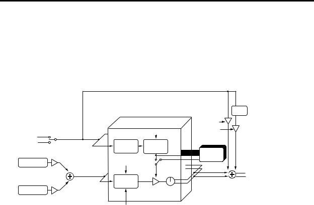
Vocoder (VOCODER)
A vocoder is available in every program The RADIAS’ vocoder contains 16 stereo bands.
A vocoder applies the spectral character of the “modulator” (e.g., a signal received from the INPUT 2 jack) to the “carrier” (e.g., the sound of a timbre or a signal received from the INPUT 1 jack).
The most popular way to use this is to input your voice from a mic connected to the INPUT 2 jack, creating the impression that an instrumental sound is “talking.”
Vocoder
Audio In 2
IntBus
LEVEL
Carrier InSrc1
Carrier InSrc2
LEVEL
Band16 |
|
DIRECT |
|
|
|
LEVEL |
|
Band1 |
E.F. SENSE |
HPF |
|
LEVEL |
|||
|
|
||
ANALYSIS |
ENVELOPE |
|
|
FILTER |
FOLLOWER |
FORMANT |
|
|
|
||
|
|
MOTION DATA |
|
RESONANCE |
MODULATOR |
||
|
|||
|
SELECT |
||
SYNTHESIS |
|
|
|
FILTER |
|
|
|
|
Band. LEVEL |
PAN |
|
CUTOFF (FC MOD) |
|
|
|
FORMANT SHIFT |
|
|
|
HPF
 To Carrier InSrc1 Timbre EQ
Vocoder section (VOCODER)
The vocoder divides the audio spectrum into “bands”. In the RADIAS, the vocoder uses 16 bands. There are actually two sets of 16 bands; the first is used to analyze the tonal characteristics of one sound (the Modulator), and the second set is used to apply the same characteristics to another sound (the Carrier). Each analysis band contains a bandpass filter and an envelope follower. Each synthesis band contains a band pass filter whose output is controlled by the matching envelope follower in the analysis band.
The modulator’s audio signal is sent through the sixteen bandpass filters (the analysis filters), and the envelope follower detects the volume envelope (change over time) for each of these frequency bands.
The carrier’s audio signal is sent through the other set of sixteen bandpass filters (the synthesis filters), and the envelope detected from each analysis filter is applied to each synthesis filter to modulate the sound, producing the impression that the carrier sound is “talking” (the typical vocoder effect).
You can use the “FORMANT SHIFT” and “CUTOFF” parameters to shift the frequencies of the carrier bandpass filters. This will raise or lower the frequency response while preserving the character of the modulator, creating major changes in the sound.
Carrier (CARRIER)
A sawtooth wave (SAW) or other waveform rich in overtones is the best choice for the carrier. As the carrier, you can use a combination of two sources (IN SOURCE 1 and IN SOURCE 2). One of the timbres can be selected as IN SOURCE 1, and either an external input (the INPUT 1 jack) or an internally bussed sound (program output) can be selected as IN SOURCE 2.
Modulator (MODULATOR)
Most commonly, you will input your voice as the modulator, but interesting results can also be obtained by inputting a rhythm sound as the modulator waveform. You can use either an external input (INPUT 2 jack) or an internal bus (program output) as the modulator.
There is also a Formant Motion function that lets you record Formant Motion Data to capture the moving characteristics of a voice or other sound, and use this data to drive the vocoder.
8
How a program is structured
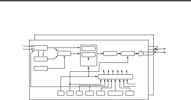
Drum kits
Drumkit
Audio In 1, 2
IntBus
Drum Inst. 16 |
|
|
|
|
|
|
|
Drum Inst. 01 |
|
|
|
|
|
|
|
Filter Routing= Individual |
|
Drive/WS Position |
|
||||
OSC1 |
|
|
|
FILTER1 |
= PreAmp |
To Timbre EQ |
|
|
MIXER |
|
|
|
|
|
|
OSC MOD |
|
|
FILTER2 |
|
DRIVE/WS |
AMP |
|
|
|
|
|
|
|
PAN |
|
OSC2 |
|
|
|
|
|
|
|
|
|
|
EG1 |
|
|
|
|
|
|
|
|
|
|
|
|
|
|
|
|
KBD TRACK |
|
Free Assign |
|
NOISE |
|
|
|
|
|
|
|
|
|
|
|
|
|
|
|
|
|
|
|
|
|
VIRTUAL PATCH |
|
|
|
|
|
|
|
|
KBD Track |
|
|
|
|
|
|
|
Velocity |
|
EG1 |
EG2 |
EG3 |
LFO1 |
LFO2 |
MIDI 1–5 |
Env.F |
Each drum kit consists of sixteen drum instruments. The RADIAS contains thirty-two drum kits.
Each drum instrument consists of OSCILLATOR, MIXER, FILTER, AMP, EQ, LFO, and VIRTUAL PATCH settings, just as with a timbre. ( p.6 “Timbre”)
One of the timbres in a program may be assigned a drum kit. By assigned that timbre to be played by the arpeggiator or one of the step sequences, you can create a program that provides a rhythmic accompaniment to your performance. ( p.64 “Key Zone settings”)
9

Front and rear panels
Front panel
The parameters printed in white characters on a dark background are vocoder parameters.
1 |
5 |
6 |
8 |
9 |
10 |
12 |
11
3  2
2


15
4 |
7 |
13 |
|
|
23 |
14 |
16 |
||
|
20
24
21 |
17 |
18 |
19 |
|
22

1. AUDIO IN
[1/INST] knob
This knob adjusts the input level from the INPUT 1 jack.
[2/VOICE] knob
This knob adjusts the input level from the INPUT 2 jack.
2. VOLUME
[VOLUME] knob
This knob adjusts the overall volume. This knob also adjusts the headphone volume.
3. PHONES
Headphone jack
This jack allows you to listen to the RADIAS through stereo headphones. Connect your headphones to this jack.
4. OCTAVE
[UP], [DOWN] buttons
These shift the pitch of the keyboard and the 16 keys [1]– [16] in one-octave units.
p.22 “Changing the octave”
5. OSCILLATOR 1
WAVE [▲][▼] buttons
These select the waveform for oscillator 1. The LED for the selected waveform will light.
[OSC MOD] buttons
Selects the modulation type. The LED for the selected modulation type will light.
[CONTROL 1] knob
The parameter adjusted by this knob will depend on the selected waveform or modulation type.
[CONTROL 2] knob
The parameter adjusted by this knob will depend on the selected waveform or modulation type.
6. OSCILLATOR 2
[WAVE] button
Selects the waveform for oscillator 2.
The LED for the selected waveform will light.
[OSC MOD] button
Selects the modulation type applied by oscillator 1. The LED for the selected modulation type will light.
[SEMITONE] knob
This knob adjusts the pitch of oscillator 2 in semitone steps.
[TUNE] knob
This knob makes fine adjustments to the pitch of oscillator 2.
10
|
Front panel |
|
|
7. UNISON |
FRMNT SHIFT: When editing vocoder settings, this ad- |
|
justs the amount of formant shift. |
[UNISON - FRMNT REC] button |
|
UNISON: Switches the unison function on/off. FRMNT REC: When editing vocoder settings, this records format motion data for use with the Formant Motion function.
8. MIXER
[OSC1 - SCR1] knob
OSC 1: Adjusts the volume of oscillator 1.
SCR 1: When editing vocoder settings, this adjusts the volume of input 1 (timbre) to the carrier.
[OSC2 - SRC2] knob
OSC 2: Adjusts the volume of oscillator 2.
SCR 1: When editing vocoder settings, this adjusts the volume of input 2 (e.g., external input) to the carrier.
[NOISE] knob
Adjusts the volume of the noise generator.
9. FILTER 1
[CUTOFF - FC OFFSET] knob
CUTOFF: Adjusts the cutoff frequency of filter 1.
FC OFFSET: When editing vocoder settings, this adjusts the cutoff frequency offset value of the synthesis filter.
[RESONANCE] knob
RESONANCE: Adjusts the resonance of filter 1. RESONANCE: When editing vocoder settings, this adjusts the resonance of the synthesis filters.
[TYPE] knob
Selects the type of filter used by filter 1.
A position between markings will produce a character mid-way between the two filter types, allowing you to adjust the proportion of the two types.
[ROUTING - MODULATOR] button
ROUTING: This specifies the routing (combination) of filters 1 and 2.
MODULATOR: When editing vocoder settings, this selects the modulator.
10. FILTER 2
[CUTOFF - THRESHOLD] knob
CUTOFF: Adjusts the cutoff frequency of filter 2. THRESHOLD: When editing vocoder settings, this adjusts the threshold level of the modulator input signal.
[RESONANCE - HPF LEVEL] knob
RESONANCE: Adjusts the resonance of filter 2.
HPF LEVEL: When editing vocoder settings, this adjusts the output level of the HPF (High Pass Filter) applied to the modulator input signal (e.g., the INPUT 2 jack).
[TYPE - FRMNT SHIFT] button
TYPE: Selects the type of filter used by filter 2.
11. FILTER COMMON
[SELECT] button
Selects which filter will be affected by adjusting the EG1 INT knob and KEY TRACK knob.
The LED corresponding to the filter you select will light.
[EG1 INT - FC MOD INT] knob
EG 1 INT: Adjusts the amount of EG1 (depth) that will be applied to the filter cutoff frequency.
FC MOD INT: When editing vocoder settings, this adjusts the depth of modulation applied to the cutoff frequency of the synthesis filter. The modulation source is selected by the [SOURCE - FC MOD SRC] button of the Virtual Patch section.
[KEY TRACK - E.F.SENS] knob
KEY TRACK: Adjusts the amount of keyboard tracking that will be applied to the filter. This allow notes played higher on the keyboard to have a different filter cutoff than notes played lower on the keyboard.
E.F. SENS: When editing vocoder settings, this adjusts the sensitivity of the envelope follower in the vocoder section.
12. AMP
[LEVEL - VC LEVEL] knob
LEVEL: Adjusts the volume of the selected timbre.
VC LEVEL: When editing vocoder settings, this adjusts the output level of the vocoder.
[PAN - DIRECT LEVEL] knob
PAN: Adjusts the pan position of the selected timbre. DIRECT LEVEL: When editing vocoder settings, this adjusts the direct output level of the modulator (e.g., INPUT 2 jack).
[DEPTH] knob
Adjusts the depth of the DRIVE/WS (Wave Shape) effect.
[DRIVE/WS - HPF GATE] button
DRIVE/WS: Selects which function will be applied to the timbre. The LED for the selected function will light. HPF GATE: When editing vocoder settings, this specifies whether the High Pass Frequency gate is enabled or disabled (on or off).
13. V.PATCH (VIRTUAL PATCH)
[SELECT] button
Selects the patch that you will be editing. The LED of the selected patch will light.
[SOURCE - FC MOD SRC] button
SOURCE: Selects the modulation source.
FC MOD SRC (Filter Cutoff Modulation Source): When you’re editing vocoder settings, this selects the modula-
11
Front and rear panels
tion source that will be applied to the cutoff frequency of the synthesis filter.
[DESTINATION] button
Selects the modulate-able parameter that the selected virtual patch will be applied to.
[INTENSITY] knob
Adjusts the amount of modulation that will be applied by the currently selected virtual patch.
14. LFO1/LFO2
[SELECT] button
Selects the LFO waveform. The LED of the selected waveform will light.
[FREQ] knob
[PROGRAM] button
Press this button to enter the Program Play mode.
[DRUM] button
Press this button to enter the Drum Play mode.
[GLOBAL] button
Press this button to enter the Global mode.
[EDIT/YES] button
When you’re in one of the Play modes, press this button to enter the corresponding Edit mode. This button is also used to finish executing functions such as Copy or Write.
In each Edit mode, you can specify a note number or velocity value (e.g., Program Edit mode P03–3: TIMBRE – ZONE tab page “Bottom” or “Top”) by holding down this button and pressing a note on the keyboard.
Specifies the LFO rate. The [SELECT] button will blink in time with the specified rate.
15. DISPLAY & BUTTON
ORIGINAL VALUE LED
When you turn a knob or press a button, this LED will light when the setting matches the value stored in the program.
[EXIT/NO] button
Press this button to return from an Edit mode to the corresponding Play mode. This button is also used to cancel a function such as Copy or Write.
You can switch each timbre on or off by holding down this button and pressing a TIMBRE SELECT [1]–[4] button.
Display
In the Program Play mode, this display shows the program names and program numbers.
In the Drum Play mode, this display shows the drum kit numbers and drum kit names.
In other modes, this display will show the parameters being edited.
[PROGRAM/VALUE] dial
In the Program Play mode, turning this dial selects programs. In the Drum Play mode, this selects drum kits. In other modes turning this dial modifies the value of the parameter selected by the cursor.
[WRITE] button
Use this button to save any edited settings. When you press this button, you will be given the option of saving or not saving; and you will be able to select where the data will be saved.
[COMPARE] button
Returns the values modified by the knobs and buttons to the values stored in the program. Use this when you want to compare the edited sound with the sound that is stored in the program.
PAGE [+] [–] buttons
Use these to switch pages or tab pages.
CURSOR [π/√] [†/®]
Use these to select the parameter you want to edit.
In this manual, the term “cursor” is used when referring to both the [π/√] and [†/®] buttons. If either the [π/√] or [†/®] button is meant, we will refer to the “cursor [π/√] button” or “cursor [†/®] button.”
16. TIMBRE SELECT
[1], [2], [3], [4] buttons
In the Program Play mode, these buttons select the timbre that can be edited from the front panel. By holding down the [EXIT/NO] button while pressing one of the timbre select buttons, you can turn the individual timbre off and on again.
In the Program Edit mode, these buttons select the timbre to be edited.
You can’t select a timbre that is turned off (i.e., whose button is dark). If you want to turn the timbre on, you can either make settings in Program Edit mode, or hold down the [EXIT/NO] button and press a [1]–[4] button to switch the corresponding timbre on or off.
[VOCODER] button
Switches the vocoder on/off. In the Edit mode, press this when you want to edit the vocoder settings.
17. EQ (EQUALIZER)
[HI] knob
Adjusts the level of the high frequency range. Turning this toward the right will boost the level of the high frequency range, and turning it toward the left will decrease the level of the high frequency range.
You can specify the center frequency of the high frequency range in the Program Edit mode P13–1: EQ/FX – EQ tab page.
12

Front panel
[LO] knob
Adjusts the level of the low frequency range. Turning this toward the right will boost the level of the low frequency range, and turning it toward the left will decrease the level of the low frequency range.
You can specify the center frequency of the low frequency range in the Program Edit mode P13–1: EQ/FX – EQ tab page.
18. INSERT FX
[FX1-FX2] button
Selects which insert effect is available for editing. FX1 parameters is selected when this button is dark, and FX2 is selected when this button is lit.
[ON] button
Turns the insert effect selected by [FX1-FX2] on/off. When this button is lit, the effect is on and will be applied.
[EDIT1], [EDIT2] knobs
These knobs adjust various effect parameters.
They will adjust the effect selected by the [FX1-FX2] button. The parameter being adjusted will depend on the type of effect selected.
19. MASTER FX
[ON] button
Switches the master effect on/off. When this button is lit, the effect is on.
[EDIT] knob
Adjusts various master effect parameters. The parameter being adjusted will depend on the effect type you’re using.
20. ARPEGGIATOR/STEP SEQUENCER
[ON] button
This turns the arpeggiator and step sequencers on/off. The arpeggiator and step sequencers are all turned on together
[LATCH] button
This button turns on and off the Latch function that affects the arpeggiator and the step sequencers.
When this function is on (lit), the arpeggiator and/or step sequencers will continue playing even after you take your hand off the keyboard.
The latch setting can be set independently for the arpeggiator and each step sequencer.
[TYPE/STEP REC] button
The function of this button depends on the setting of the [SELECT] button, which can be set to ARPEGGIATOR, STEP SEQ 1, or STEP SEQ 2. If ARPEGGIATOR is selected, pressing this button will scroll through the different arpeggiator types.
If STEP SEQ 1 or 2 is selected, then this button will act as the recording button for that step sequencer. Press this
button to enter record-ready mode; recording will begin when you play the keyboard etc.
[SELECT] button
Selects the arpeggiator or the step sequencer that will be assigned to play the timbre.
[GATE] knob
Adjusts the gate time (duration) specified for each step of the arpeggiator or step sequencer.
[TEMPO] knob
Adjusts the playback tempo of the arpeggiator or step sequencer. This setting will also affect other parameters that are tied to the internal tempo, such as playback speed of a modulation sequencer, an LFO rate, or an effect delay rate.
[TAP TEMPO REST/TIE] button
During playback, you can enter a tempo manually by lightly tapping this button a few times at the desired tempo (Tap Tempo). When you’re recording using the step sequencer, this button allows you to enter ties and rests.
TEMPO LED
This will blink at quarter note intervals of the current tempo.
21. EG1 (FILTER)/EG2 (AMP)
[ATTACK] knob
Adjusts the attack time (rise time from the key on).
[DECAY] knob
Adjusts the decay time (the time from the end of the attack time until the sustain level is reached).
[SUSTAIN] knob
Adjusts the sustain level (the level at which the sound is held).
[RELEASE] knob
Adjusts the release time (the time it takes the sound to completely stop after you release the key).
22. PORTAMENTO
[TIME] knob
Adjusts the way in which portamento is applied.
23. MOD SEQUENCER
[ON] button
Switches the modulation sequencer on/off.
When the button will be lit, the modulation sequencer will be on, and will be active during playback.
[REC] button
Records your knob movements in realtime into the modulation sequencer.
13
Front and rear panels
[SELECT] button
In addition to selecting the function of the 16 knobs above the 16 panel keys, this button also selects which Mod Sequencer is available for editing.
If EDIT is selected, the sixteen knobs can be used to edit the program parameters labelled above each knob. (portamento, EG1, EG2, etc.).
If MOD1, MOD2, or MOD3 is selected, the sixteen knobs will edit the data at the corresponding step of the modulation sequencer.
When you’re editing vocoder settings, the sixteen knobs adjust the level or pan of each synthesis filter (output band).
24. 16 KEYS
[SELECT] button
This button selects the function of the 16 panel keys [1]– [16]. The functions that can be selected will depend on the mode. The LED of the selected function will light. If you select PROGRAM, the sixteen keys can be used to select the programs in the current bank. In the Drum Play mode, the sixteen keys can be used to play drum instruments from the front panel.
If you select TRIGGER, the sixteen keys will toggle individual arpeggiator notes on/off, or indicate the steps of the step sequencer.
If you select PAGE, the sixteen keys will select editing pages or global mode pages.
If you select KEYBOARD, keys [1]–[16] will function as a simple polyphonic MIDI keyboard, and will play the sound of the current program.
The simple MIDI keyboard function of keys [1]– [16] is available only if the dedicated keyboard is not connected.
PROGRAM BANK/TRIGGER [UP], [DOWN] buttons
The function of these buttons will depend on the state of the [SELECT] button.
If the [SELECT] button is set to PROGRAM, these buttons will select the program bank or drum kit (Drum Play mode).
If the [SELECT] button is set to TRIGGER, these buttons will select which step of the arpeggiator or step sequencer will be edited.
If the [SELECT] button is set to PAGE or KEYBOARD, these buttons have no function.
LENGTH LED 1...4
These indicate the length of the arpeggiator or step sequencer that is currently being played or edited. One length indicates sixteen steps.
Rear panel
9 |
8 |
7 |
6 |
5 |
4 |
3 |
2 |
1 |
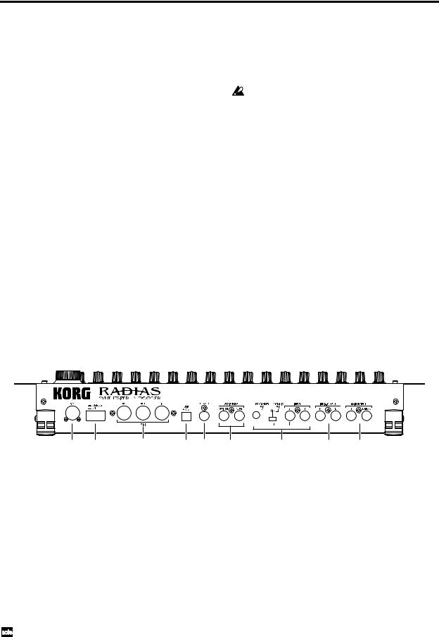
1. MAIN OUTPUT
L/MONO, R jacks
These are the main stereo audio output jacks.
Use these jacks to connect the RADIAS to your powered monitor speakers, stereo amp, mixer, or multitrack recorder, etc. If you’re using a monaural connection, use the L/MONO jack.
2. INDIV. OUTPUT
L, R jacks
These are sub stereo audio output jacks.
The output destination of each timbre can be set to either MAIN OUTPUT or INDIV. OUTPUT. The output destination of each timbre is specified in the Program Edit mode P03–2: TIMBRE – OUT tab page. ( p.78 “P03–2: OUT (Timbre Output)”)
3. INPUT
INPUT 1 jack
You can connect a synthesizer or audio device to this jack. The input signal can be used as the waveform for oscillator 1.
When using the RADIAS as a vocoder, this jack will be the input for the external carrier.
INPUT 2 jack
You can also connect a synthesizer or audio device to this jack. In conjunction with the INPUT 1 jack, the input signal can be used as the waveform for oscillator 1. When using the RADIAS as a vocoder, this jack will be the input for the external modulator.
[SOURCE SELECT] switch
Set this appropriately for the source that’s connected to the INPUT 2 jack.
14
Rear panel
Use the DYNAMIC MIC setting if you’re connecting a mic to the INPUT 2 jack.
Use the LINE setting if you’re connecting a line-level device such as a synthesizer or audio device to the INPUT 2 jack.
Use the CONDENSER MIC setting if you’re connecting the headset mic that came with the RADIAS to the CONDENSER MIC jack.
CONDENSER MIC jack
Connect the mic that came with the RADIAS to this jack.
Do not connect anything other than the included mic to the CONDENSER MIC jack.
4. ASSIGNABLE
PEDAL jack
Connect a foot pedal (expression pedal) to this jack.
SWITCH jack
Connect a foot switch to this jack.
5. TO KYBD (TO KEYBOARD) connector
Connect the RADIAS’ dedicated keyboard to this connector.
6. USB connector
Use a USB cable to connect the RADIAS to your computer via this jack. This connection is used to transmit/ receive MIDI data, and to exchange data with the included RADIAS Sound Editor software.
7. MIDI
MIDI IN connector
This connector receives MIDI messages. Connect it to the MIDI OUT connector or MIDI THRU connector of an external MIDI device.
MIDI OUT connector
This connector transmits MIDI messages. Connect it to the MIDI IN connector of an external MIDI device.
MIDI THRU connector
Received MIDI messages are passed on without change from this connector. Use this when you want to send the same stream of MIDI messages to more than one device.
8. ON/STANDBY
[ON/STANDBY] switch
Turns the power on/off.
9. AC9V
AC9V connector
Connect the included AC/AC power supply here.
15
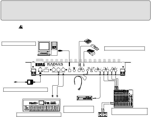
Setup
Make all your connections with the power off (on all units!). If you don’t, you may damage your speaker system or damage your RADIAS and/or other equipment. Please use caution.
ASSIGNABLE SWITCH
6. Connecting your computer
DAMPER
3. Connecting pedals and switches
USB cable
PEDAL
Computer
to AC outlet
Mic
AC/AC power supply
1. Connecting the AC/AC power supply |
MIDI cable |
|
CD player, analog |
|
record player, etc. |
MIDI IN |
MIDI OUT |
|
AUDIO OUTPUT/ |
|
AUX OUT etc. |
5. Connecting the audio inputs – INPUT jacks
4. Connecting external MIDI equipment
Monitor
OUTPUT
INPUT 2. Connecting external audio equipment
Powered monitors, etc.
1. Connecting the AC/AC power supply
Connect the included AC/AC power supply to the RADIAS.
After you’ve connected the AC/AC power supply to the RADIAS, plug it into an AC outlet.
2. Connecting external audio equipment
Connect the OUTPUT jacks of the RADIAS (MAIN OUTPUT, INDIV. OUTPUT) to your audio equipment (e.g., mixer or powered monitors). If you’re using a monaural connection, connect the L/MONO jack.
To take full advantage of the RADIAS’ superb sound, we recommend that you output in stereo.
3. Connecting pedals and switches
Jacks are provided so that you can connect both a foot switch and a foot pedal (both sold separately) to the RADIAS for additional control.
ASSIGNABLE PEDAL jack
By connecting a pedal such as the Korg EXP-2 or XVP-10 to this jack. you can send control messages such as breath control, volume, pan, expression, etc. while keeping your hands free for performing.
The function controlled by the pedal can be specified in the Global mode P08: PEDAL & SW page “A.Pedal.” The factory default setting for the assignable pedal is Expression (Exp Pedal).
p.119 “A.Pedal (Assignable Pedal)”
ASSIGNABLE SWITCH jack
This jack is used for a switch type of pedal such as the Korg PS-1 pedal switch or Korg DS-1H damper pedal. The foot switch can be used for various functions including switching programs, changing octaves, or turning portamento or the arpeggiator on/off. The pedal can be set to act as a momentary pedal, or as a toggle type of switch pedal. The function controlled by the switch can be specified in the Global mode P08: PEDAL & SW page “A.SwFunc.” The factory default setting for the assignable switch is Damper.
16
Setup
Specify the pedal polarity in the Global mode P08: PEDAL & SW page.
p.119 “P08–1: PEDAL/SW”
p.119 “A.SwFunc (Assignable Switch Function)”
4.Connecting external MIDI equipment
The RADIAS can be used as a multitimbral MIDI sound module, or as a controller for other MIDI equipment.
Using the RADIAS as a sound module
If you are using the RADIAS as a sound module, use a MIDI cable to connect the RADIAS’ MIDI IN connector to the MIDI OUT connector of your external MIDI device.
Using the RADIAS as a master keyboard
If you want to play an external MIDI device from the RADIAS’ keyboard, use a MIDI cable to connect the RADIAS’ MIDI OUT connector to the MIDI IN connector of your external MIDI device.
MIDI channel settings – Getting ready to play
If you’re using the RADIAS as a sound module or as a master keyboard, you’ll need to set the RADIAS’ global MIDI channel to match the MIDI channel of the external MIDI device that you’ve connected.
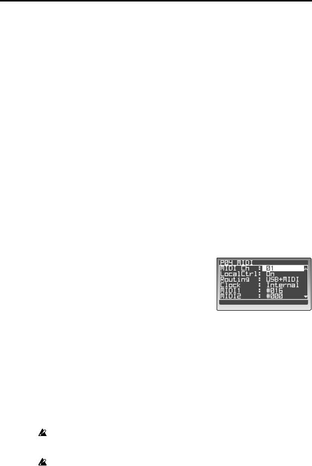
To set the RADIAS’ global MIDI channel, use the Global mode P04: MIDI page “MIDI Ch” setting.
Here’s the procedure for setting the MIDI channel.
1
2
Make sure that the RADIAS is correctly connected to your external MIDI device.
Press the [GLOBAL] button.
You will enter the Global mode. The display will show the Global mode P01: GLOBAL page.
3 Use the 16KEYS [SELECT] button to select PAGE (the
PAGE LED will light), and then press the 16KEYS [4] button.
The display will show the P04: MIDI page.
4 Use the cursor buttons to select “MIDI Ch,” and use the [PROGRAM/VALUE] dial to specify the MIDI channel.
With the factory settings, the global MIDI channel is set to 1. Set this to match the MIDI channel of the external MIDI device you’ve connected.
5 Make sure that the “Routing” setting is set to USB+MIDI or MIDI.
“Routing” specifies whether MIDI data will be transmitted/received via the USB connector or the MIDI connectors. If this is set to USB, use the cursor buttons to select “Routing” and then use the [PROGRAM/VALUE] dial to choose USB+MIDI or MIDI.
With this setting, MIDI data will be transmitted/received via the MIDI connectors.
6
7
Press the [PROGRAM] button to return to the Program Play mode.
Set the MIDI channel of the connected external MIDI device to match the RADIAS’ MIDI channel setting.
For details on how to do this, refer to the owner’s manual of the external device.
Any Global parameters that you edit will revert to their prior state if you turn off the power without writing the changes into memory. If you want to keep your changes, be sure to perform the Write operation. For details on Write, refer to p.68 “5. Saving global parameters (Write).”
A RADIAS program consists of up to four timbres, and you can specify the MIDI channel individually for each timbre. If you’re playing the RADIAS from an external MIDI device, only the timbre(s) set to the same channel as the global channel will produce sound.
17

Setup
5. Connecting the audio inputs – INPUT jacks
You can connect any audio source (synthesizer, CD player, etc.) to the INPUT jacks. Via this connection, the audio coming from this external source can be processed in the same way as the RADIAS’ internal sound generator, or used as the carrier or modulator for the vocoder. You can also use the RADIAS as an effect processor for an external audio source.
For details on these settings, refer to p.26 “Processing an external audio source.”
6. Connecting your computer
The RADIAS provides both MIDI connectors and a USB connector.
Both can transmit and receive MIDI data in the same way. Use the type of connection that’s appropriate for your setup. You’ll need to set the Global mode P04: MIDI page “Routing” appropriately for the connection you use. ( p.116 “Routing”)
Data transfer is faster via the USB connection, so we recommend that you use the USB connector.
If you use MIDI cables to connect the RADIAS to your computer, you’ll need to purchase a separate MIDI interface of the appropriate type for your computer. For details on connecting the MIDI interface to your computer and how to set the MIDI ports, refer to the owner’s manual for your MIDI interface.
If you use an external MIDI sequencer or a sequencer program on the computer you’ve connected, playing the RADIAS’ keyboard will cause notes to be sounded in duplicate if your sequencer’s Echo Back setting is turned on. Go to the RADIAS’ Global mode P04: MIDI page and turn “Local Ctrl” off ( p.116 “Local Control”) so that the internal connection is disconnected. However, be aware that if Local Control is off, there will be no sound if you play the RADIAS’ keyboard when using the RADIAS by itself.
Connections via the MIDI connectors
Use MIDI cables and a MIDI interface to connect the RADIAS to your computer.
Connections via the USB connector
Use a USB cable to connect the RADIAS to your computer.
For details on the appropriate settings to make on the RADIAS so that you can use the RADIAS Sound Editor software, refer to p.71 “Using the included RADIAS Sound Editor software.” For details on installing the software, connecting and adjust the RADIAS’ settings, and using the software, refer to “USB-MIDI driver installation and settings” and the RADIAS Sound Editor software owner’s manual on the CD-ROM included with your RADIAS.
Connecting the RADIAS’ dedicated keyboard RD-KB
For details on how to connect the keyboard, refer to the owner’s manual included with the keyboard RD-KB.
18
Quick Start
The RADIAS contains demo songs, numerous programs, and a wide range of advanced features and functions. For a quick introduction to all this fun, follow along with this Quick Start guide.
Turning on the power and adjusting the volume
By now, you’ve used the preceding pages to hook up your RADIAS correctly, and you’re ready to begin exploring.
Turning the power on/off
Be sure all the other equipment connected to the RADIAS is off before turning the RADIAS on.
1 Press the rear panel [ON/STANDBY] switch to turn on the power.
The start -up screen will appear in the display, and then the display will show the Program Play mode screen. Each time you turn the power on, the RADIAS will be in the Program Play mode.
2 Turn on the other equipment that’s connected to the
RADIAS.
When you’re ready to turn the power off, first turn off the power of the connected equipment, and then press
the [ON/STANDBY] switch on the RADIAS’ rear panel to turn off the power.
Adjusting the volume
Begin with the [VOLUME] knob all the way down. Play a few notes on the keyboard and gradually raise the volume to an appropriate level using the [VOLUME] knob. This knob also adjusts the headphone volume.
Demo playback
The RADIAS contains demo songs that take advantage of its rich sounds and expressive potential.
Playing the demo songs
1 While holding down the [DRUM] button, press the
[GLOBAL] button for approximately one second.
The demo songs will play consecutively, starting with the first song.
During playback, the display will show the song name.
2 You can press the cursor buttons to switch demo songs during playback.
3 Press the [EXIT] button to stop demo playback and return to the Program Play mode.
All Demo Songs: © 2005 KORG Inc. — all rights reserved.
19
Quick Start
Playing programs – Program Play mode
The RADIAS contains a total of 256 programs, organized into sixteen banks (A–P) with sixteen programs in each bank. Here’s how to select and play different programs.
Entering the Program Play mode
The RADIAS defaults to the Program Play mode each time the power is turned on.
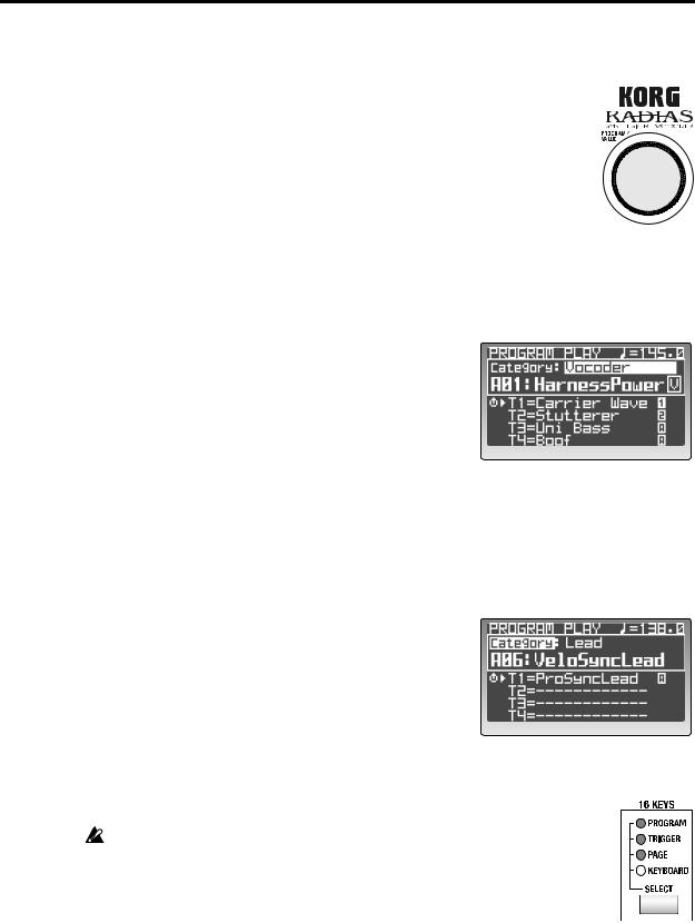
1 Press the [PROGRAM] button.
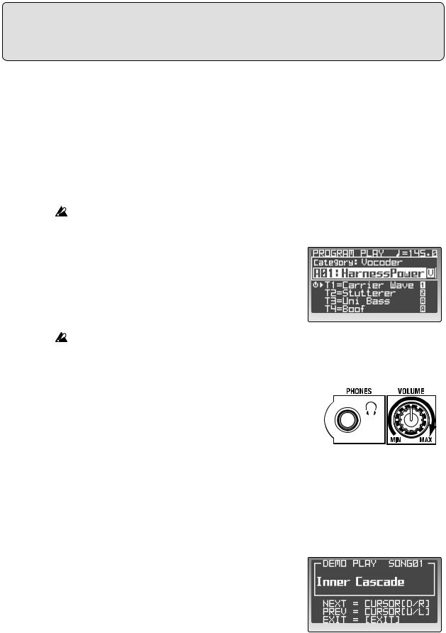
When the RADIAS is in the Program Play mode, the [PROGRAM] button will be lit, and the top line of the display will read PROGRAM PLAY.
The rest of the display will show various information such as the tempo, program category, bank, number, program name, and the names of the timbres used by the program.
Below the program name is a list of the timbre names that are active (turned on) in the current program. Timbres that are off are shown as “------------”.
A  symbol at the left of a timbre name indicates the timbre that can be edited by the front panel knobs and buttons. To specify the timbre that you want to edit from the front panel, use the Program Edit mode P02–1: COMMON – PROG tab page “PanelEdit” setting ( p.75 “PanelEdit”).
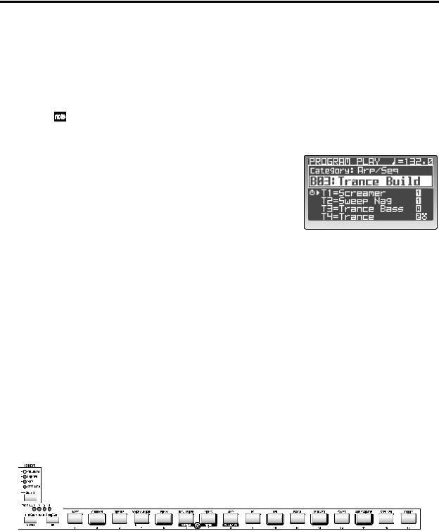
If the arpeggiator is assigned to a timbre, an “ ” symbol is shown at the right of the timbre name. If a step sequencer is assigned to a timbre, a “
 ” symbol (step sequencer 1) or “
 ” symbol (step sequencer 2) is shown at the right of the timbre name.
If a drum kit is assigned to a timbre, a “ ” symbol is shown at the right of the timbre name. In the illustration at the above right, step sequencer 1 is assigned to timbre 1 and timbre 2, the
arpeggiator is assigned to timbre 3, and a drum kit and step sequencer 2 are assigned to timbre 4.
Selecting and playing a program
You can select a program in a variety of ways.
Go ahead and get familiar with selecting and listening to the wide variety of programs provided by the RADIAS.
Using the 16KEYS PROGRAM BANK/TRIGGER [UP]/[DOWN] buttons and [1]–[16] keys
This method lets you quickly select a specific program.
1
2
3
Use the 16KEYS [SELECT] button to choose PROGRAM (the PROGRAM LED will light).
Use the PROGRAM BANK/TRIGGER [UP] or [DOWN] button to select a bank.
There are 16 banks, A–P. Use these buttons to choose a bank.
Use the 16KEYS [1]–[16] to select a program number.
Program numbers 1–16 in each bank correspond to 16KEYS [1]–[16]. This way, you can directly select the desired program from within the bank.
20
Playing programs – Program Play mode
Using the [PROGRAM/VALUE] dial
You can use the [PROGRAM/VALUE] dial to select programs.
Turn the dial toward the right to step through the programs in ascending order, or toward the left in descending order.
Selecting programs by category
Each program can be assigned to a category. You can select programs by from within a category. This is convenient when you want to find a program with the same type of sound.
1 Use the cursor [π/√] button to move the cursor to the category indication in the display.
2 Use the [PROGRAM/VALUE] dial to select the desired category.
The factory-set categories are listed below.
1: Bass |
9: Bell/Decay |
2: Lead |
10: Acoustic |
3: Synth Hard |
11: S.E/Hit/Drum |
4: Synth Soft |
12: Arp/Seq |
5: Motion |
13: Split |
6: Strings/Pad |
14: Audio In |
7: Keyboard |
15: Vocoder |
8: Guitar/Pluck |
16: User |
3
4
Use the cursor [π/√] button to move the cursor to the word “Category.”
Use the [PROGRAM/VALUE] dial to select a program.
You’ll be able to select only programs that are assigned to that category. With the factory settings, sound programs of same variety are assigned to each category.
For details on how to assign a category to a program, refer to p.36 “Assigning a category.”
Playing the RADIAS from the 16KEYS [1]–[16] keys
You can use the 16KEYS [1]–[16] as a keyboard, to play the RADIAS from the front panel.
If the dedicated keyboard is connected, you can't use the 16KEYS [1]–[16] keys to play the sounds.
1 Use the 16KEYS [SELECT] button to choose KEYBOARD (the KEYBOARD
LED will light).
21
Quick Start
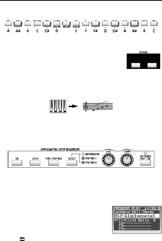
2 Play the RADIAS using the 16KEYS [1]–[16] keys.
The current program will play. The 16KEYS [1]–[16] keys are assigned to the following pitches.
D#
Changing the octave
You can change the range of the 16KEYS [1]–[16] keys by octaves, with a maximum range of a maximum of two octaves up or two octaves down. The LED indicator will show the currently selected octave.
Use the OCTAVE [UP] button or [DOWN] button to shift the pitch in one-octave steps.
Arpeggiator
The arpeggiator detects the notes being played on the keyboard, and automatically plays these notes one at a time in a variety of arpeggiated styles (i.e., arpeggiates the notes of the chord).
Hold down a chord on the keyboard, and it will sound as shown at right (Arpeggio type: Up)
On the RADIAS, you can select one of six arpeggio types, and also specify the duration and spacing of each note in the arpeggio.
Assigning the arpeggiator to a sound
Here’s how to assign the arpeggiator to a specific timbre in a program.
1 Select a program where the arpeggiator isn’t already assigned to a timbre.
Try using a simple bell-type sound with a short sustain.
2 Use the TIMBRE SELECT [1]–[4] buttons to choose which timbre(s) will be played by the arpeggiator.
The button of the selected timbre will blink.
3 Use the ARPEGGIATOR/STEP SEQUENCER
[SELECT] button to select ARPEGGIATOR.
When the arpeggiator is assigned to a timbre, the “ ” indication will appear at the right of the timbre name.
4 Use the ARPEGGIATOR/STEP SEQUENCER [ON] button to turn the arpeggiator on.
The button will light when the arpeggiator is on.
If a step sequencer is assigned to another timbre, the step sequencer will also be turned on at this time.
22
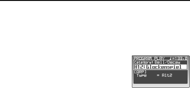
Arpeggiator
5
6
Hold down a chord on the keyboard.
You will hear the arpeggio pattern.
Turn the Latch function on.
Press the [LATCH] button. When Latch is on, the latch button will light.
With the Latch on, the arpeggio will continue playing even after you remove your hand from the keyboard. With the Latch off, the arpeggio will stop playing when you remove your hand from the keyboard. Pressing the [LATCH] button will turn the Latch feature on and off.
7 Use the [TYPE/STEP REC] button to select the arpeggio type.
The display will show the arpeggio type.
The arpeggio type will change each time you press the button.
Press the PAGE [+][–] button or [EXIT/NO] button to return to the previous screen.
8 Use the [TEMPO] knob or the [TAP TEMPO/REST-
TIE] button to adjust the tempo.
Turn the [TEMPO] knob toward the right to speed up the tempo, or toward the left to slow down the tempo.
You can set the tempo manually simply by tapping the [TAP TEMPO/REST-TIE] button several times at regular intervals.
The tempo you specify is shown in the upper right of the display. The TEMPO LED will blink at quarter-note intervals of the specified tempo.
9 Turn the [GATE] knob to adjust the duration of the notes.
Turning the knob toward the right will lengthen the duration of the notes, and turning it toward the left will shorten the duration.
Other settings for the arpeggiator
The arpeggiator also allows you to set the Octave, Key Sync, Scan Zone, Resolution, Swing, and whether or not each step will be heard. For details on these parameters, refer to p.47 “Editing the arpeggiator,” and p.96 “4. ARPEGGIATOR.”
23
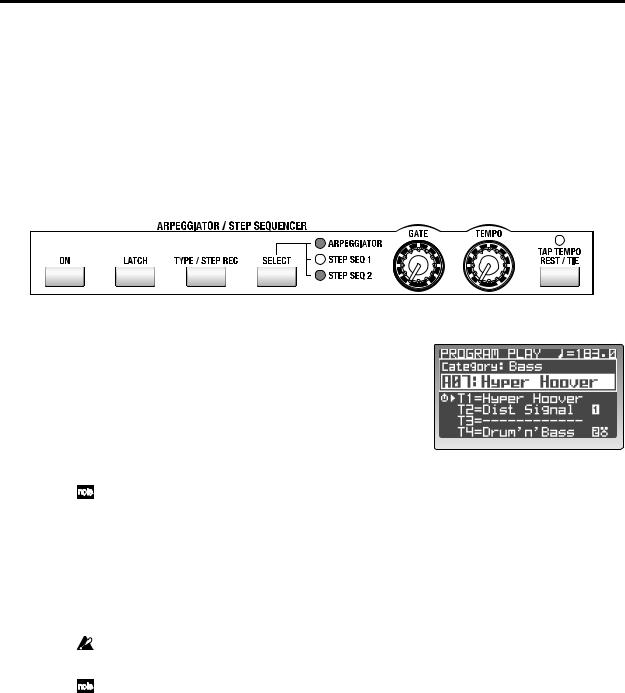
Quick Start
Step Sequencer
You can use the two step sequencers to record and play back a phrase or pattern.
This section explains how to play a step sequence and make some simple edits. For details on recording and editing, refer to p.50 “Step sequencer recording and editing.”
Playing a program using the step sequencer
Some of the factory programs already contain sequence data. For this example, we can select and play one of these programs.
1 Select a program from the “Arp/Seq” category that has a step sequence assigned to one of the timbres.
If a step sequencer is assigned, a “ ” or “
 ” will be displayed at the right of the timbre name.
p.21 “Selecting programs by category”
2 If the ARPEGGIATOR/STEP SEQUENCER [ON] button is not lit, press the [ON] button to make it light.
The button will light when turned on.
If the arpeggiator is assigned to another timbre, the arpeggiator will also be switched on/off at this time.
3 Press the TIMBRE SELECT [1]–[4] button of the timbre being played by the step sequencer.
Select a timbre which has “ ” or “
 ” displayed to the right of the timbre name. The selected timbre button will blink.
4 Hold down a key on the keyboard.
The step sequencer will begin playing.
If the step sequencer does not begin playing, try playing other notes of the keyboard. Some programs may limit the range of notes that triggers the step sequencer.
If you are playing the RADIAS on its own without connecting its dedicated keyboard, you can set the 16KEYS [SELECT] button to KEYBOARD, and use the 16KEYS [1]–[16] to make the step sequencer play.
Other settings for the step sequencers
In addition to the settings mentioned above, you can link step sequencers 1 and 2, adjust the length of the steps, specify the “Run Mode,” transposition, scan zone, resolution, swing, the gate time for each step, velocity and the note numbers that will be played. For details on these parameters, refer to p.50 “Step sequencer recording and editing,” and p.99 “5. Step Sequencer.”
24
 Loading...