


NON-CONTACT 3D DIGITIZER
VIVID 9i/VI-9i
Instruction Manual (HARDWARE)
NOTE
The VI-9i is model name for Europe and the VIVID 9i is model name for other countries. Please note that the VIVID 9i model name is intended only for reference with this manual.

Safety Symbols
The following symbols are used in this manual to prevent accidents which may occur as result of incorrect use of the instrument.
Denotes a sentence regarding safety warning or note.
Read the sentence carefully to ensure safe and correct use.
Denotes a prohibited operation.
The operation must never been performed.
Denotes an instruction.
The instruction must be strictly adhered to.
Denotes an instruction.
Disconnect the AC power cord from the AC outlet.
Denotes a prohibited operation.
The part must never be disassembled.
Denotes an instruction.
Connect the grounding terminal as instructed.
Denotes a sentence regarding safety precaution for laser.
Read the sentence carefully to ensure safe and correct use.
Notes on this Manual
•Copying or reproduction of all or any part of the contents of this manual without KONICA MINOLTA SENSING’s permission is strictly prohibited.
•The contents of this manual are subject to change without prior notice.
•Every effort has been made in the preparation of this manual to ensure the accuracy of its contents. However, should you have any questions or find any errors, please contact a KONICA MINOLTA SENSING-author- ized service facility.
•KONICA MINOLTA SENSING will not accept any responsibility for consequences arising from the use of the instrument.
•Company names and product names which appear in this manual are their trademarks or registered trademarks.
•Contents and display examples given in this manual are subject to change.
About This Manual and Related Documents
The VIVID 9i Non-Contact 3D Digitizer offers rapid, high-precision 3D scanning ideal for imaging of industrial products in a wide range of shapes and configurations. This manual describes the digitizer’s features and operating procedures, and calls attention to relevant precautions.
Please also refer to documents listed below for related information.
Document |
Content |
Polygon Editing Tool |
Explains how to install and use the Polygon Editing software, and gives details |
Instruction Manual |
about all of the software’s features. The Polygon Editing Tool software can be |
|
used to control the operation of VIVID non-contact 3D digitizers, to convert |
|
scanned data into polygon data, to edit and process the scanned data, and to save |
|
the data into standard formats. |
|
|
Polygon Editing Tool |
Explains the basic operations of the Polygon Editing Tool software, with refer- |
Basic Operations Guide |
ence to the VIVID 910 digitizer. |
|
|
Photogrammetry System |
Explains the PSC-1 system, a high-precision alignment system based on photo- |
PSC-1 Instruction Manual |
graphic measurement technology. This system is for use in the VIVID 9i only. |
|
|
Safety Precautions
When using this hardware, the following points must be strictly observed to ensure correct and safe use. After you have read this manual, keep it in a safe place so that it can be referred to easily whenever it is needed.
WARNING |
Failure to adhere to the following points may result |
|
in death or serious injury. |
|
|
|
|
|
Do not use the VIVID 9i in places where flam- |
Do not disassemble or modify the VIVID 9i. |
|
mable or combustible gases (gasoline etc.) are |
Doing so may cause a fire or electric shock. |
|
present. Doing so may cause a fire.
Always use the AC power cord supplied as a |
Do not remove the cover as doing so may cause |
||
standard accessory with the VIVID 9i, and con- |
electric shocks. |
||
nect it to an AC outlet (100-240 V , 50- |
|
||
60 Hz). Failure to do so may damage the VIVID |
|
||
9i, causing a fire or electric shock. |
|
||
|
|
||
Do not bend, twist or pull the AC power cord ex- |
Take special care not to allow liquid or metal ob- |
||
cessively. In addition, do not place heavy items |
jects to enter the VIVID 9i. Doing so may cause |
||
on the AC power cord, or damage or modify it in |
a fire or electric shock. Should liquid or metal |
||
any way. Doing so may cause damage to the AC |
objects enter the VIVID 9i, turn the power OFF |
||
power cord, resulting in fire or electric shock. |
immediately, disconnect the AC power cord |
||
from the AC outlet, and contact the nearest |
|||
|
|
||
|
|
KONICA MINOLTA SENSING-authorized |
|
|
|
service facility. |
|
If the VIVID 9i will not be used for a long time, |
The VIVID 9i should not be operated if dirt or |
||
disconnect the AC power cord from the AC out- |
dust has entered through the vent holes. Doing |
||
let. Accumulated dirt or water on the prongs of |
so may result in a fire. For periodic inspection, |
||
the AC power cord’s plug may cause a fire. If |
contact the nearest KONICA MINOLTA SENS- |
||
there is any dirt or water on the prongs of the AC |
ING-authorized service facility. |
||
|
|||
power cord’s plug, remove it. |
|
|
|
|
|
||
When disconnecting the AC power cord’s plug, |
Never stare into the laser emitting |
||
always hold the plug and pull it to remove it. |
window. |
||
Never pull the AC power cord itself. Doing so |
|
||
may damage the AC power cord, causing a fire |
|
||
or electric shock. In addition, do not insert or |
|
||
disconnect the AC power cord’s plug with wet |
|
||
hands. Doing so may cause electric shock. |
|
||
|
|
||
The VIVID 9i should not be operated if it is |
Do not place a lens, mirror or optical |
||
damaged, or smoke or odd smells are detected. |
element in the passage of the laser |
||
Doing so may result in a fire. In such situations, |
beam. Doing so may converge the la- |
||
turn the power OFF immediately, disconnect the |
ser beam, resulting in damage to your |
||
AC power cord from the AC outlet, and contact |
eyes, burns or fire. To prevent the |
||
above accidents, make sure that a wall |
|||
the nearest KONICA MINOLTA SENSING-au- |
|||
or similar which can block the laser |
|||
thorized service facility. |
|
||
|
beam is located behind the object. |
||
|
|
||
|
|
||
|
|
||
CAUTION |
Falling to adhere to the following points may result in |
||
injury or damage to the instrument or other property. |
|||
Be sure to connect the AC power cord’s plug to an AC outlet that has a grounding terminal.
Make sure that the AC outlet is located near the VIVID 9i and that the AC power cord’s plug can be easily connected and disconnected.
Do not place the instrument on an unstable or sloping surface. Doing so may result in its dropping or overturning, causing injury. Take care not to drop the instrument when carrying it.
1

Laser Caution and Identification Label
Laser Caution and Identification Label
|
|
|
CAUTION |
|
|
|
LASER RADIATION |
|
|
|
DO NOT STARE INTO BEAM |
|
|
|
LASER STRAHLUNG |
|
|
|
NICHT IN DEN STRAHL SEHEN |
|
|
|
MAX 30mW 690nm |
|
|
|
CLASS 2 LASER PRODUCT |
|
|
Complied with IEC Publication 60825-1:1993, Amendment-2:2001 |
|
AVOID |
EXPOSURE |
|
|
Laser |
radiation is emitted |
CLASS 1 LASER PRODUCT |
|
from this aperture. |
|
||
|
|
||
Complies with 21 CFR Chapter 1. Subchopter J.
KONICA MINOLTA SENSING, INC. 3-91, Daisennishimachi, Sakai, Osaka 590-8551, Japan
 manufactured
Warning Label
 WARNING
  WARNUNG
2

Notes On Use
•The VIVID 9i is designed for indoor use only, and should never be used outside.
•This digitized has been calibrated at 20°C. We recommend that you use it environments where ambient temperature is 20°C (68°F).
•Use an AC power source which is within ±10% of the rated voltage.
•The VIVID 9i should be used within a temperature range of 10 to 40°C at a relative humidity of 65% or less.
•Do not use the VIVID 9i in direct sunlight or near sources of heat such as stoves. Doing so will cause the temperature of the VIVID 9i to rise considerably higher than room temperature and may result in malfunctions. Use the VIVID 9i in a well ventilated area and make sure that the ventilation holes of the VIVID 9i are not blocked.
•Do not use the VIVID 9i in extremely dusty or humid areas. Doing so may result in malfunctions.
•Do not subject the VIVID 9i to strong vibration or shocks. Doing so may result in malfunctions.
•When using the VIVID 9i on upper floors of buildings or near high-traffic streets, the instrument and/or measurement subject may vibrate, adversely affecting measurement results.
•Do not allow the digitizer to fall on its side, as it may sustain damaged if knocked over.
•Do not disconnect cords and cables with the POWER switch of the VIVID 9i set to ON “I”. Doing so may result in malfunctions.
•The VIVID 9i has been tested and found to comply with the limits for a Class A digital device, pursuant to Part 15 of the FCC Rules. These limits are designed to provide reasonable protection against harmful interference when the equipment is operated in a commercial environment. This equipment generates, uses, and can radiate radio frequency energy and, if not installed and used in accordance with the instruction manual, may cause harmful interference to radio communications. Operation of this equipment in a residential area is likely to cause harmful interference in which case the user will be required to correct the interference at his own expense.
•The VIVID 9i is a class II instrument specified in IEC Publication 825. Use it according to the instructions given in this manual.
•Do not use the VIVID 9i at altitudes of higher than 2000 m.
•Before using this unit for the first time, and before reusing it following transport, check that the lens is securely in place. If the lens is loose, tighten it in accordance with the tightening instructions included in the lens replacement procedure.
Care On Storage
•The VIVID 9i should be stored in areas with temperatures of between 0 and +40°C. Do not store it in areas subject to high temperature or high humidity or where sudden changes in temperature or condensation are likely to occur. We recommend storing the VIVID 9i around room temperature (20 ± 3°C) with a desiccant (silica gel etc.).
•Do not leave the VIVID 9i inside a closed car or in the trunk of a car. Under direct sunlight, the increase in temperature can be extreme and may result in malfunctions.
•The VIVID 9i should not be stored in areas where there is an excessive amount of dust, cigarette smoke or chemical gas. Failure to adhere to this may result in performance degradation or break-down.
•When shipping the product, use the original packing materials in which the product was shipped. The materials will provide protection against vibrations and impact, and also provide some protection against sudden changes in temperature.
•Lenses that are not in use should be capped and kept in the lens case.
•Before storing this equipment, be sure to attach the receiving lens cap and the laser barrier.
3

Notes On Cleaning
•If the VIVID 9i needs cleaning, wipe with a soft dry cloth. Never use solvents such as thinner or benzene.
•If the lens or laser emitting window is soiled with sand or dust, blow off the dirt using a blower, and wipe them gently with a piece of cleaning paper dampened with cleaning agent.
•In cases of malfunction, do not disassemble the VIVID 9i or attempt to repair it yourself. Contact the nearest KONICA MINOLTA SENSING-authorized service facility.
Notes On Maintenance
To maintain the accuracy of the high-precision Galvano mirror, that plays the most important role in measurement accuracy, a drying agent is used inside the VIVID 9i. Normally, the dehumidification effect of the drying agent lasts more than one year. However, its life varies with the operating and storage environment.
To maintain the designed performance of the VIVID 9i, you are recommended to replace the drying agent once a year. Contact the nearest KONICA MINOLTA SENSING-authorized service facility.
4

Contents |
|
|
Safety Precautions........................................................................................................................................................................ |
1 |
|
Laser Caution and Identification Label........................................................................................................................................ |
2 |
|
Warning Label.............................................................................................................................................................................. |
2 |
|
Notes On Use ............................................................................................................................................................................... |
3 |
|
Care On Storage ........................................................................................................................................................................... |
3 |
|
Notes On Cleaning....................................................................................................................................................................... |
4 |
|
Notes On Maintenance................................................................................................................................................................. |
4 |
|
Chapter 1 Before Using the Instrument |
|
|
Package Contents (Standard Accessories) ........................................................................................................................................... |
8 |
|
Optional Accessories............................................................................................................................................................................. |
10 |
|
System Configuration........................................................................................................................................................................... |
11 |
|
Names and Functions of Parts............................................................................................................................................................. |
12 |
|
Main Body.................................................................................................................................................................................. |
12 |
|
Operation Panel.......................................................................................................................................................................... |
13 |
|
Chapter 2 |
Preparation |
|
Connecting the AC Power Cord.......................................................................................................................................................... |
16 |
|
Connecting the VIVID 9i to a Computer............................................................................................................................................ |
17 |
|
Setting the SCSI ID No.............................................................................................................................................................. |
18 |
|
Setting the Terminator ............................................................................................................................................................... |
19 |
|
Starting and Quitting ........................................................................................................................................................................... |
21 |
|
Starting the VIVID 9i................................................................................................................................................................. |
21 |
|
Quitting the VIVID 9i ................................................................................................................................................................ |
23 |
|
Mounting to the Tripod........................................................................................................................................................................ |
24 |
|
Chapter 3 |
Operation |
|
Replacing the Lens and Field Calibration.......................................................................................................................................... |
28 |
|
Relationship between Measurement Distance and Object......................................................................................................... |
28 |
|
Replacing Procedure .................................................................................................................................................................. |
29 |
|
Field Calibration................................................................................................................................................................................... |
32 |
|
Field Calibration System............................................................................................................................................................ |
32 |
|
Executing Field Calibration ....................................................................................................................................................... |
34 |
|
Adjusting the White Balance ............................................................................................................................................................... |
42 |
|
Displaying the Status Information ...................................................................................................................................................... |
44 |
|
Adjusting the Laser Power and CCD Gain Manually ...................................................................................................................... |
45 |
|
Setting the Scan Mode.......................................................................................................................................................................... |
46 |
|
Chapter 4 |
Appendix |
|
Error Messages ..................................................................................................................................................................................... |
48 |
|
Explanation of Measuring Principle ................................................................................................................................................... |
49 |
|
Measuring Principle ................................................................................................................................................................... |
49 |
|
High-Speed Image Processing Circuit ....................................................................................................................................... |
50 |
|
Time center of gravity and Space center of gravity ................................................................................................................... |
50 |
|
Dimension Diagram.............................................................................................................................................................................. |
51 |
|
Specifications |
......................................................................................................................................................................................... |
52 |
5

6

Chapter 1
Before Using the Instrument
7
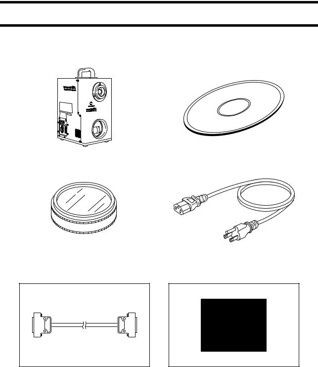
Package Contents (Standard Accessories)
Check that the following standard accessories are present.
|
|
VIVID 9i Main Body |
|
Polygon Editing Tool |
|
|
|
|
|
(with USB protect key) |
|
|
|
|
|
|
|
|
|
|
|
|
|
|
|
|
|
|
|
|
|
|
|
|
|
|
|
|
|
|
|
White Balance Cap VI-A10 |
AC Power Cord |
|
|
|
|
SCSI Cable VI-A20
(Half-pitch, D-sub, 50-pin male plug
– 50-pin male plug)
Laser Barrier
8
|
|
|
|
|
|
|
|
|
|
|
|
|
|
|
|
|
|
|
|
|
|
|
|
|
|
|
|
|
|
|
|
|
|
|
|
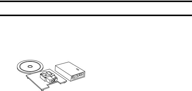
Package Contents (Standard Accessories) |
|
|
|
||
Lens |
|
|
|
|
|
|
|
|
|
|
|
|
|
|
|
|
Field Calibration System |
|
|||||||||||||||||||||||
(3 types, TELE, MIDDLE, WIDE/ |
|
|
|
|
|
|
|
|
|
|
|
|
|
|
|
|
(Field Calibration System, Frame for Calibration |
|
|||||||||||||||||||||||
with Lens Cap) |
|
|
|
|
|
|
|
|
|
|
|
|
|
|
|
|
System, Hex wrench (M5), 4 screws) |
|
|||||||||||||||||||||||
|
|
|
|
|
|
|
|
|
|
|
|
|
|
|
|
|
|
|
|
|
|
|
|
|
|
|
|
|
|
|
|
|
|
|
|
|
|
|
|
|
|
|
|
|
|
|
|
|
|
|
|
|
|
|
|
|
|
|
|
|
|
|
|
|
|
|
|
|
|
|
|
|
|
|
|
|
|
|
|
|
|
|
|
|
|
|
|
|
|
|
|
|
|
|
|
|
|
|
|
|
|
|
|
|
|
|
|
|
|
|
|
|
|
|
|
|
|
|
|
|
|
|
|
|
|
|
|
|
|
|
|
|
|
|
|
|
|
|
|
|
|
|
|
|
|
|
|
|
|
|
|
|
|
|
|
|
|
|
|
|
|
|
|
|
|
|
|
|
|
|
|
|
|
|
|
|
|
|
|
|
|
|
|
|
|
|
|
|
|
|
|
|
|
|
|
|
|
|
|
|
|
|
|
|
|
|
|
|
|
|
|
|
|
|
|
|
|
|
|
|
|
|
|
|
|
|
|
|
|
|
|
|
|
|
|
|
|
|
|
|
|
|
|
|
|
|
|
|
|
|
|
|
|
|
|
|
|
|
|
|
|
|
|
|
|
|
|
|
|
|
|
|
|
|
|
|
|
|
|
|
|
|
|
|
|
|
|
|
|
|
|
|
|
|
|
|
|
|
|
|
|
|
|
|
|
|
|
|
|
|
|
|
|
|
|
|
|
|
|
|
|
|
|
|
|
|
|
|
|
|
|
|
|
|
|
|
|
|
|
|
|
|
|
|
|
|
|
|
|
|
|
|
|
|
|
|
|
|
|
|
|
|
|
|
|
|
|
|
|
|
|
|
|
|
|
|
|
Tripod Attachment Set
(Tripod attachment, Hex wrench (M3), 4 screws)
9
Optional Accessories
When you need to purchase the following optional items, contact a KONICA MINOLTA SENSING-author- ized service facility.
|
|
Rotary Stage Set |
Tripod/Panhead VI-B25 |
|
|
|
(Pan head, Tripod, Ball Adapter) |
|
|
|
|
|
|
|
|
|
|
|
|
|
|
|
|
10
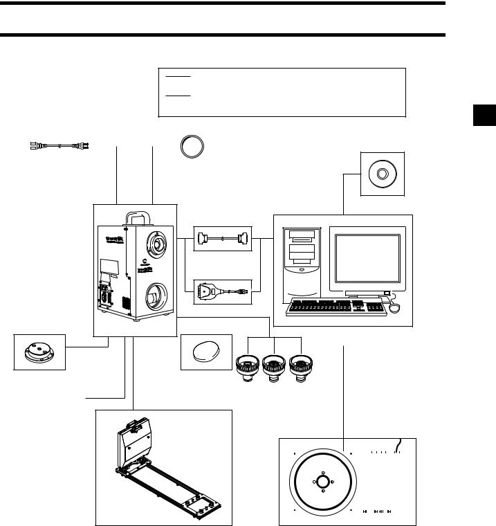
System Configuration
Standard Accessories
Optional Accessories
(A commercially available computer can be used)
|
|
|
|
|
|
|
|
|
|
|
|
|
|
|
|
|
|
|
|
|
AC Power Cord |
|
|
|
White |
Balance Cap |
|
|
|
|
VI-A10 |
|
||
|
|
|
|
|
|
|
|
Polygon Editing Tool |
|
SCSI Cable VI-A20 |
VIVID 9i Main Body |
Computer |
|
Tripod Attachment Set |
Laser Barrier |
3 types of lens
Tripod/Panhead VI-B25
|
|
|
|
|
|
|
|
|
|
|
|
|
|
|
|
|
|
|
|
|
|
|
|
|
|
|
|
|
|
|
|
|
|
|
|
|
|
|
|
|
|
|
|
|
|
|
|
|
|
|
|
|
|
|
|
|
|
|
|
|
|
|
|
|
|
|
|
|
|
|
|
|
|
|
|
|
|
|
|
|
|
|
|
|
|
|
|
|
|
|
|
|
|
|
|
|
|
|
|
Field Calibration System |
|
|
Rotary Stage Set |
||||||||||||||||
11
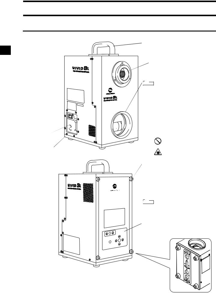
Names and Functions of Parts
Main Body
Power Switch 


AC Power
Connector
SCSI Port 
Handle
Light-Receiving Lens


 Note Please keep the receiving lens cap and the laser barrier place in place when you are not carrying out scanning. Dust and scratches on the laser and lens can ad-
 versely affect scanning precision.
 Laser Emitting Window
 WARNING
A laser beam is emitted from this window.
Do not stare into this window.
Rubber supports
Use when necessary to lean the device on its side for installing the tripod attachment, etc.
 Viewfinder (5.7" LCD)
Displays the lens image and various setup menus.

 Note In rare cases some dot breakup may be visible on the LCD, but this does not indicate a problem with the scan data itself.
 Operation Panel
Used for adjusting the focus and making various settings.
Rubber supports  Support the device.
12
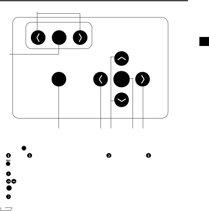
Names and Functions of Parts 
Operation Panel
2
FOCUS
AUTO
1
MENU |
CANCEL |
SELECT |
ENTER
3 4 5 6 7
1 FOCUS AUTO |
.......................... |
Focuses the image automatically. |
|
|
|
2 |
(Near) / |
(Far) ........... |
Focuses the image manually. |
indicates “far” and |
indicates “near”. |
3 ......................................... |
|
|
Press once to display the menu on the viewfinder. Press again to close the |
||
CANCEL |
|
|
menu and return to the monitor image. |
|
|
4 ........................................ |
|
|
Cancels the current operation and returns to the preceding level. |
||
5 |
................................... |
|
Selects an item at the viewfinder. |
|
|
6 ENTER ........................................ |
|
|
Sets the current selection, and moves to the next level (if any). |
||
SELECT |
|
|
Moves to the next level for the item currently selected in the viewfinder. |
||
7 ........................................ |
|
|
|||
Memo
If you wish to carry out a local operation while the unit is in REMOTE mode (while REMOTE is displayed in the viewfinder): Press any key to cancel REMOTE mode, and then press the appropriate keys for the operation you wish to carry out.
(The MENU view may not be displayed even if  is pressed depending on the view currently displayed.)
13

 Names and Functions of Parts
14

Chapter 2
Preparation
15
 Loading...