


 Loading...
Processing
KODAK
Color Print Films,
Module 9
Process ECP-2E
Specifications
©Eastman Kodak Company, 2006

Table of Contents
FILMS AND PROCESS SEQUENCE . . . . . . . . . . . . . . . . . . . . . . . . . . . . . . . . . . 9-1 Designated Films . . . . . . . . . . . . . . . . . . . . . . . . . . . . . . . . . . . . . . . . . . . 9-1 Film Structure. . . . . . . . . . . . . . . . . . . . . . . . . . . . . . . . . . . . . . . . . . . . . . 9-1 Process ECP-2E Steps . . . . . . . . . . . . . . . . . . . . . . . . . . . . . . . . . . . . . . 9-2 Alternative Ferricyanide or UL Bleach Sequence . . . . . . . . . . . . . . . . . . 9-2 Safelights for Darkroom Illumination . . . . . . . . . . . . . . . . . . . . . . . . . . . . 9-2 Film Storage and Handling . . . . . . . . . . . . . . . . . . . . . . . . . . . . . . . . . . . 9-2 Other Film Characteristics . . . . . . . . . . . . . . . . . . . . . . . . . . . . . . . . . . . . 9-2
PROCESSING MACHINE DESIGN AND CONSTRUCTION. . . . . . . . . . . . . . . . . 9-3 Machine Design . . . . . . . . . . . . . . . . . . . . . . . . . . . . . . . . . . . . . . . . . . . . 9-3 Construction Materials . . . . . . . . . . . . . . . . . . . . . . . . . . . . . . . . . . . . . . . 9-6 Filters . . . . . . . . . . . . . . . . . . . . . . . . . . . . . . . . . . . . . . . . . . . . . . . . . . . . 9-8 Crossover Squeegees . . . . . . . . . . . . . . . . . . . . . . . . . . . . . . . . . . . . . . . 9-8 Dryer Cabinet. . . . . . . . . . . . . . . . . . . . . . . . . . . . . . . . . . . . . . . . . . . . . . 9-8 Film Lubrication . . . . . . . . . . . . . . . . . . . . . . . . . . . . . . . . . . . . . . . . . . . . 9-8 Machine Exhaust and Room Ventilation Systems . . . . . . . . . . . . . . . . . . 9-9 Countercurrent Washes . . . . . . . . . . . . . . . . . . . . . . . . . . . . . . . . . . . . . . 9-9
OPERATING SPECIFICATIONS . . . . . . . . . . . . . . . . . . . . . . . . . . . . . . . . . . . . . . 9-9 Mechanical Specifications . . . . . . . . . . . . . . . . . . . . . . . . . . . . . . . . . . . . 9-9 UL Bleach Formulations. . . . . . . . . . . . . . . . . . . . . . . . . . . . . . . . . . . . . . 9-13 Conversion to UL Bleach . . . . . . . . . . . . . . . . . . . . . . . . . . . . . . . . . . . . . 9-13 Drying Specifications . . . . . . . . . . . . . . . . . . . . . . . . . . . . . . . . . . . . . . . . 9-14 Turbulation Specifications . . . . . . . . . . . . . . . . . . . . . . . . . . . . . . . . . . . . 9-14 Wash-Water Flow Rates . . . . . . . . . . . . . . . . . . . . . . . . . . . . . . . . . . . . . 9-15 Stop Wash . . . . . . . . . . . . . . . . . . . . . . . . . . . . . . . . . . . . . . . . . . . . . . . . 9-15 Bleach Wash . . . . . . . . . . . . . . . . . . . . . . . . . . . . . . . . . . . . . . . . . . . . . . 9-15 Final Wash . . . . . . . . . . . . . . . . . . . . . . . . . . . . . . . . . . . . . . . . . . . . . . . . 9-15 Rewashing . . . . . . . . . . . . . . . . . . . . . . . . . . . . . . . . . . . . . . . . . . . . . . . . 9-15
PROCESSING CHEMICALS AND FORMULAS . . . . . . . . . . . . . . . . . . . . . . . . . . 9-16 Packaged Chemicals . . . . . . . . . . . . . . . . . . . . . . . . . . . . . . . . . . . . . . . . 9-16 Bulk Chemicals . . . . . . . . . . . . . . . . . . . . . . . . . . . . . . . . . . . . . . . . . . . . 9-16 Solution Mixing. . . . . . . . . . . . . . . . . . . . . . . . . . . . . . . . . . . . . . . . . . . . . 9-19 Formulas and Analytical Specifications . . . . . . . . . . . . . . . . . . . . . . . . . . 9-20 Storage of Solutions. . . . . . . . . . . . . . . . . . . . . . . . . . . . . . . . . . . . . . . . . 9-27
OPTICAL SOUND PROCESSING . . . . . . . . . . . . . . . . . . . . . . . . . . . . . . . . . . . . . 9-27 Overview . . . . . . . . . . . . . . . . . . . . . . . . . . . . . . . . . . . . . . . . . . . . . . . . . 9-27 Sound Track Operating Specifications. . . . . . . . . . . . . . . . . . . . . . . . . . . 9-27 Sound Track Control . . . . . . . . . . . . . . . . . . . . . . . . . . . . . . . . . . . . . . . . 9-27 MORE INFORMATION . . . . . . . . . . . . . . . . . . . . . . . . . . . . . . . . . . . . . . 9-28
The information contained herein is furnished by Eastman Kodak Company without any warranty or guarantee whatsoever. While Kodak is unaware of any valid domestic patents of others which would be infringed by the methods, formulas or apparatus described herein, the furnishing of this information is not to be considered as any license for inducement of, or recommendation for any action by any party any such action being a matter for independent investigation and decision by such party.
Process ECP-2E Specifications |
-0 |
9 PROCESS ECP-2E SPECIFICATIONS
This module contains specifications describing continuous machine processing of Kodak color print films. The following modules are also used in conjunction with Process ECP-2E. Process ECP-2E differs from Process ECP-2D in that there is no first fix or sound application.
Module 10 |
Effects of Mechanical and Chemical |
|
Variations in Process ECP-2E |
Module 1 |
Process Control |
Module 2 |
Equipment and Procedures |
Module 3 |
Analytical Procedures (for Chemical |
|
Analyses) |
Module 4 |
Reagent Preparation Procedures (for |
|
Chemical Analyses) |
Module 5 |
Chemical Recovery Procedures |
Module 6 |
Environmental Aspects |
FILMS AND PROCESS SEQUENCE
Designated Films
KODAK VISION Color Print Film / 2383
Performance Characteristics and Applications: This film is designed for making projection-contrast prints from camera-original color negatives, duplicate negatives, and internegatives made from color reversal originals. Film 2383 has an ESTAR Safety Base.
For information on color balance, image structure, sensitometric curves, printing conditions, and film storage, see KODAK Publication H-1-2383.
KODAK VISION Premier Color Print Film / 2393
Performance Characteristics and Applications: Like its counterpart KODAK VISION Color Print Film, VISION Premier Color Print Film is coated on a polyester base without rem-jet, for a cleaner process and cleaner screen images. The upper tone scale of VISION Premier Color Print Film is significantly higher in density than KODAK VISION Color Print Film, so shadows are deeper, colors are more vivid, and the image snaps and sizzles on the screen. The toe areas of the sensitometric curves are matched more closely, producing more neutral highlights on projection. Cinematographers can be more creative with lighting and exposure, and still see remarkable results.
For information on color balance, image structure, sensitometric curves, printing conditions, and film storage, see KODAK Publication H-1-2393.
KODAK VISION Color Teleprint Film / 2395 / 3395
Performance Characteristics and Applications: KODAK VISION Color Teleprint Film / 2395 / 3395 is specifically designed for making low-contrast contact or optical prints from camera-original negatives, duplicate negatives, and internegatives. This film has been optimized to produce low contrast positive images that closely match the dynamic range of telecine transfer mediums to produce excellent video images.
Film 2395 / 3395 is coated on a new ESTAR Base featuring proprietary Kodak technology that replaces rem-jet with process-surviving, anti-static layer, and scratchresistant backing layer. This film has an efficient antihalation layer under the emulsion layers, using patented solid particle dyes that are decolorized and removed during processing.
For information on color balance, image structure, sensitometric curves, printing conditions, and film storage, see KODAK Publication H-1-2395.
Film Structure
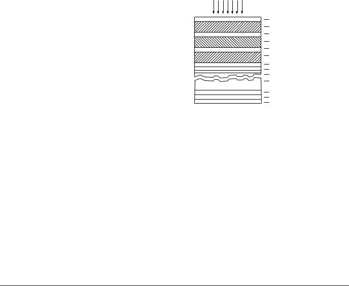
KODAK VISION Color Print Film / 2383, KODAK VISION Premier Color Print Film / 2393 and KODAK VISION Color Teleprint Film / 2395 / 3395 are multi-layer films with incorporated-color couplers. Figure 9-1, is a diagram of the film structure.
Figure 9-1
Cross Section of Unprocessed Color Print Films
EXPOSING LIGHT
Gel Protective Coat
Green-Sensitive Emulsion
Clear Gelatin Interlayer
Red-Sensitive Emulsion
Clear Gelatin Interlayer
Blue-Sensitive Emulsion
Anti-Halation Dye Layer
Stubbing Layer
U-Coat
Safety Film Base
4.7 Mil ESTAR Base
U-Coat
Conductive Anti-Static Layer
Scratch Resistant T-Coat W/Lube
This drawing illustrates only the relative layer arrangement of the film and is not drawn to scale.
F002_0252AC
The upper green-sensitive layer contains a colorless coupler that is converted to magenta dye during development, proportional to green-light exposure. The next emulsion layer is red-sensitive and contains a colorless coupler that forms a cyan dye, proportional to red exposure. The bottom emulsion layer is blue-sensitive, and contains a colorless coupler that forms a yellow dye, proportional to blue exposure.
The conductive anti-static layer and scratch resistant T-coat with lube are process surviving and retain their properties after processing.
KODAK VISION Color Print Films can be processed without a prebath and rem-jet removal and rinse, as indicated in Table 9-1. These films can be processed directly with the developer solution since they do not have a rem-jet backing to remove.
Process ECP-2E Specifications |
9-1 |

Process ECP-2E Steps
Table 9-1 Persulfate Bleach Sequence
Step |
Function |
|
|
1. Developer |
Reduces exposed silver halide grains in all three light-sensitive layers. The developing agent |
|
is oxidized by the exposed silver halide, and the oxidation product couples with the particular |
|
dye coupler incorporated within each layer to produce dye images. A silver image is formed |
|
simultaneously at the exposed silver-halide sites. |
|
|
2. Stop |
Stops the development of silver-halide grains and washes Color Developing Agent CD-2 |
|
from the film. |
|
|
NOTE: The film can now be handled in white light. |
|
|
|
3. Wash |
Removes excess acid stop. |
|
|
4. Accelerator |
Prepares the metallic silver present for the action of the persulfate bleach. |
|
|
5. Bleach (persulfate) |
Converts the metallic silver from both the sound track image and picture image that was |
|
formed during color development, to silver-halide compounds that can be removed by the |
|
fixer. In the sound track, the silver image formed during color development is converted to |
|
silver halide by the bleach. It is then redeveloped to a silver image by a black-and-white |
|
developer solution. |
|
|
6. Wash |
Removes residual bleach from the film, preventing contamination of the following solution. |
|
|
7. Fixer |
Converts the silver-halide compounds formed in the picture area during bleaching to soluble |
|
silver thiosulfate complex salts that are removed from the film in this fixer and subsequent |
|
wash. |
|
|
8. Wash |
Removes unused fixer and the residual soluble silver thiosulfate complex salts formed during |
|
fixing. |
|
|
9. Final Rinse |
Prepares the film for drying. |
|
|
10. Dryer |
Dries film for subsequent handling. |
|
|
11. Lubrication |
Promotes longer print projection life. It may be an inor off-line operation. See Module 2, |
|
Equipment and Procedures. |
|
|
If a customer wishes to retain the first fix and the first fix wash from Process ECP-2D, the sound application may still be skipped by threading the film directly from the bleach wash into the second fix.
Alternative Ferricyanide or UL Bleach Sequence
The steps and their functions are the same as in the recommended process, except the 20-second accelerator and 40-second persulfate bleach is replaced with a 60-second ferricyanide or UL bleach.
Safelights for Darkroom Illumination
When film is handled in a darkroom, whether printer room or processing room, safelights are used to provide enough light for working without fogging the film.
KODAK VISION Color Print Film / 2383, KODAK VISION Premier Color Print Film / 2393 and KODAK VISION Color Teleprint Film / 2395 / 3395 can be handled under illumination provided by standard safelight fixtures fitted with the KODAK No. 8 Safelight Filter / dark yellow. A sodiumvapor lamp fitted with KODAK WRATTEN Gelatin Filters No. 23A and 53 or 57, plus a neutral density filter to reduce the illumination intensity, can also be used. Conduct a careful safelight test before production work is started. The processing steps after the stop bath can be carried out in normal room light.
Film Storage and Handling
Ideally, processed film should be stored at 21°C (70°F) or lower, and 40 to 50 percent relative humidity for shortterm or active storage. For long-term storage conditions, store at 2°C (35°F) or lower at a relative humidity of 20 to 30 percent. In general, dye stability during long-term storage improves significantly with reduced temperature. See KODAK Publication No. H-23, The Book of Film Care, for more information.
Care must be exercised in the handling of print film to avoid scratches and/or dirt that will be noticeable on the projected print. Film handlers should use lint-free nylon or polyester gloves and handle the film by the edges as much as possible. Suggestions on film handling during processing are presented in Module 2, Equipment and Procedures.
Other Film Characteristics
For information on the physical characteristics of Kodak motion picture films (including edge identification, antihalation backing, perforations, and dimensional change characteristics), as well as cores, spools, winding, and packaging, refer to KODAK Publication No. H-1,
KODAK Motion Picture Film.
9-2 |
Process ECP-2E Specifications |
PROCESSING MACHINE DESIGN AND CONSTRUCTION
Machine Design
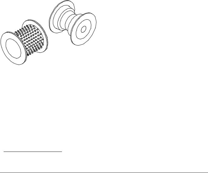
The films intended for Process ECP-2E are processed in roll form in a continuous processing machine. Film is transported through the various solution tanks, emulsion side out, on a series of spools. These spools are mounted in racks that fit into the tanks, and film is threaded over the spools so that it travels in a continuous spiral on each rack. The film should not be allowed to contact any part of the machine that can damage either the support or the emulsion side of the film. A soft rubber tire has been used successfully on flat spools to create a uniform film-support surface consisting of many soft, flexible fingers.* Such a soft-touch surface, which can be helpful in minimizing physical damage to the film, can be used on all rollers that contact the film base.
Rollers contacting the emulsion should be undercut as shown in Figure 9-2. Soft-touch tires can leave marks on the emulsion. Some machines use undercut rollers with sprockets to drive the film.
Figure 9-2
Soft-Touch Tire (Left) and Undercut Roller (Right)
The required treatment or solution time for each processing solution and wash is obtained by installing an appropriate number of racks in the various solutions and washes for a specific film transport speed. The size and number of racks are predetermined by the machine manufacturer. Some machine manufacturers build racks with the upper spools fixed and the lower spools mounted on a floater or slider. With such racks, solution times can be controlled by adjusting the positions of the floaters. To provide adequate agitation of the developer at the emulsion surface, the developer tank is equipped with a turbulator. A turbulator is a submerged series of tubes, having nozzles or drilled holes at various locations along the tubes, pointing toward the film strand. The turbulator can be an integral part of the machine rack. For more information on turbulator design, see Module 2, Equipment and Procedures.
The processor should be a conventional deep-tank machine. Submerged rollers and rack-drive assemblies are recommended for all solutions to minimize the splattering of solutions and aerial oxidation of the developer and fixer. Figure 9-3 is a schematic of a typical processing machine for Process ECP-2E using the recommended persulfate bleach. Figure 9-4 is a schematic of a typical processing machine for Process ECP-2E using the alternate ferricyanide or UL bleaches. Squeegees should be used at all the locations shown in the schematic to reduce contamination and minimize loss of solution by carry-over into subsequent solutions.
Eastman Kodak Company does not market processing machines or auxiliary equipment suitable for Process ECP-2E. However, a list of some manufacturers of processing equipment can be obtained through the Professional Motion Imaging offices.
F002_0254AC
* Described in A Soft-Touch Surface Designed for Scratch-Free MotionPicture Film Processing, Journal of the SMPTE, 79:712-715, August 1970.
Process ECP-2E Specifications |
9-3 |

Figure 9-3 Machine Schematic for Process ECP-2E with Persulfate Bleach Sequence
Light |
|
|
|
DRYER |
|
Normal Room |
|
|
10 |
FINAL |
RINSE |
|
|
|
60 |
WASH |
|
|
|
|
40 |
FIXER |
|
|
|
|
40 |
WASH |
|
|
EXHAUST |
SQUEEGEE |
20 40 |
PERSULFATE |
BLEACH BLEACH ACCELERATOR |
|
|
|
40 |
WASH |
|
Dark |
EXHAUST |
|
180 40 |
DEVELOPER STOP |
Solution times are in seconds. |
|
|
|
|
FILM FEED ON |
|
F002_1280EC
9-4 |
Process ECP-2E Specifications |

Figure 9-4 Machine Schematic for Process ECP-2E with Ferricyanide or “UL” Bleach Sequence
Light |
|
|
DRYER |
|
Normal Room |
|
10 |
FINAL RINSE |
|
|
|
60 |
WASH |
|
|
|
40 |
FIXER |
|
|
|
40 |
WASH |
|
|
SQUEEGEE |
60 |
FERRICYANIDE BLEACH |
or "UL" BLEACH |
|
|
40 |
WASH |
|
Dark |
EXHAUST |
180 40 |
DEVELOPER STOP |
Solution times are in seconds. |
|
|
|
FILM FEED ON |
|
F002_1281EC
Process ECP-2E Specifications |
9-5 |

Construction Materials
The construction materials recommended for the developer, stop, fixer, and bleach solutions are listed in Table 9-2. All the bleaches are quite corrosive. The UL bleach is slightly more corrosive than ferricyanide bleach, but less corrosive than persulfate bleach. Titanium, Hastelloy C, and engineering plastics such as PVC are, therefore, recommended materials for persulfate bleach. Use plastics compatible with low pH solutions (less than pH 5).
Red brass is commonly found in ferricyanide bleach systems, it will quickly be dissolved by persulfate bleach and UL bleach. In addition to machine tanks, it is often found in fittings, flowmeters, heat exchangers, and valves. Small redbrass parts have been found even when the bleach tank is constructed of titanium, Hastelloy C, or PVC.
The following materials are compatible with ferricyanide or “UL,” but not acceptable with persulfate bleach.
Monel is a commonly used staple material; it is dissolved by persulfate bleach in several hours. Stainless-steel staples are recommended for extended lifetime in persulfate bleach. Standard carbon-steel staples will show some corrosion, but maintain their integrity in persulfate bleach much longer than Monel-type staples. In all cases, it is a good practice to avoid extended exposure of staples to any bleach solution.
Some plastic and elastomeric materials will be degraded by persulfate bleach. This degradation is accelerated by the presence of chlorine in the bleach. Some materials known to be degraded by persulfate bleach are low-density polyethylene, acrylonitrile, butadiene, styrene, nylon 6/6, and neoprene. All plastics and elastomeric materials (other than PVC, RTV-60, silicone, and Vitron) should be tested before being used in persulfate bleach. Most plastics, including PVC, will discolor in persulfate bleach, but retain their mechanical properties. Tygon tubing, which turns white, is an example of this effect.
For best process control, equip the holding tank for the color developer replenisher with a tight-fitting floating cover. The cover will minimize air oxidation of the solution, and absorption of carbon dioxide from the air, which would change the pH. Clearance between the cover and the tank
wall should not be greater than 1⁄ inch (6.4 mm).
4
Polyethylene sheeting of 1⁄ inch (12.7 mm) thickness makes
2
adequate covers in sizes up to 3 feet (1 metre) in diameter. A dust cover alone permits air to come in contact with the solution and will allow some air oxidation to take place. Dust covers should be used for non-developer solution to minimize dirt in the replenisher tanks.
Additional information on materials construction and information on their use are given in The SPSE Handbook of Photographic Science and Engineering, Materials of Construction for Photographic Processing Equipment section. You may also contact the Kodak Information Center at 1-800-242-2424.
9-6 |
Process ECP-2E Specifications |

Table 9-2 Construction Materials for Process ECP-2E
|
Plastics |
|
|
Austenitic |
||
Solution |
(Polyvinyl |
|
|
|||
Titanium |
Hastelloy C |
Stainless Steel |
||||
Chloride or |
||||||
|
|
|
AISI Type 316 * |
|||
|
Polyolefins) |
|
|
|||
|
|
|
|
|
||
|
|
|
|
|
|
|
Bleach (Ferricyanide or “UL”): |
|
|
|
|
|
|
|
|
|
|
|
|
|
Tanks and Racks |
• † |
• |
• |
|
|
|
Mixing Tanks |
• † |
• |
• |
|
|
|
Replenisher Holding Tanks |
• † |
• |
• |
|
|
|
Piping, Pumps, Valves, and Filter Cores |
• † |
• |
• |
|
|
|
Overflow Holding Tank |
• † |
• |
• |
|
|
|
Bleach (Persulfate): |
|
|
|
|
|
|
|
|
|
|
|
|
|
Tanks and Racks |
• † |
• |
• |
|
|
|
Mixing Tanks |
• † |
• |
• |
• |
‡ |
|
Replenisher Holding Tanks |
• † |
• |
• |
|
|
|
Piping, Pumps, Valves, and Filter Cores |
• † |
• |
• |
|
|
|
Overflow Holding Tank |
• † |
• |
• |
|
|
|
Accelerator: |
|
|
|
|
|
|
|
|
|
|
|
|
|
Tanks and Racks |
• † |
• |
• |
|
• |
|
Mixing Tanks |
• † |
• |
• |
|
• |
|
Replenisher Holding Tanks |
• † |
• |
• |
|
• |
|
Piping, Pumps, Valves, and Filter Cores |
• † |
• |
• |
|
• |
|
Stop: |
|
|
|
|
|
|
|
|
|
|
|
|
|
Tanks and Racks |
• † |
• |
• |
|
|
|
Mixing Tanks |
• † |
• |
• |
• |
§ |
|
Replenisher Holding Tanks |
• † |
• |
• |
• § |
||
Piping, Pumps, Valves, and Filter Cores |
• † |
• |
• |
|
|
|
Others: |
|
|
|
|
|
|
|
|
|
|
|
|
|
Tanks and Racks |
• |
• |
• |
|
• |
|
|
|
|
|
|
|
|
Mixing Tanks |
• |
• |
• |
|
• |
|
|
|
|
|
|
|
|
Replenisher Holding Tanks |
• |
• |
• |
|
• |
|
|
|
|
|
|
|
|
Piping, Pumps, Valves, and Filter Cores |
• |
• |
• |
|
• |
|
|
|
|
|
|
|
|
*AISI Type 316 Stainless Steel has been extensively tested and is satisfactory for the uses listed in the table above. Refer to The SPSE Handbook of Photographic Science and Engineering, Materials of Construction for Photographic Processing Equipment Section for information on other Austenitic Stainless Steels.
†Plastics compatible with low pH solutions should be used (e.g., polyvinyl chloride, polypropylene, and high-density polyethyle ne). The compatibility of other plastics should be evaluated under actual use.
‡ Short-term storage of persulfate bleach in stainless steel tanks is acceptable.
§ Provided the concentration of sulfuric acid specified for the stop is not exceeded and fresh replenisher is always used.
Process ECP-2E Specifications |
9-7 |
Loading...