


 Loading...
KODAK PROFESSIONAL
HR 500 Film Scanner
P192_0016HC
Operator’s Guide
Part No. 6B6377
P015
© Eastman Kodak Company, 2000 - 2001
All rights reserved. Contents of this publication may not be reproduced in any form without permission from Eastman Kodak Company.

Unpacking Instructions for the
KODAK PROFESSIONAL
HR 500 Film Scanner
CAUTION: The HR 500 Film Scanner weighs almost 120 lbs (54,5 kg). Two people are needed to safely lift the scanner from the box.
Be sure the table for the scanner:
•is stable
•can support approximately 120 lbs (54,5 kg)
•is at least 30 in. (76,2 cm) long x 30 in. (76,2 cm) wide
1.Inspect the box to make sure there is no damage.
lid
styrofoam
scanner in  plastic bag
cutouts
styrofoam under scanner
front compartment with  accessories
If there is damage, contact the shipping company.
2.Remove the lid from the box.
3.Remove the scanner accessories (such as cables and SCSI board) from the front compartment of the box.
4.Compare the packing list to the actual contents. If there is an item missing:
•In the United States: call Eastman Kodak Company at 1-800-822-1414.
•Outside the United States: contact your local Kodak representative.
5.Open the plastic bag that covers the scanner and move the bag so you can reach the cutouts in the styrofoam under the scanner.
CAUTION: Two people are needed to lift the scanner from the box.
6.Use the styrofoam cutouts to reach under the scanner (one person in front; one person in the rear) and lift the scanner out of the box onto the table.
7.Keep the scanner packing material until you are satisfied that the scanner is operating satisfactorily.
CAUTION: Make sure the setting on the AC input module on the back of the scanner is compatible with the power source.
August 2001 |
iii |
iv |
August 2001 |

Regulatory Information
This equipment has been tested and found to comply with the limits for a Class A device, pursuant to part 15 of the FCC rules. These limits are designed to provide reasonable protection against harmful interference when the equipment is operated in a commercial environment. This equipment generates, uses, and can radiate radio frequency energy and, if not installed and used in accordance with the instruction manual, may cause harmful interference to radio communications. Operation of this equipment in a residential area is likely to cause interference; in which case, the user would be required to incur the expense of correcting the interference.
Cautionary Symbols
Hot Surface Symbol
CAUTION: Risk of burn. Wait at least 5 minutes for surface to cool.
Fuse Label
|
! |
|
|
(2) 100-120 V |
50/60 Hz |
6.3 A / 250 V / F |
|
|
|
|
(2) 200-240 V |
50/60 Hz |
3.15 A / 250 V / T |
|
|
|||||
|
|
|
|
|
|
|
CAUTION: Double pole / neutral fusing.
ATTENTION: Double pôle / fusible sur le neutre.
ACHTUNG: Zweipolige bzw. Neutralleiter - Sicherung!
CAUTION: The Kodak Professional HR 500 Film Scanner uses double pole/ neutral fusing.
August 2001 |
v |

Regulatory Information
Electrical Hazard Symbol
French:
Symbole de Danger É lectrique
German:
Elektrisches Gefahrensymbol
CAUTION: Risk of electrical shock. Test before touching.
French:
ATTENTION: Danger D’ É lectrocution. Vé rifier avant de toucher.
German:
VORSICHT: Gefahr von elektrischem Schlag. Vor Berü hrung prü fen.
Mechanical Hazard Symbol
French:
Symbole de Danger Mécanique
German:
Mechanisches Gefahrensymbol
CAUTION: Moving parts. Avoid contact.
French:
ATTENTION: Piè ces en mouvement. Ne pas toucher.
German:
VORSICHT: Bewegliche Teile. Nicht berü hren.
vi |
August 2001 |
Regulatory Information
Warranty Information
The following warranty information pertains to equipment that is installed in the United States only. For equipment installed in countries other than the United States, the terms and conditions of the new equipment warranty are provided by the Kodak company in the country in which the sale is finalized, or by a Kodakappointed distributor in those countries where Kodak does not have direct sales representation.
Warranty Period
Kodak warrants new equipment to function properly for 90 days from the date of initial installation. This warranty covers the purchaser of the equipment as well as anyone else who owns it during the warranty period.
Warranty Repair Coverage
If this equipment does not function properly during the warranty period, a Service and Support Field Engineer from Kodak will repair the equipment without charge during Kodak’s normal working hours (usually 8:00 a.m. to 5:00 p.m., Monday through Friday). Such repair service will include any adjustments and/or replacement of parts required to maintain your equipment in good working order. Supply items are billed as required.
How to Obtain Service
Before you call, please know your scanner’s K-Number. The K-Number label is attached to the front of the scanner chassis near the filter and lamp; lift the lamp- and-filter-access door to see the K-number (see Front View on page 1-4).
For service and support:
•In the United States: call Eastman Kodak Company at 1-800-822-1414.
•Outside the United States: contact your local Kodak representative.
August 2001 |
vii |
Regulatory Information
Limitations
Warranty service is limited to areas within Kodak’s established marketing centers in the contiguous United States, the island of Oahu in Hawaii, and some areas of Alaska.
This warranty does not cover circumstances beyond Kodak’s control; it does not cover service or parts for any attachments, accessories, or alterations not marketed by Kodak, nor to correct problems resulting from their use.
Damage caused by failure to meet the electrical specification in this manual is not covered under the warranty to service agreement claim.
Kodak makes no other warranties, express, implied, or of merchantability, for this equipment.
Repair or replacement without charge is Kodak’s only obligation under this warranty. Kodak will not be responsible for any consequential or incidental damages resulting from the sale, use, or improper functioning of this equipment, even if loss or damage is caused by the negligence or the fault of Kodak.
Such damages, for which Kodak is not responsible, include, but are not limited to, loss of revenue or profit, downtime costs, loss of use of the equipment, cost of any substitute equipment, and facilities or services of claims of your customers for such damages.
This limitation of liability does not apply to claims for injury to persons or damage to property caused by the sole negligence or fault of Kodak or by persons under its direction or control.
Kodak Service Agreements
For information on Kodak service agreements:
In the United States: call Kodak’s Service Marketing Contract Administration and Billing Support at 1-800-645-6325.
Outside the United States: contact your local Kodak representative.
viii |
August 2001 |
Contents
|
Regulatory Information........................................................................................................................... |
v |
|
Cautionary Symbols ........................................................................................................................ |
v |
|
Warranty Information ..................................................................................................................... |
vii |
|
About This Guide .................................................................................................................................. |
xi |
|
Using This Guide ............................................................................................................................ |
xi |
1 |
Introduction and Overview .................................................................................................................. |
1-1 |
|
Product Description ...................................................................................................................... |
1-1 |
|
Features and Benefits .................................................................................................................. |
1-2 |
|
Before You Begin ......................................................................................................................... |
1-3 |
|
Equipment Overview .................................................................................................................... |
1-4 |
|
Recommended Configuration of the Host Computer.................................................................... |
1-5 |
|
Film Sizes ..................................................................................................................................... |
1-6 |
2 Connecting and Operating the Scanner.............................................................................................. |
2-1 |
|
|
Preparing the Host Computer....................................................................................................... |
2-1 |
|
Connecting the Scanner ............................................................................................................... |
2-2 |
|
Starting Up the Scanner System .................................................................................................. |
2-6 |
|
Operating the Scanner ................................................................................................................. |
2-8 |
|
Shutting Down the Scanner........................................................................................................ |
2-13 |
3 |
Validating the Scanner ........................................................................................................................ |
3-1 |
|
Starting the SAM Software ........................................................................................................... |
3-1 |
|
Setting the Magnification .............................................................................................................. |
3-3 |
|
Calibrating the Scanner ................................................................................................................ |
3-4 |
|
Making a Test Scan...................................................................................................................... |
3-5 |
|
Autofocusing................................................................................................................................. |
3-7 |
|
Scanning the Image...................................................................................................................... |
3-8 |
|
Checking the Scan ....................................................................................................................... |
3-8 |
4 |
Maintaining the Equipment.................................................................................................................. |
4-1 |
|
Cleaning Procedures .................................................................................................................... |
4-1 |
|
Replacement Procedures ............................................................................................................. |
4-4 |
Appendix A: Using the Service and Assembly Module (SAM)............................................................... |
A-1 |
|
|
Installing the Service and Assembly Module (SAM) Software..................................................... |
A-2 |
|
Using the Operations Controls .................................................................................................... |
A-3 |
Appendix B: Ordering Accessories and Supplies .................................................................................. |
B-1 |
|
|
Accessories ................................................................................................................................. |
B-1 |
|
Supplies....................................................................................................................................... |
B-2 |
Appendix C: Scanner Specifications...................................................................................................... |
C-1 |
|
August 2001 |
ix |
Contents |
|
Appendix D: Using the Long Roll Accessory ......................................................................................... |
D-1 |
Installing the Software for the Long Roll Accessory .................................................................... |
D-2 |
Installing or Removing the Long Roll Accessory ......................................................................... |
D-5 |
Punch Sensors .......................................................................................................................... |
D-14 |
Setting the Punch Reader Height for the Current Film Size ...................................................... |
D-14 |
Appendix D-1: Calibrating the Sensor Offsets........................................................................... |
D-24 |
Appendix D-2: Determining and Setting the Trigger Points....................................................... |
D-34 |
Appendix D-3: Maintenance ...................................................................................................... |
D-38 |
Appendix D-4: Initial Setup of Sensors...................................................................................... |
D-42 |
Appendix D-5: Table of Scan Area Values ................................................................................ |
D-45 |
Appendix D-6: Film Splicing and Editing Guidelines ................................................................. |
D-46 |
x |
August 2001 |
About This Guide
This Operator’s Guide for the KODAK PROFESSIONAL HR 500 Film Scanner includes procedures for operating, maintaining, and troubleshooting the scanner. It also includes an appendix for the optional Long Roll Accessory.
This guide is intended for personnel who operate the scanner. It assumes you have a basic knowledge of computer operations and film scanners.
Using This Guide
The guide is organized as follows:
Chapter 1 Introduction—product description, features and benefits, equipment overview, and recommended configuration
Chapter 2 Connecting and Operating the Scanner—connecting the Kodak Professional HR 500 Film Scanner to the host computer, starting up the scanner, preparing to scan an image, performing a scan and shutting down the scanner
Chapter 3 Validating the Scanner—instructions for using the Service and Assembly Module (SAM) and Adobe PhotoShop software to validate that the scanner functions properly
Chapter 4 Maintaining the Equipment—procedures to be done by the person in your lab who is responsible for maintenance of the scanner
Appendix A Using the Service and Assembly Module (SAM)—an overview of using SAM for validating the scanner and for other user functions
Appendix B Ordering Accessories and Supplies—includes descriptions and order numbers for scanner accessories and supplies
Appendix C Scanner Specifications—includes space, electrical, and environmental requirements for the scanner
Appendix D Using the Long Roll Accessory—instructions for installing and using the (optional) Long Roll Accessory with the scanner
August 2001 |
xi |
About This Guide
xii |
August 2001 |
1 Introduction and Overview
This chapter includes:
•product description
•features and benefits
•equipment overview
•recommended configuration for host computer
•film sizes
Product Description
The Kodak Professional HR 500 Film Scanner is designed to quickly generate high-resolution digital images from photographic negatives and positives.
The scanner accepts films ranging from 35 mm to 70 mm widths, including 46 mm width film and the 120 series formats, with up to 90 mm frame lengths.
The scanner digitally captures images and stores them in files up to 128 MB (format dependent) in size. The scanner is capable of variable magnifications from 0.5 to 2.0.
How the Scanner Works
The image on the film is focused onto a Charged Coupled Device (CCD) that has three parallel linear rows of light-sensitive elements, one row for each color. Each of these lines is exposed to a corresponding line of image on the film. The time to expose each line properly is controlled electronically and is a function of the:
•sensitivity of the CCD
•amount and spectral distribution of light from the light source
•lens aperture
•magnification factor
August 2001 |
1-1 |
Introduction and Overview
After the exposure, the data from the photosensitive sites on the CCD is transferred to readout registers for each line, where it is then shifted out and digitized one pixel at a time. While the data is shifted out, the next set of lines is exposed.
The film is moved to expose a new line of the image for each set of lines read from the CCD. This motion is precisely controlled to ensure that the aspect ratio of the image is not changed and that the colors align correctly when the data is recombined to correct for the distance between the sensor rows.
Features and Benefits
Features and benefits of the HR 500 Film Scanner include:
•high speed and high image quality digital capture
•handling of cut negatives, mounted slides, strips, short rolls, and long roll lengths up to 200 feet (61 meters)
•compatibility with familiar software, such as
–Kodak Professional Digital Print Production Software (DP2)
–Kodak Professional HR 500 TWAIN Data Source, which can be used with any TWAIN-compliant program
•compatibility with familiar hardware, such as Kodak Professional Digital Multiprinters and Kodak Professional LED Printers
1-2 |
August 2001 |
Introduction and Overview
Before You Begin
It is important that you know when to calibrate and when to focus the scanner. The table below is a guideline for calibrating and focusing. Focusing can occur as infrequently as when a different film format is scanned or as frequently as every scan.
Action or Condition |
Need to |
Need to |
|
Calibrate? |
Focus? |
||
|
|||
|
|
|
|
Changing the magnification |
Yes |
Yes |
|
|
|
|
|
Replacing the lamp |
Yes |
No |
|
|
|
|
|
Changing the balance filter position from negative |
Yes |
Yes |
|
to positive or from positive to negative |
|
|
|
|
|
|
|
The scanner has not been calibrated at least twice |
Yes |
No |
|
during the first half of a production shift |
|
|
|
|
|
|
|
Cleaning the light bar |
Yes |
No |
|
|
|
|
|
Replacing the balance filters or the IR filter |
Yes |
No |
|
|
|
|
|
Changing the film holder without changing the |
Yes |
Operator |
|
magnification |
|
Preference |
|
|
|
|
|
Scanning slides |
No |
Operator |
|
|
|
Preference |
|
|
|
|
|
Changing from scanning a long roll to scanning a |
Yes |
Yes |
|
cut negative |
|
|
|
|
|
|
You can manipulate scanned images using a program such as the Kodak
Professional Digital Print Production Software (DP2) or the Kodak Professional
HR 500 TWAIN Data Source before sending the images to your digital printer.
August 2001 |
1-3 |

Introduction and Overview
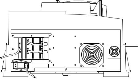
Equipment Overview
Front View
K-number is visible when this door is open
P192_0016HC
Rear View
Serial
Number XXX
power switch |
latch release |
dataplate includes |
screw |
serial number |
P192_0019HC
1-4 |
August 2001 |
Introduction and Overview
Recommended Configuration of the Host Computer
The scanner is designed to communicate with Windows NT and Windows 2000 platforms with the following configuration.
IMPORTANT: To ensure proper operation of the scanner, use the Ultra-Wide
SCSI board provided with the scanner.
Built-in SCSI interfaces in some computers may interfere with the provided Ultra-Wide SCSI board.
Minimum Host Computer Hardware Requirements
•Dual Pentium III/600 MHz
•512 MB memory
•10 GB available disk space
•Dedicated SCSI host adapter (provided with scanner)
NOTES: The hardware configuration is a minimum; for higher performance, a high speed and larger memory capacity machine is required.
The SCSI board must be dedicated to running only the HR 500 Film
Scanner.
A SCSI cable connects the host computer to the scanner. This interface enables the transfer of digital image data from the scanner to the host computer.
Minimum Software Requirements
•Windows NT 4.0, Service Pack 6 for using the scanner and software
•Adobe Photoshop 5.5 or higher for validating operation of the scanner
August 2001 |
1-5 |
Introduction and Overview
Film Sizes
Commonly available color negative, color reversal (positive), and black-and-white films are supported by the scanner.
The scanner accepts these film sizes:
•35 mm
–standard perforated format
–un-perforated, up to 60 mm frame length
•46 mm, up to 90 mm frame length
•120/220 (62 mm)
–6 x 4.5 cm
–6 x 6 cm
–6 x 7 cm
–6 x 8 cm
–6 x 9 cm
•70 mm
–split 70 mm
–full 70 mm
Film Holders Provided with the Scanner
Cut-gate film holders for these film sizes are provided with the scanner:
•35 mm double-perforated
•35 mm mounted slides
•70 mm-CAL
•6 x 4.5 cm vertical
•6 x 4.5 cm horizontal
•6 x 6 cm
•6 x 7 cm
•6 x 9 cm
1-6 |
August 2001 |
2 Connecting and Operating the Scanner
This chapter gives instructions for:
•preparing the host computer
•connecting the Kodak Professional HR 500 Film Scanner to the host computer
•starting up the scanner system
•preparing to scan an image
•performing a scan
•shutting down the scanner
Preparing the Host Computer
CAUTION: Do not connect power to the scanner.
1.Install the Ultra-Wide SCSI board into the host computer.
IMPORTANT: Check the README file for your operating system before you install the software.
2.Install the SAM software. See Installing the Service and Assembly Module (SAM) Software on page A-2.
August 2001 |
2-1 |
Connecting and Operating the Scanner
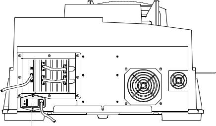
Connecting the Scanner
CAUTION: Make sure the setting on the AC input module on the back of the scanner agrees with the power source.
AC input module
P192_0019HC
The AC input module is factory-set to 115 V AC (60 Hz) as labeled. The accessories shipped with your scanner include two 220 V fuses (3.15 amps) to convert the scanner to 220 V operation.
If your power source is 220 or 230 V AC, verify the configuration of the AC input module. In some regions, the setting and the fuses may have been changed for you. If not, follow the procedure for Changing the AC Input Voltage Setting and the Fuses.
Remove the voltage sticker from the AC input module.
2-2 |
August 2001 |
Connecting and Operating the Scanner
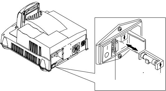
Changing the AC Input Voltage Setting and the
Fuses
If needed, change the AC input voltage setting (voltage selector switch) and both fuses from 115 V AC to 220 V AC operation:
1. Make sure the power cord is removed from the scanner.
locking tab
115V
voltage selector switch
2.Insert a straight-blade screwdriver into the locking tab to open the AC input module.
3.Using your fingers (or, if needed, needle-nose pliers), remove the voltage selector switch.
4.Orient the voltage selector switch with 220 V AC facing you and insert it into the AC input module.
August 2001 |
2-3 |
Connecting and Operating the Scanner
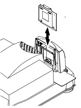
5.Remove the two 115 V AC (6.3 amp) fuses and replace them with the 220 V AC (3.15 amp) fuses. Make sure the arrows are pointing up.
115V
fuse arrow
fuse in holder
6. Close the AC input module.
2-4 |
August 2001 |
Connecting and Operating the Scanner
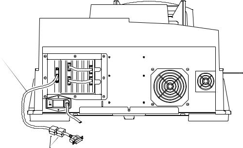
Attaching the Cables
CAUTION: In the next step, avoid forcing the cable pins when plugging the cable into the scanner. You need a straight-blade screwdriver to complete the attachment of the cable to the scanner.
1.Attach the Ultra-Wide SCSI cable to the scanner and to the host computer. The host end of the cable contains ferrite beads.
2.Attach the power cable from the scanner to the power source.
SCSI cable
power cable
P192_0100HC
ferrite beads
August 2001 |
2-5 |
Connecting and Operating the Scanner
Starting Up the Scanner System
NOTE: If the scanner’s power has been on and the scanner has been calibrated, continue with Operating the Scanner beginning on page 2-8.
IMPORTANT: Before operating the scanner in a production environment for the first time, validate that the scanner is working properly. See Chapter 3, Validating the Scanner.
Placing the Empty Film Holder in the Film Holder
Guide
The empty “70MM-CAL” film holder must be in place in the film holder guide when you power up the scanner.
edge of handle facing back of scanner
LAC-M
M07
 70MM-CAL film holder
film holder guide
P192_0020GC
1.With the edge of the top handle facing the back of the scanner, center the film holder between the two rails of the film holder guide.
2.Lower the film holder and let it gently fall into place in the scanner.
3.With your finger, apply pressure to the handle to make sure the film holder is fully seated.
2-6 |
August 2001 |
Connecting and Operating the Scanner
Powering up the Scanner and the Host Computer
1.Turn on the scanner’s power switch.
NOTE: The green LED light on the scanner indicates only that AC power is supplied to the scanner, not that the system is ready.
Three sets of beeps will sound (first set: one beep; second set: two short beeps; third set: two short, then one long beep).
As a visual indicator that the scanner is ready, the scanner lamp lights and remains lit.
2.Turn on power to the host computer and wait until the computer desktop appears.
3.Wait 10 minutes for the lamp to warm up.
power 
switchP192_0019HC
August 2001 |
2-7 |
Connecting and Operating the Scanner
Operating the Scanner
Setting the Magnification and Calibrating the
Scanner
Use your host computer’s scanner software to do this procedure.
NOTE: The terminology used in your scanner software may differ from that used in this document. Refer to the software manual’s instructions for performing specific operations such as calibrating the scanner and setting the magnification.
With the empty 70MM-CAL film holder in place in the scanner:
1.Set the magnification to the desired level.
2.Calibrate the scanner.
Setting the Scan Parameters
Using the software installed on your host computer, set the scan parameters, such as the area to be scanned and the file that will contain the scanned image.
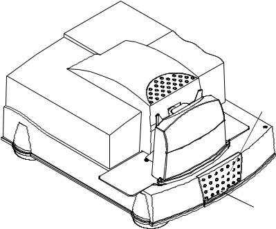
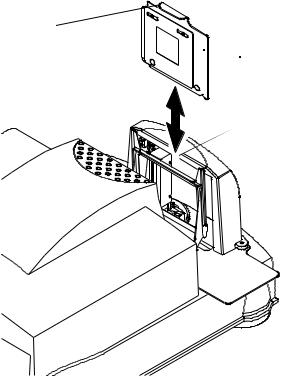
Selecting the Negative or Positive Balancing Filter
lamp-and-filter- access door
lift door open from  here
here
P192_0016HC
1. Lift open the lamp-and-filter-access door.
2-8 |
August 2001 |
Connecting and Operating the Scanner
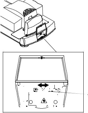
2.Make sure the red handle is in the correct position— either negative or positive— for scanning a negative or a mounted slide (positive).
IMPORTANT: If you changed the setting of the balance filter, you must calibrate the scanner before continuing. See Setting the Magnification and Calibrating the Scanner on page 2-8.
|
|
|
|
|
|
|
|
|
|
|
|
|
|
|
|
|
|
|
|
|
|
|
|
|
|
|
|
|
|
|
|
|
|
|
|
|
|
|
|
|
|
|
|
|
|
|
|
|
|
|
|
|
|
|
|
|
|
|
|
|
|
|
|
|
|
|
|
|
|
|
|
|
|
POS |
|
|
|
|
|
|
|
|
|
|
NEG |
|
|
|
|
|
|
|||||||
|
|
|
|
|
|
|
|
|
|
|
|
|
|
|
|
|
|
|
|
|
|
|
|
|
|
|
|
|
|
|
|
|
|
|
|
|
|
|
|
|
|
|
|
|
|
|
|
|
|
|
|
|
|
|
|
|
|
|
|
|
|
|
|
|
|
|
|
|
|
|
|
|
|
|
|
|
|
|
|
|
|
|
|
|
|
|
|
|
|
|
|
|
|
|
|
|
|
|
red handle is in NEG position
August 2001 |
2-9 |
Connecting and Operating the Scanner
Inserting a Negative or Mounted Slide in the
Scanner
Select the appropriate film holder for the negative or mounted slide you will be scanning.
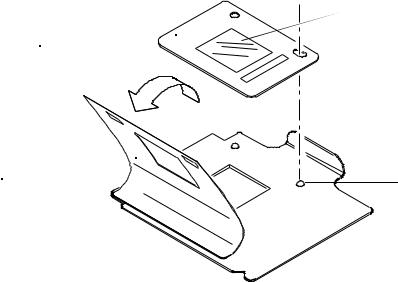
Preparing a Carded Negative
IMPORTANT: For best focus, use the film holder that is closest to the size of the opening in the aperture card.
1.Lift the film holder’s magnetic sheet.
2.With the emulsion side toward the rear of the scanner, locate the carded negative on the film holder’s two pins.
3.Carefully close the magnetic sheet over the carded negative.
emulsion  side
side
carded negative
magnetic |
|
sheet |
pin |
 film holder
P192_0021AC
Continue with Placing the Film Holder in the Scanner on page 2-12.
2-10 |
August 2001 |
Connecting and Operating the Scanner
Preparing an Uncarded Negative
Wear clean, cotton gloves when handling the negative. Illuminate the negative with a light box or hold the negative up to the light to view and align the negative.
1.Identify the emulsion side of the negative.
The emulsion side is the dull side of the negative. The printing appears backwards.
2.Select either landscape or portrait orientation.
3.Lift the magnetic sheet.
4.With the emulsion side toward the rear of the scanner, carefully align the negative over the rectangular opening in the film holder.
5.Close the magnetic sheet over the negative.
Continue with Placing the Film Holder in the Scanner on page 2-12.
Preparing a Mounted Slide
1.With the emulsion side toward the rear of the scanner, align the mounted slide on the film holder between the pins.
2.Carefully insert the mounted slide under the film holder’s clamps and into place, keeping the slide aligned.
August 2001 |
2-11 |
Connecting and Operating the Scanner
Placing the Film Holder in the Scanner
1.Hold the film holder guide so the top handle faces the back of the scanner. Center the film holder between the two rails of the film holder guide.
2.Lower the film holder and let it gently fall into place in the scanner.
3.With your finger, apply pressure to the handle to make sure the film holder is fully seated.
edge of handle facing back of scanner 
 film holder
film holder guide
P192_0020GC
2-12 |
August 2001 |
Loading...