


Kodak
SERVICE MANUAL
for the
Publication No. SM 2547-1
03/98
KODAK EKTAPRO Slide Projector
Model 4020, 5020, 7020, 9020, (9020/CINE)
Model 9020
© Kodak AG, Stuttgart 1998
Kodak AG, Stuttgart |
I |
03/98 |

Service Manual |
SM 2547-1 |
PLEASE NOTE
The information contained herein is based on the experience and knowledge relating to the subject matter gained by Kodak prior to publication. No patent license is granted by this information. Kodak reserves the right to change this information without notice, and makes no warranty, express or implied, with respect to this information. Kodak shall not be liable for any loss or damage, including consequential or special damages, resulting from the use of this information, even if loss or damage is caused by Kodak’s negligence or other fault.
03/98 |
II |
Kodak AG, Stuttgart |
SM 2547-1 |
Service Manual |
TABLE OF CONTENTS
ELECTROSTATIC DISCHARGE ......................................................................................................... |
1-1 |
Overview..................................................................................................................................... |
1-1 |
Awareness .................................................................................................................................. |
1-1 |
Action ......................................................................................................................................... |
1-1 |
Every Day ................................................................................................................................... |
1-2 |
During Maintenance and Repair ................................................................................................. |
1-2 |
1. GENERAL INFORMATION .............................................................................................................. |
1-3 |
Service Tools ...................................................................................................................................... |
1-3 |
For Models 4020/5020/7020/9020 and 9020/CINE ............................................................................ |
1-3 |
Safety Precaution................................................................................................................................ |
1-4 |
Safety Check ...................................................................................................................................... |
1-5 |
2. INTRODUCTION .............................................................................................................................. |
2-1 |
Projector Models ................................................................................................................................. |
2-2 |
EKTAPRO Model 4020............................................................................................................... |
2-2 |
Features and Functions: ............................................................................................................. |
2-2 |
EKTAPRO Model 4020............................................................................................................... |
2-3 |
EKTAPRO Model 5020............................................................................................................... |
2-4 |
Features and Functions: ............................................................................................................. |
2-4 |
EKTAPRO Model 7020............................................................................................................... |
2-5 |
Features and Functions: ............................................................................................................. |
2-5 |
EKTAPRO Model 9020............................................................................................................... |
2-6 |
Features and Functions: ............................................................................................................. |
2-6 |
Overview .................................................................................................................................... |
2-7 |
Accessories......................................................................................................................................... |
2-8 |
DUAL LAMP MODULE............................................................................................................... |
2-8 |
CABLE REMOTE ....................................................................................................................... |
2-8 |
Kodak AG, Stuttgart |
III |
03/98 |
Service Manual |
SM 2547-1 |
CONDENSER KIT 4X4 (with CLIP)............................................................................................ |
2-9 |
IR REMOTE System RA/LP (Laser Pointer) ............................................................................ |
2-10 |
12/7-PIN MODULE ................................................................................................................... |
2-10 |
LENS SUPPORT...................................................................................................................... |
2-10 |
12/7-PIN ADAPTER CABLE..................................................................................................... |
2-11 |
TWIN SOCKET ADAPTER....................................................................................................... |
2-11 |
SLIDE SYNCHRONIZER ......................................................................................................... |
2-12 |
LAMPS ..................................................................................................................................... |
2-12 |
Specification...................................................................................................................................... |
2-13 |
CONNECTORS ................................................................................................................................ |
2-13 |
Remote SOCKET on Projector:................................................................................................ |
2-13 |
P-Bus / RS 232 “IN”................................................................................................................ .. |
2-14 |
P-Bus / RS 232 “OUT”............................................................................................................. |
2- 14 |
ACCESSORY SLOT................................................................................................................. |
2-15 |
OEM ACCESSORIES ........................................................................................................................ |
2-16 |
COPYWRITE............................................................................................................................ |
2-16 |
SLIDE SYNCHRONIZER ADAPTER by KODAK AUSTRALIA................................................ |
2-17 |
ADAPTER by MÜWO ............................................................................................................... |
2-1 8 |
ADAPTERS by MAYER & ZELLER.......................................................................................... |
2-19 |
ADDRESSES ..................................................................................................................................... |
2-20 |
CONTROL SYSTEMS.............................................................................................................. |
2-20 |
SOFTWARE for direct PC CONTROL...................................................................................... |
2-21 |
RACKS ..................................................................................................................................... |
2-21 |
EXTERNAL TIMER .................................................................................................................. |
2-21 |
3. THEORY GUIDE .............................................................................................................................. |
3-1 |
Block Diagram..................................................................................................................................... |
3-1 |
Microcontroller Unit ............................................................................................................................. |
3-3 |
Description of Functions ..................................................................................................................... |
3-4 |
03/98 |
IV |
Kodak AG, Stuttgart |
SM 2547-1 |
Service Manual |
Power Supply ............................................................................................................................. |
3-4 |
The TRANSFORMER supplies the following voltages: .............................................................. |
3-4 |
The POWER REGULATION PCB contains:............................................................................... |
3-4 |
The output voltages and signal are:............................................................................................ |
3-4 |
Switch On / Initialize Procedure.................................................................................................. |
3-6 |
Slide Change Sequence ............................................................................................................. |
3-7 |
Tray Motion................................................................................................................................. |
3-8 |
Tray Motion Sequence: .............................................................................................................. |
3-9 |
LAMP Control ........................................................................................................................... |
3-11 |
a) Dual LAMP Operation .......................................................................................................... |
3-11 |
b) Low/High LAMP Setting ....................................................................................................... |
3-12 |
c) LAMP Protection................................................................................................................... |
3-12 |
d) LAMP Voltage Control.......................................................................................................... |
3-12 |
e) Lamp Dimming ..................................................................................................................... |
3-13 |
Focus ........................................................................................................................................ |
3-15 |
Auto focus................................................................................................................................. |
3-16 |
P-BUS ..................................................................................................................................... |
3-17 |
Command Structure ................................................................................................................. |
3-18 |
Accessory slot .......................................................................................................................... |
3-19 |
Remote Control ........................................................................................................................ |
3-20 |
4. DISASSEMBLY/ASSEMBLY........................................................................................................... |
4-1 |
UPPER HOUSING.............................................................................................................................. |
4-1 |
BUTTONS and COVER PLATES ....................................................................................................... |
4-2 |
Assembly .................................................................................................................................... |
4-3 |
CENTER HOUSING ........................................................................................................................... |
4-4 |
FAN, KEYBOARD PCB and TRAY MOTION PCB............................................................................. |
4-8 |
BACK PANEL PCB........................................................................................................................... |
4-10 |
TRANSFORMER, POWER SUPPLY PCB and BACK PLATE ASSEMBLY .................................... |
4-11 |
Kodak AG, Stuttgart |
V |
03/98 |
Service Manual |
SM 2547-1 |
MECHANISM FRAME and LENS MOUNT....................................................................................... |
4-12 |
LENS MOUNT .................................................................................................................................. |
4-13 |
Model 4020/7020 ...................................................................................................................... |
4-15 |
RETAINER AF ASSEMBLY.............................................................................................................. |
4-16 |
Model 5020/9020 and 9020/CINE ............................................................................................ |
4-16 |
MECHANISM FRAME ...................................................................................................................... |
4-18 |
AUTO FOCUS PCB and FOCUS MOTOR....................................................................................... |
4-21 |
Master Board PCB ............................................................................................................................ |
4-22 |
Master Board PCB Connectors ................................................................................................ |
4-23 |
MICROCONTROLLER ............................................................................................................. |
4-24 |
LOWER HOUSING........................................................................................................................... |
4-25 |
DUAL LAMP MODULE ..................................................................................................................... |
4-26 |
DUAL LAMP MODULE............................................................................................................. |
4-29 |
Lubrication ........................................................................................................................................ |
4-30 |
5. DIAGNOSTICS ................................................................................................................................. |
5-1 |
Diagnostic Overview EKTAPRO 4020/5020/7020/9020 and 9020/CINE ........................................... |
5-1 |
Preparation ......................................................................................................................................... |
5-3 |
Conditions:.................................................................................................................................. |
5-3 |
No Function......................................................................................................................................... |
5-4 |
Switch on Procedure Problems........................................................................................................... |
5-9 |
Lamp Problems EP 4020/5020/7020/9020 and 9020/CINE ............................................................. |
5-12 |
Mirror Position................................................................................................................................... |
5-17 |
Brightness Test......................................................................................................................... |
5-17 |
Switch On Procedure ........................................................................................................................ |
5-18 |
Switch On Procedure complete - No Keyboard Function ................................................................. |
5-19 |
No function with REMOTE CONTROL ............................................................................................. |
5-20 |
IR Remote Control.................................................................................................................... |
5-20 |
Cable Remote ................................................................................................................................... |
5-23 |
03/98 |
VI |
Kodak AG, Stuttgart |
SM 2547-1 |
Service Manual |
No Slide Transport forward/reverse and other projection problems ................................................. |
5-24 |
Shutter Problems .............................................................................................................................. |
5-35 |
Fan Problems.................................................................................................................................... |
5-27 |
Slide Obstruction in Slide Tray.......................................................................................................... |
5-29 |
Conditions for a correct transport cycle .................................................................................... |
5-29 |
Wrong Transport Step by 80/140 SLIDE TRAY................................................................................ |
5-30 |
No Focus Actuation........................................................................................................................... |
5-32 |
No Standby Function ........................................................................................................................ |
5-33 |
Communication Trouble 4010/5010/9010......................................................................................... |
5-35 |
AUTO FOCUS 5020/9020 and 9020/CINE: No AUTO FOCUS Function......................................... |
5-39 |
Accessory Slot 7020/9020 ................................................................................................................ |
5-40 |
Malfunction of the 12/7 PIN Module.......................................................................................... |
5-40 |
6. Projector Checking ......................................................................................................................... |
6-1 |
Slide Transport Problems ................................................................................................................... |
6-1 |
Slide jam (all models) ................................................................................................................. |
6-2 |
CODER DISK ..................................................................................................................................... |
6-2 |
7. MAINTENANCE ............................................................................................................................... |
7-1 |
Maintenance Intervals......................................................................................................................... |
7-1 |
Maintenance Procedure...................................................................................................................... |
7-1 |
Cleaning.............................................................................................................................................. |
7-1 |
Ultrasonic cleaning ..................................................................................................................... |
7-2 |
Lubrication .......................................................................................................................................... |
7-3 |
Kodak AG, Stuttgart |
VII |
03/98 |
Service Manual |
SM 2547-1 |
blank page |
|
03/98 |
VIII |
Kodak AG, Stuttgart |

SM 2547-1 |
Service Manual |
ELECTROSTATIC DISCHARGE
CAUTION
This equipment includes parts and assemblies sensitive to damage from electrostatic discharge. Use caution
to prevent damage during all service procedures.
Overview
Electrostatic discharge (ESD) is a primary source of
-product downtime
-lost productivity
-costly repair.
While we cannot feel a static charge of less than 3,500 volts, as few as 30 volts can damage or destroy essential components in the electronic equipment. As technology advances, these components will be even more vulnerable to ESD destruction.
Therefore, to maintain and increase productivity and profitability, you must observe ESD guidelines.
Effective ESD control requires the following things.
Awareness
Everyone in your organization should be aware of ESD because partial ESD control is no ESD control at all. Everyone needs to remember that:
-ESD is a primary source of equipment failures and intermittent malfunctions.
-ESD affects productivity and profitability.
-ESD can be controlled.
Action
Everyone from senior management to the evening security crew, must observe ESD guidelines.
-If you repair and maintain electronic equipment, always wear grounding straps and work at ESD protected sites.
-If you work around electronic equipment, keep static generators like plastic trash bags away from sensitive components.
-Observe ESD guidelines everyday. (See the following sections for special tips).
-Remember, effective ESD control is everyone’s responsibility:
Kodak AG, Stuttgart |
1-1 |
03/98 |
Service Manual |
SM 2547-1 |
Every Day
1. Keep trash away from static-sensitive equipment. Plastic materials, such as trash can liners and plastic foam cups, generate the static electricity that damages or destroys electronic components.
2. Look at the label. Static-sensitive components are marked with bright graphic labels. Follow the label directions.
3. Spray the carpet. ESD that is generated when you walk over carpet is a major cause of component destruction. In some cases, especially in low-humidity environments, you may need to periodically spray carpets with an anti-static spray that is available at local stores.
During Maintenance and Repair
1. Wear a grounding strap when you work with static-sensitive components. Always make certain that the clip is attached to a properly grounded, unpainted surface.
2. Use a portable grounding mat if you cannot repair components at an ESD-protected workstation. (Kodak’s Customer Equipment Services Division can help you in set up ESD-protected workstations.)
3 . Use protective packaging when you transport components from one area to another. Transparent antistatic bags, available from a variety of manufacturers, shield the components from further damage.
03/98 |
1-2 |
Kodak AG, Stuttgart |
SM 2547-1 |
Service Manual |
1. GENERAL INFORMATION
Service Tools
Use the following tools to repair a KODAK EKTAPRO Slide Projector:
TORX Screw Driver size 206
TORX Screw Driver size 210
TORX Screw Driver size 215 or TORX bits TL-3255
TORX Screw Driver size 220
Logic Probe |
TTL/CMOS |
|
|
Oscilloscope |
- only for checks on the AUTO FOCUS PCB. |
||
Digital Multimeter |
|
Voltage |
5 to 240 V AC |
|
|
|
0 to 50 V DC |
|
|
Current |
1 to 100 mA DC Accuracy: 1% |
|
|
|
0,1 to 2 A DC |
|
|
|
0,1 to 5 A AC |
|
|
|
The multimeter should have RMS capability |
|
|
Accuracy |
1% |
Fixture Tool |
|
622 0454 |
|
For Models 4020/5020/7020/9020/9020/CINE |
|||
PLCC Extractor Tool |
TL-4430 |
|
|
Service Computer |
100% IBM compatible |
||
|
|
Hard disk |
|
|
|
CGA/EGA/VGA Monitor/Display |
|
|
|
1 RS 232 Serial Interface |
|
|
|
1 Centronics Printer Interface |
|
|
|
1 720kB Floppy Disk Drive |
|
|
|
1 9pin Serial Interface CORD |
|
Diagnostic Software: |
TL-4575 |
|
|
Ejector Microcontroller |
G 990 3250 |
|
|
Kodak AG, Stuttgart |
1-3 |
03/98 |
Service Manual |
SM 2547-1 |
Safety Precaution
1. Do not operate or repair the projector without proper accessories. Add all COVERS before use to prevent mechanical hazards and electrical shock.
2. Before operating the projector, check the VOLTAGE SELECTOR. Make sure that the correct line voltage is selected.
3. Do not use a damaged POWER CORD. The damaged CORD can cause malfunctions and current leakage or electrical shock.
4. If there is any abnormal noise, smell or smoke during operation, deenergize the projector immediately and contact authorized personal for support.
5. Do not operate the projector in unsafe locations such as outdoors or in wet places. Do not allow liquids, gaseous or solid-state materials to enter the projector.
6. When doing electrical measurements, use an isolation transformer or a leakage current detector in the power line to avoid an electrical shock.
7. Use only original parts from the Parts List to repair the projector.
8. Make sure that the requirements of UL 122 - Splices and Connection - paragraph 13.10 and EN 60 950, section 4.39 are observed. When replacing AC primary components, such as wires, sockets or capacitors , wrap the ends of the wire completely around the terminal before soldering.
03/98 |
1-4 |
Kodak AG, Stuttgart |
SM 2547-1 |
Service Manual |
Safety Check
NOTE
Check the area around the repaired location.
Make sure that parts and wires have been returned to the correct positions.
Completely assemble the projector before doing an electrical safety test.
The safety tests:
Ground Continuity Test
Insulation Resistance Test
Equivalent Leakage Current Test
Use a safety tester that measures all 3 tests at one time.
Such a test device would be a Mini Tester 0701 N (Manufacturer:Gossen, Germany) or an equivalent device.
Details for safety standards can be found in the regulations:
IEC 380, 435, 950,
UL 478, 1012.
Prerequisites for measurements:
-The projector is energized
-FUSE with VOLTAGE SELECTOR insert
-COVERS in place
-LAMP MODULE installed
Test values for Mini Tester 0701N
- |
Ground Continuity Test |
.......< |
300 mOHM |
- |
Insulation Resistance Test |
.......< |
= 0,5 OHM |
- |
Equivalent Leakage Current |
.......< |
= 7 mA |
Interfaces |
|
|
|
Models 7020 and 9020 have an accessory slot. The 7/12pin module from Kodak is safety tested, and has approval from VDE and other institutions. If an OEM module is installed, inform the customer:
-the OEM is responsible for the safety and function of the module.
-the module is not part of the repair order.
-the specifications and safety warnings for the accessory in the slot are found in the “Operator’s Manual”.
Kodak AG, Stuttgart |
1-5 |
03/98 |
Service Manual |
SM 2547-1 |
blank page |
|
03/98 |
1-6 |
Kodak AG, Stuttgart |

SM 2547-1 |
Service Manual |
2. INTRODUCTION
The Kodak EKTAPRO Slide Projector series is a new family of Projectors that uses the latest mechanical and electronic technology.
The Projector is modular designed, and equipped with a modern 1-chip MICROCONTROLLER, STEPPER MOTORS, optical sensors, and digital and analog circuits. All functions and displays are controlled by the MICROCONTROLLER software.
Four models with different features and functions are available worldwide top 2 models can be attached to the old CAROUSEL and EKTAGRAPHIC family processors with optional ADAPTERS in the accessory slot.
This new feature allows the future use of other equipment manufacturers Projector systems and accessories.
The Models 4020, 5020, 7020 and 9020 are equipped with an RS 232 interface (P-Bus). This bus allows communication with a computer and multi Projector shows in a new way. The P-Bus can also be used for Service Diagnostics.
The total amount of slide cycles for the models 7020 and 9020 can be read out with the Diagnostic Software TL-4575 (“SYSTEM REPORT” menu).
The modular design, the LAMP MODULE and the accessory slot for special MODULE´s are needed to adapt the Projector to future applications.
All models can be operated with 80 and 140 slide trays.
Compliance with international safety regulations has been approved.
All models are available in two versions:
a)for 120/220/230/240 V, 50/60 Hz
b)for 100/220V 50/60 Hz (Japan)
Kodak AG, Stuttgart |
2-1 |
03/98 |
Service Manual |
SM 2547-1 |
Projector Models
EKTAPRO Model 4020
|
|
figure 2-1 |
Features and Functions: |
|
|
Line voltages |
: |
120/220/230/240V or 100/220VAC can be select with an |
|
|
external VOLTAGE SELECTOR |
Line frequency |
: |
50/60 Hz |
Power consumption |
: |
380 W |
Dual Lamp Module |
|
|
Extra Bright: |
|
35h EXR 82V/300 W |
|
: |
70h FHS 82V/300W |
|
: |
200h EXY 82V/250W |
Slide change time |
: |
approx. 0,9s (single step) |
|
: |
approx. up to 3s (random access) |
Focus |
: |
Manual and electrically |
Standby function |
: |
If the standby mode is activated the Keyboard will be disabled |
Economy LAMP setting |
: |
75% light output |
No SLIDE No LIGHT function: |
Using an IR REMOTE CONTROL the keycode 550* will disable this |
|
|
|
function, enter of the same keycode enables this function again |
Slide Tray capability |
: |
80/140 slides |
Slide Tray Switch |
: |
After changing the switch position the Projector is running automatically |
|
|
through a initialization procedure |
03/98 |
2-2 |
Kodak AG, Stuttgart |
SM 2547-1 Service Manual
EKTAPRO Model 4020
Adjustable Tray Motion |
: Tool PN 622 0454 has to used on Projectors from SN 85 xxx and |
|
above |
Manual elevator mechanism |
: Two height adjustment feet are attached on the front side of the |
|
Projector |
Indicator LED on front |
: LED continuously on Projector O.K. If the LED is blinking fast a slide |
|
jam occurs. In standby mode the LED is blinking short off and long on. |
|
If the LED is blinking continuously (on/off) a checksum error occurs |
|
(only during programming the processor) |
Remote SOCKET |
: 8 pin mini DIN |
Slide change buttons |
: A single step will happen after pressing the “Forward" or the “Reverse” |
|
button less than 0.9s. Multiple steps will be done by pressing the |
|
“Forward” button more than 0.9s |
|
A run into the “Zero” position will immediately be done after press and |
|
hold the “Reverse” button until the Slide Tray is in “Zero” position |
Last Lamp used |
: After switching on the Projector the last used lamp will be selected |
|
(memory function). This memory function can be disabled by pressing |
|
the STANDBY button during switching on the projector |
Line up |
: Pressing both transport keys will enable the lamp to adjust the projector |
|
(green LED on the Backpanel is blinking). The Standby key will disable |
|
this function |
NEW
In case of using a IR Remote Control single steps are possible independent how long the button is pressed. By pressing the “Reverse button” on the IR Remote Control random access is possible.
To select the Slide Tray capacity (80 or 140 slides) a ball point pen or a small screwdriver has to be used.
The Lamp Module has no longer a Heat Absorbing Glass installed. Due to the new mirror the light output is increased up to 30%.
NOTE
In case of changing the mirror take care of the type (see NEWSLETTER #4).
Kodak AG, Stuttgart |
2-3 |
03/98 |
Service Manual |
SM 2547-1 |
EKTAPRO Model 5020
figure 2-2
Features and Functions:
All features and functions of Model 4020
Additional: |
|
|
AUTO FOCUS |
: |
Each slide will be focused, independent of the slide mount |
Timer |
: |
Slide change can be set from 1 up to 60 sec. |
03/98 |
2-4 |
Kodak AG, Stuttgart |
SM 2547-1 |
Service Manual |
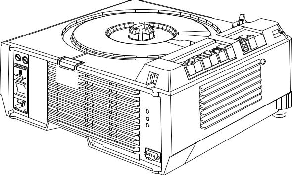
EKTAPRO Model 7020
figure 2-3
Features and Functions:
All features and functions as Model 4020.
Additional features:
Application Slot |
: |
for Kodak and OEM ADAPTERS |
Bus CONNECTORS (RS232) : |
IN (female) and OUT (male) |
|
Address Switch |
: |
16 addresses can be selected |
Initializing procedure |
: |
After power on the Projector the SLIDE LIFTER and the RING DRIVE |
|
|
will be checked, the LAMP and the FAN will be switched off |
High Light |
: |
20% more light output, lamp life time approx. 30% reduced |
NEW (only on Models 7020/9020)
If the parallel Mode “970*” is set on the IR Remote Control it is possible to toggle with “666*” between two projectors to control the focus functions. These functions are only visible on the screen.
Kodak AG, Stuttgart |
2-5 |
03/98 |

Service Manual |
SM 2547-1 |
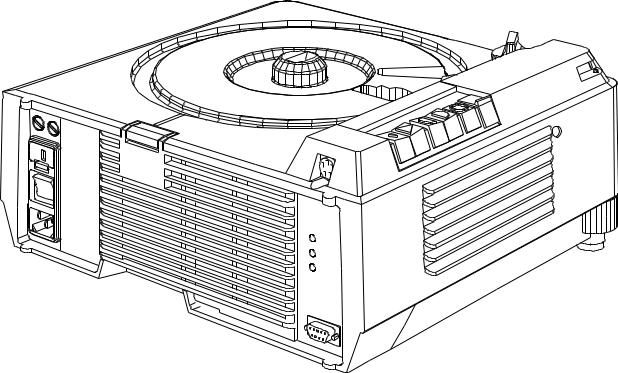
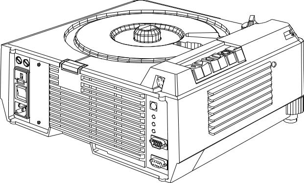
EKTAPRO Model 9020
figure 2-4
Features and Functions:
This multi purpose Projector has all of the features of the EKTAPRO 7020.
Additional features include: |
|
|
AUTO-ZERO function: |
: When the Projector senses an empty, gate the Projector automatically |
|
|
|
returns the tray to zero and begins the projection cycle again. |
|
|
This function can be deenergized. |
Timer |
: |
Slide change can be set from 1 up to 60 sec. |
AUTO FOCUS |
: |
Same as in EKTAPRO 5020 |
High Light |
: |
20% more light output, lamp life time approx. 30% reduced |
NOTE (new Model EKTAPRO 920/CINE)
For special applications (cinema promotion) the Model EKTAPRO 920/CINE is available. This model has a build in memory function which knows the last projected slide after switching off the projector.
Switching the projector on again the slide tray will run into that position after the initialization procedure. If the timer is switched on at that time a soft dissolve will be started immediately.
New parts (NAMEPLATE and MICROCONTROLLER) see Illustrated parts list.
03/98 |
2-6 |
Kodak AG, Stuttgart |
SM 2547-1 Service Manual
Overview
|
|
|
|
Model |
|
|
|
FUNCTIONS/ACCESSORIES |
|
|
|
|
|
|
|
4020 |
5020 |
7020 |
9020 |
|
|
|
|
||||
|
|
|
|
|
|
|
|
DUAL LAMP MODULE (Extra BRIGHT) |
|
X |
X |
X |
X |
|
|
|
|
|
|
|
|
TIMER |
|
- |
X |
- |
X |
|
|
|
|
|
|
|
|
AUTO-ZERO |
|
- |
- |
- |
X |
|
|
|
|
|
|
|
|
ADDRESS SWITCH |
|
- |
- |
X |
X |
|
|
|
|
|
|
|
|
APPLICATION SLOT |
|
- |
- |
X |
X |
|
|
|
|
|
|
|
|
AUTO FOCUS |
|
- |
X |
- |
X |
|
|
|
|
|
|
|
|
PRESENTATION BUS “IN” |
|
X |
X |
X |
X |
|
|
|
|
|
|
|
|
PRESENTATION BUS “OUT” |
|
- |
- |
X |
X |
|
|
|
|
|
|
|
|
RANDOM ACCESS |
|
X |
X |
X |
X |
|
|
|
|
|
|
|
|
EXTERNAL DIAGNOSTICS |
|
X |
X |
X |
X |
|
|
|
|
|
|
|
|
|
|
|
|
|
|
|
|
|
|
|
|
|
|
12/7-PIN MODULE |
|
- |
- |
O |
O |
|
|
|
|
|
|
|
|
SLIDE SYNCHRONIZER (1000Hz) |
|
- |
- |
O |
O |
|
|
|
|
|
|
|
|
TWIN SOCKET |
|
O |
O |
O |
O |
|
|
|
|
|
|
|
|
CABLE REMOTE |
|
O |
O |
O |
O |
|
|
|
|
|
|
|
|
IR REMOTE SYSTEM RA |
|
O |
O |
O |
O |
|
|
|
|
|
|
|
|
IR REMOTE SYSTEM RA/LP |
|
O |
O |
O |
O |
|
|
|
|
|
|
|
X = Standard Feature O = Accessory |
- not possible |
|
|
|
||
Kodak AG, Stuttgart |
2-7 |
03/98 |
Service Manual
Accessories
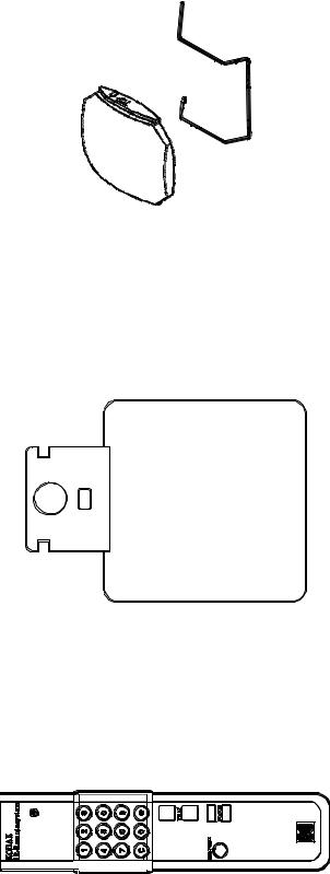
DUAL LAMP MODULE
CAT No. 718 4369
CABLE REMOTE
CAT No. 712 1080
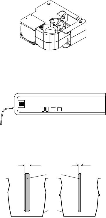
HEAT ABSORBING GLASS with CLIP
(not installed in Model 3020) CAT No. 717 7140 (6mm thick) CAT No. 717 7157 (3mm thick)
see NEWSLETTER #3/MAY/1996 page 5
SM 2547-1
figure 2-5
figure 2-6
6mm |
3mm |
HEAT ABSORBING
GLASS
CLIP
figure 2-7
03/98 |
2-8 |
Kodak AG, Stuttgart |
SM 2547-1 |
Service Manual |
CONDENSER KIT 4X4 (with CLIP)
CAT No. 714 4967
figure 2-8
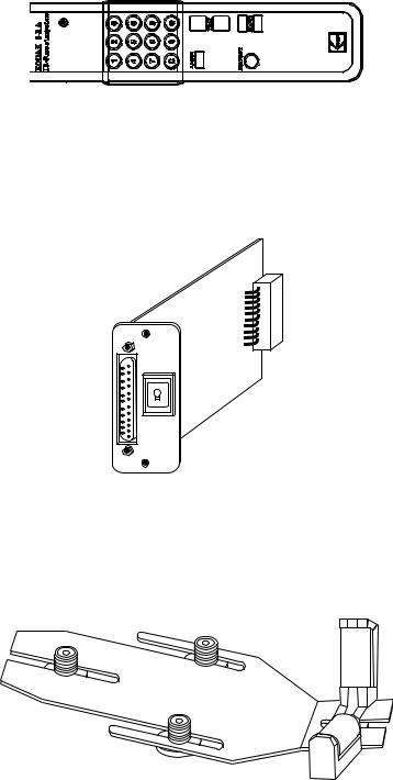
IR REMOTE System RA (with Random Access) CAT No. 712 1072
complete with RECEIVER and TRANSMITTER
RECEIVER
figure 2-9
TRANSMITTER
figure 2-10
Kodak AG, Stuttgart |
2-9 |
03/98 |
Service Manual |
SM 2547-1 |
IR REMOTE System RA/LP (Laser Pointer)
CAT No. 712 1064 complete with RECEIVER
TRANSMITTER
RECEIVER as use with IR REMOTE System RA.
figure 2-11
12/7-PIN MODULE
CAT No. 712 5875
Int.
Ext.
figure 2-12
LENS SUPPORT
CAT No. 715 1335
figure 2-13
03/98 |
2-10 |
Kodak AG, Stuttgart |
SM 2547-1 |
Service Manual |
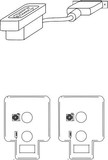
12/7-PIN ADAPTER CABLE
CAT No. 712 5883
figure 2-14
TWIN SOCKET ADAPTER
CAT No. 712 5909
see NEWSLETTER #3/MAY/1996 page 7
B C
figure 2-15
Kodak AG, Stuttgart |
2-11 |
03/98 |
Service Manual |
SM 2547-1 |
SLIDE SYNCHRONIZER
CAT No. 712 5891 (not available)
see page 16 OEM ACCESSORIES
LAMPS
Catalog No. |
Description |
145 2259 |
EXR 82V/300 W |
147 7678 |
EHS 82V/300 W |
145 2143 |
EXY 82V/250 W |
Lifetime
life time about 35 hours life time about 70 hours life time about 200 hours
03/98 |
2-12 |
Kodak AG, Stuttgart |
SM 2547-1 Service Manual
Specification
Electrical Supply |
: |
120/220/230/240 V |
|
: |
or 100/220 V |
|
: |
50/60 Hz |
Power Consumption |
: |
380 W |
Dimensions |
: |
310 x 355 x 145 mm max. (l/w/h) with tray and lens |
|
|
(12.2 x 14 x 5.7 in) |
Weight |
: |
6300 g (13.9 lb) |
Slide size |
: |
24 x 36 mm (0.9 x 1.4 in) |
Slide change time |
: |
<0,8 s |
Slide search time |
: |
<3 s |
Slide temperature |
: |
50°C (104°F) max. above room temperature |
LAMP (standard) |
: |
EXR 82V/300W |
Automatic LAMP change : |
0.3 s |
|
Operating temperature |
: |
0°C to 40°C (32°F to 113°F) |
Humidity |
: |
20 to 85% r.H. |
Air consumption |
: |
approx. 700 l/min. (20,000 cuft/min.) |
Approvals |
: |
VDE, UL , CSA |
Leveling |
: |
0° to 18° with internal elevation mechanism 30° max. allowed |
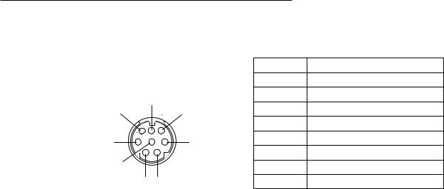
CONNECTORS
Remote SOCKET on Projector:
Type Mini DIN |
|
PIN No. |
Signal |
|
|
1 |
12 VDC |
||
|
|
|||
7 |
|
2 |
Gnd |
|
8 |
6 |
3 |
Signal 1 (LSB) |
|
4 |
Signal 2 |
|||
|
|
|||
5 |
3 |
5 |
Signal 3 |
|
6 |
Signal 4 |
|||
|
|
|||
4 |
|
7 |
Signal 5 (MSB) |
|
2 1 |
|
8 |
Interrupt |
|
(viewed from front ) |
12 V DC = |
|
||
|
|
average value between 7.2 and 14.5 V DC |
||
figure 2-16
Kodak AG, Stuttgart |
2-13 |
03/98 |
Service Manual |
SM 2547-1 |
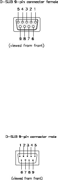
P-Bus / RS 232 “IN”
PIN No. |
Signal |
|
|
1 |
Connected to 4 and 6 |
|
|
2 |
Receive Data (RxD) |
|
|
3 |
Transmit Data (TxD) |
|
|
4 |
Connected to 1 and 6 |
|
|
5 |
Signal Ground |
|
|
6 |
Connected to 1 and 4 |
|
|
7 |
- |
8 |
- |
9 |
- |
figure 2-17
P-Bus / RS 232 “OUT”
PIN No. |
Signal |
|
|
1 |
Connected to 4 and 6 |
|
|
2 |
Transmit Data (TxD)v |
|
|
3 |
Receive Date (RxD) |
|
|
4 |
Connected to 1 and 6 |
|
|
5 |
Signal Ground |
|
|
6 |
Connected to 1 and 4 |
|
|
7 |
- |
8 |
- |
9 |
- |
figure 2-18
03/98 |
2-14 |
Kodak AG, Stuttgart |
SM 2547-1
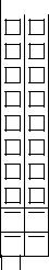
ACCESSORY SLOT
a |
|
|
b |
1 |
|
1 |
|
2 |
|
2 |
|
3 |
|
3 |
|
4 |
|
4 |
|
5 |
|
5 |
|
6 |
|
6 |
|
7 |
|
7 |
|
8 |
8 |
||
9
 9
9
10
 10
10
figure 2-19
Service Manual
PIN No. |
Signal |
|
|
a 1 |
SDA (I2C Data) |
a 2 |
I2C_INT (Interrupt) |
a 3 |
SLOT_232_R, TTL Level |
|
|
a 4 |
not used |
|
|
a 5 |
SLOT_A |
|
|
a 6 |
SLOT_C |
|
|
a 7 |
not used |
|
|
a 8 |
12V DC 200mA max. |
|
|
a 9 |
34V DC 750mA max. |
|
|
a 10 |
26V AC_N 750mA max. |
|
|
b 1 |
SLC (I2C Clock) |
b 2 |
PLL_DISS |
|
|
b 3 |
SLOT_232_T (TTL-Level) |
|
|
b 4 |
SLOT_DIS |
|
|
b 5 |
SLOT_B |
|
|
b 6 |
SL_DISS |
|
|
b 7 |
not used |
|
|
b 8 |
VSS 12 (Ground) |
|
|
b 9 |
VSS 34 (Ground) |
|
|
b 10 |
26V AC_L |
|
|
Kodak AG, Stuttgart |
2-15 |
03/98 |
Service Manual |
SM 2547-1 |
OEM ACCESSORIES
COPYRIGHT
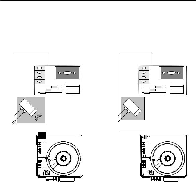
The adapter of this English company is only designed to use traditional AV cassette recorders. Cue pulses recorded on the tape trigger the interface unit to generate digital commands to advance the EKTAPRO Projector. It is an interesting feature that the adapter works either by plugging directly into the remote socket or works remotely by additional use of the EKTAPRO IR Receiver. In this case the system can simultaneously used with both the EKTAPRO IR Transmitter and the adapter. The adapter is powered by a 9 volt A PP3 battery.
The illustration (figure 2-20) shows both possibilities to run the Projectors.
 EKTAPRO IR Receiver
figure 2-20
IR-USE.
The advantage is that the Adapter and Projector can be separated. In addition, the use of the EKTAPRO Remote Transmitter is possible without disconnecting the Adapter.
CABLE USE
If no IR receiver is available the Adapter can be plugged with the fixed installed cable to the remote socket.
03/98 |
2-16 |
Kodak AG, Stuttgart |
 Loading...