


KitchenAid KBNU487TSS, KBNU367TSS, KBNU487VSS, KBNU361VSS, KBNU271VSS User Manual
...BUILT-IN OUTDOOR GRILLS
InstallationInstructionsandUse&CareGuide
For questions about features, operation/performance, parts, accessories or service, call: 1-800-422-1230 or visit our website at www.kitchenaid.com
In Canada, for assistance, installation and service, call: 1-800-807-6777 or visit our website at www.KitchenAid.ca
GRILS D'EXTÉRIEUR ENCASTRÉS
Instructionsd’installationetGuided’utilisationetd’entretien
Au Canada, pour assistance, installation ou service composez le 1-800-807-6777 ou visitez notre site Web à www.KitchenAid.ca
Table of Contents/Table des matières............................................................................. |
4 |
IMPORTANT:
Save for local electrical inspector's use.
Installer: Leave installation instructions with the homeowner.
Homeowner: Keep installation instructions for future reference.
IMPORTANT :
À conserver pour consultation par l'inspecteur local des installations électriques. Installateur : Remettre les instructions d'installation au propriétaire. Propriétaire : Conserver les instructions d'installation pour référence ultérieure.
Models/Modèles KBNU271VSS, KBNU361VSS, KBNU367VSS, KBNU487VSS, KBNS271TSS,
KBNS361TSS, KBNU367TSS, KBNU487TSS
W10175730A
OUTDOOR GRILL SAFETY
Your safety and the safety of others are very important.
We have provided many important safety messages in this manual and on your appliance. Always read and obey all safety messages.
This is the safety alert symbol.
This symbol alerts you to potential hazards that can kill or hurt you and others.
All safety messages will follow the safety alert symbol and either the word “DANGER” or “WARNING.” These words mean:
 DANGER
 WARNING
You can be killed or seriously injured if you don't immediately follow instructions.
You can be killed or seriously injured if you don't follow instructions.
All safety messages will tell you what the potential hazard is, tell you how to reduce the chance of injury, and tell you what can happen if the instructions are not followed.
 DANGER
If you smell gas:
1.Shut off gas to the appliance.
2.Extinguish any open flame.
3.Open lid.
4.If odor continues, keep away from the appliance and immediately call your gas supplier or your fire department.
 WARNING
1.Do not store or use gasoline or other flammable liquids or vapors in the vicinity of this or any other appliance.
2.An LP cylinder not connected for use shall not be stored in the vicinity of this or any other appliance.
State of California Proposition 65 Warnings:
WARNING: This product contains a chemical known to the State of California to cause cancer.
WARNING: This product contains a chemical known to the State of California to cause birth defects or other reproductive harm.
In the State of Massachusetts, the following installation instructions apply:
■Installations and repairs must be performed by a qualified or licensed contractor, plumber, or gasfitter qualified or licensed by the State of Massachusetts.
■If using a ball valve, it shall be a T-handle type.
■A flexible gas connector, when used, must not exceed 3 feet.
IMPORTANT: This grill is manufactured for outdoor use only. For grills that are to be used at elevations above 2000 ft (609.6 m) orifice conversion is required. See “Gas Supply Requirements” section. It is the responsibility of the installer to comply with the minimum installation clearances specified on the model/serial rating plate. The model/serial rating plate for built-in models can be found on the right-hand side of the grill.
2

IMPORTANT SAFETY INSTRUCTIONS
WARNING: To reduce the risk of fire, electrical shock, injury to persons, or damage when using the outdoor cooking gas appliance, follow basic precautions, including the following:
■Do not install portable or built-in outdoor cooking gas appliances in or on a recreational vehicle, portable trailer, boat or in any other moving installation.
■Always maintain minimum clearances from combustible construction, see “Location Requirements” section.
■The outdoor cooking gas appliance shall not be located under overhead unprotected combustible construction.
■This outdoor cooking gas appliance shall be used only outdoors and shall not be used in a building, garage, or any other enclosed area.
■Keep any electrical supply cord and fuel supply hose away from any heated surfaces.
■Keep outdoor cooking gas appliance area clear and free from combustible materials, gasoline and other flammable vapors and liquids.
■Do not obstruct the flow of combustion and ventilation air. Keep the ventilation openings of the cylinder enclosure free and clear from debris.
■Inspect the gas cylinder supply hose before each use of the outdoor cooking gas appliance. If the hose shows excessive abrasion or wear, or is cut, it MUST be replaced before using the outdoor cooking gas appliance. Contact your dealer and use only replacement hoses specified for use with the outdoor cooking gas appliance.
■Visually check the burner flames. They should be blue. Slight yellow tipping is normal for LP gas.
■Check and clean burner/venturi tube for insects and insect nest. A clogged tube can lead to fire under the outdoor cooking gas appliance.
■The LP gas supply cylinder to be used must be:
-constructed and marked in accordance with the Specification for LP Gas Cylinders of the U.S. Department of Transportation (DOT) or the National Standard of Canada, CAN/CSA-B339, Cylinders, Spheres, and Tubes for Transportation of Dangerous Goods; and Commission.
-provided with a listed overfilling prevention device.
-provided with a cylinder connection device compatible with the connection for outdoor cooking gas appliances.
■Always check connections for leaks each time you connect and disconnect the LP gas supply cylinder. See “Installation Instructions” section.
■When the outdoor cooking gas appliance is not in use, the gas must be turned off at the supply cylinder.
■Storage of an outdoor cooking gas appliance indoors is permissible only if the cylinder is disconnected and removed from the outdoor cooking gas appliance.
■Cylinders must be stored outdoors and out of the reach of children and must not be stored in a building, garage, or any other enclosed area.
■The pressure regulator and hose assembly supplied with the outdoor cooking gas appliance must be used. A replacement pressure regulator and hose assembly specific to your model is available from your outdoor cooking gas appliance dealer.
■Gas cylinder must include a collar to protect the cylinder valve.
■For appliances designed to use a CGA791 Connection: Place a dust cap on cylinder valve outlet whenever the cylinder is not in use. Only install the type of dust cap on the cylinder valve outlet that is provided with the cylinder valve. Other types of caps or plugs may result in leakage of propane.
If the following information is not followed exactly, a fire causing death or serious injury may occur.
■Do not store a spare LP gas cylinder under or near this outdoor cooking gas appliance.
■Never fill the cylinder beyond 80 percent full.
SAVE THESE INSTRUCTIONS
3

TABLE OF CONTENTS |
|
OUTDOOR GRILL SAFETY............................................................ |
2 |
INSTALLATION REQUIREMENTS ................................................ |
5 |
Tools and Parts ............................................................................ |
5 |
Location Requirements................................................................ |
6 |
Product Dimensions..................................................................... |
6 |
Cabinet Cutout Dimensions......................................................... |
7 |
Electrical Requirements ............................................................. |
10 |
Gas Supply Requirements ......................................................... |
11 |
Gas Connection Requirements - |
|
For Models Equipped for LP Gas 11 ......................................... |
11 |
Gas Connection Requirements - |
|
For Models Equipped for Natural Gas....................................... |
13 |
INSTALLATION INSTRUCTIONS ................................................ |
14 |
Built-in Outdoor Grill Installation................................................ |
14 |
Install Tank Tray for 20 lb LP Gas Fuel Tank - |
|
For Models Equipped for Use with a 20 lb LP Tank.................. |
14 |
GAS CONVERSIONS................................................................... |
18 |
For Models Equipped for Use with a 20 lb LP gas Tank........... |
18 |
Tools and Parts for Gas Conversion.......................................... |
18 |
Conversion to a Local LP Gas Supply....................................... |
19 |
Conversion from LP Gas to Natural Gas ................................... |
20 |
Check and Adjust the Burners................................................... |
22 |
OUTDOOR GRILL USE ................................................................ |
23 |
ELECTRONIC GRILL DISPLAY ................................................... |
24 |
Display........................................................................................ |
24 |
Start/Reset ................................................................................. |
24 |
Mode .......................................................................................... |
24 |
Using Your Outdoor Grill............................................................ |
25 |
Using Your Infrared Sear Burner................................................ |
27 |
Using Your Rotisserie................................................................. |
27 |
Rotisserie Cooking Tips ............................................................. |
29 |
Using Your Smoker Box ............................................................ |
29 |
Hood Lights................................................................................ |
30 |
TIPS FOR OUTDOOR GRILLING ................................................ |
30 |
Cooking Methods....................................................................... |
30 |
Grilling Chart............................................................................... |
31 |
OUTDOOR GRILL CARE ............................................................. |
33 |
Changing the Light Bulb ............................................................ |
33 |
Replacing the Batteries.............................................................. |
33 |
General Cleaning........................................................................ |
34 |
TROUBLESHOOTING .................................................................. |
36 |
ASSISTANCE OR SERVICE......................................................... |
37 |
In the U.S.A. ............................................................................... |
37 |
Accessories ................................................................................ |
37 |
In Canada ................................................................................... |
37 |
WARRANTY .................................................................................. |
38 |
TABLE DES MATIÈRES |
|
SÉCURITÉ DU GRIL D'EXTÉRIEUR ........................................... |
40 |
EXIGENCES D'INSTALLATION ................................................... |
42 |
Outillage et pièces...................................................................... |
42 |
Exigences d'emplacement......................................................... |
43 |
Dimensions du produit .............................................................. |
43 |
Dimensions de la cavité du placard........................................... |
44 |
Spécifications électriques .......................................................... |
47 |
Spécifications de l'alimentation en gaz ..................................... |
48 |
Exigences concernant le raccordement au gaz - |
|
Pour les modèles équipés pour le propane............................... |
48 |
Exigences concernant le raccordement au gaz - |
|
Pour les modèles équipés pour le gaz naturel........................... |
50 |
INSTRUCTIONS D’INSTALLATION............................................ |
50 |
Installation du gril d'extérieur encastré...................................... |
50 |
Installation du chariot de bouteille de gaz propane de 20 lb - |
|
Pour les modèles équipés pour l'utilisation d'une bouteille |
|
de gaz propane de 20 lb ............................................................ |
51 |
CONVERSIONS DE GAZ.............................................................. |
55 |
Pour les modèles équipés pour l'utilisation d'une bouteille de gaz |
|
propane de 20 lb ........................................................................ |
55 |
Outillage et pièces...................................................................... |
55 |
Conversion au gaz propane local .............................................. |
56 |
Conversion du gaz propane au gaz naturel............................... |
57 |
Contrôle et réglage des brûleurs................................................ |
60 |
UTILISATION DU GRIL D'EXTÉRIEUR....................................... |
61 |
AFFICHEUR ÉLECTRONIQUE DU GRIL .................................... |
61 |
Afficheur ..................................................................................... |
61 |
Start/Reset (démarrage/réinitialisation)...................................... |
61 |
Mode........................................................................................... |
61 |
Utilisation du gril d'extérieur....................................................... |
63 |
Utilisation du brûleur à infrarouge.............................................. |
64 |
Utilisation du tournebroche........................................................ |
64 |
Conseils de cuisson à l’aide du tournebroche .......................... |
66 |
Utilisation du fumoir ................................................................... |
67 |
Lampes du capot ....................................................................... |
67 |
CONSEILS POUR L'UTILISATION DU GRIL D'EXTÉRIEUR .... |
68 |
Méthodes de cuisson................................................................. |
68 |
Tableau de cuisson au gril ......................................................... |
69 |
ENTRETIEN DU GRIL D'EXTÉRIEUR ......................................... |
71 |
Changement de l'ampoule d'éclairage...................................... |
71 |
Remplacement des piles............................................................ |
71 |
Nettoyage général ...................................................................... |
72 |
DÉPANNAGE................................................................................. |
74 |
ASSISTANCE OU SERVICE......................................................... |
75 |
Au Canada.................................................................................. |
75 |
Accessoires ................................................................................ |
75 |
GARANTIE..................................................................................... |
75 |
4

INSTALLATION REQUIREMENTS
Tools and Parts
Gather the required tools and parts before starting installation. Read and follow the instructions provided with any tools listed here.
20 lb LP Gas Models
Tools Needed
■ |
Tape measure |
■ |
Wrench or pliers |
■ |
Small, flat-blade screwdriver |
■ |
Pipe wrench |
■ |
Flat-blade screwdriver |
■ |
Scissors or cutting pliers |
■ #2 and #3 Phillips screwdriver |
|
(to remove tiedowns) |
|
|
Noncorrosive leak- |
||
■ |
Level |
■ |
|
|
detection solution |
||
|
|
|
|
Parts Supplied
■Gas pressure regulator/hose assembly set for 11" WCP LP gas (attached to manifold).
■Rotisserie motor mounting bracket
■Rotisserie motor
■Rotisserie forks
■Rotisserie spit
■Smoker box
■1 single-prong plug/500 mAmp transformer assembly for the rotisserie motor
■1 single-prong plug/5,000 mAmp transformer assembly for the grill (power supply)
■Convertible regulator set for 4" WCP Natural gas
■Conversion kit for Natural gas
■LP gas fuel tank tray
■1.5 V “D” size Alkaline batteries
■Vinyl grill cover
Parts Needed - 20 lb LP gas models
■20 lb LP gas fuel tank - approximately 18" (45.7 cm) height and 12" (30.5 cm) diameter
Natural Gas Models
Tools Needed
■ |
Tape measure |
■ |
Wrench or pliers |
■ |
Small, flat-blade screwdriver |
■ |
Pipe wrench |
■ |
Flat-blade screwdriver |
■ |
Scissors or cutting pliers |
■ #2 and #3 Phillips screwdriver |
|
(to remove tiedowns) |
|
|
Noncorrosive leak- |
||
■ |
Level |
■ |
|
|
detection solution |
||
|
|
|
|
Parts Supplied
■Convertible regulator set for 4" WCP Natural gas
■1 single-prong plug/500 mAmp transformer assembly for the rotisserie motor (on some models)
■1 single-prong plug/5000 mAmp transformer assembly for the grill (power supply)
■1.5-volt “D” size alkaline battery (on some models)
■Rotisserie motor mounting bracket (on some models)
■Rotisserie motor (on some models)
■Rotisserie forks (on some models)
■Rotisserie spit (on some models)
■Smoker box (on some models)
Parts Needed
■Gas line shutoff valve
■½" male pipe thread nipple for connection to pressure regulator
■LP gas-resistant pipe-joint compound
■CSA design-certified outdoor flexible stainless steel appliance connector (4-5 ft [1.2-1.5 m]) or rigid gas supply line as needed
5
LocationRequirements
 WARNING
Explosion Hazard
Do not store fuel tank in a garage or indoors.
Do not store grill with fuel tank in a garage or indoors.
Failure to follow these instructions can result in death, explosion, or fire.
Select a location that provides minimum exposure to wind and traffic paths. The location should be away from strong draft areas.
Do not obstruct flow of combustion and ventilation air.
Clearance to combustible construction for built-in outdoor grills:
■A minimum of 24" (58 cm) must be maintained between the front of the grill hood, sides and back of the grill and any combustible construction.
■A 24" (58 cm) minimum clearance must also be maintained below the cooking surface and any combustible construction.
 WARNING
Fire Hazard
Do not use grill near combustible materials. Do not store combustible materials near grill. Doing so can result in death or fire.
Rotisserie
A 6" (15.2 cm) minimum clearance is needed for the rotisserie motor.
A grounded, 3-prong outdoor GFI outlet is to be located to the left of the grill. See “Electrical Requirements” section.
NOTE: The rotisserie is an accessory on some models. See the “Assistance or Service” section to order.
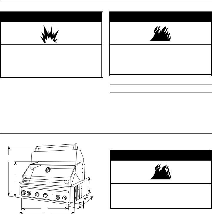
ProductDimensions
36¼" (92.1 cm)
23¾" (60.5 cm)
10⁄"
(27.1 cm)

 28½" (72.4 cm)
A |
22¾" |
B |
(57.7 cm) |
A.27" (68.6 cm) 36" (91.4 cm) 48" (121.9 cm)
B.27" (68.6cm) models - 31¾" (80.6 cm) 36" (91.4 cm) models - 40¾" (103.4 cm) 48" (121.9 cm) models - 52¾" (133.9 cm)
Built-in Outdoor Grill Non-Combustible Enclosure
 WARNING
Fire Hazard
Do not install grill on or near combustible materials.
Doing so can result in death or fire.
The enclosure for the built-in outdoor grill is to be a minimum of 11" (28.0 cm) high x 23" (58.4 cm) deep with a width of
30" (76.0 cm) for 27" (68.6 cm) grills, 39" (99.0 cm) for
36" (91.4 cm) grills and 51" (129.5 cm) for 48" (121.9 cm) grills.
This built-in outdoor grill is only for installation in a built-in enclosure constructed only of non-combustible materials. Noncombustible materials could be brick, firewall or steel. Do not use wood or other combustible materials for built-in enclosure.
Built-in Outdoor Grill Combustible Enclosure
An insulated jacket is required if the built-in grill is to be used in a combustible enclosure application. See “Assistance or Service” section or your grill dealer to order the insulated jacket kit for your model.
6
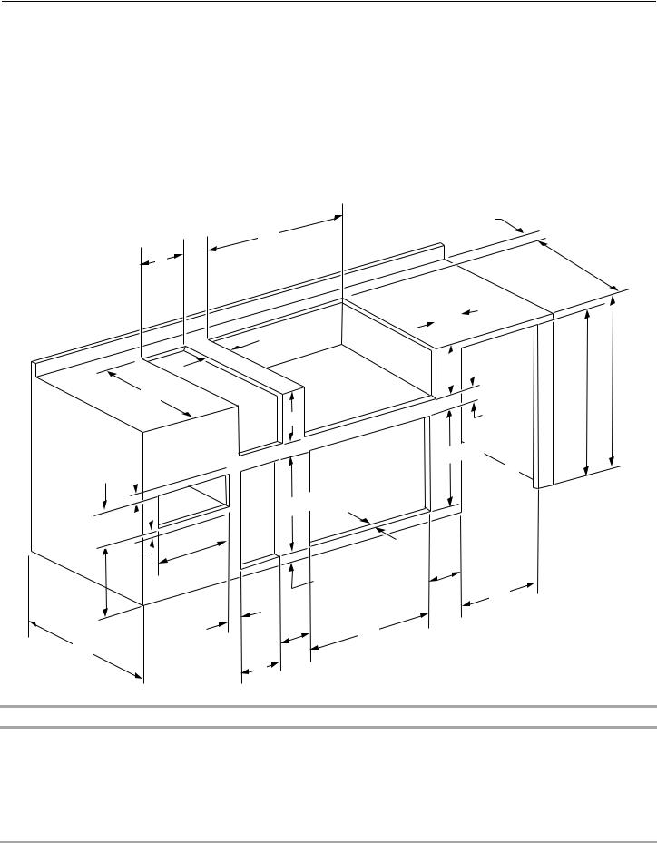
CabinetCutoutDimensions
Enclosure and clearance dimensions that are shown must be used. Given dimensions provide required clearances.
The installation of this grill must conform with local codes or, in the absence of local codes, with either the National Fuel Gas Code, ANSI Z223.1/NPFA 54, Natural Gas and Propane Installation Code, CSA B149.1, or Propane Storage and Handling Code, B149.2.
Copies of the standards listed may be obtained from:
CSA International
8501 East Pleasant Valley Rd.
Cleveland, Ohio 44131-5575
NOTE: The grill drops into the opening and is supported by its side flanges. Do not use a bottom support.
The dimension chart and illustration below include cutout dimensions and minimum spacing requirements for all built-in outdoor products. The illustration is for reference. The design of your cabinet layout can be personalized, but the dimensions for the cutouts and minimum spacing must be followed.
C
C
|
|
|
|
. |
|
|
|
.5 cm) |
min |
12" |
|
|
||
|
accessory |
|||
|
|
(30 |
|
|
to |
any |
|
|
|
|
|
|
|
|
E
K
|
|
|
|
|
Warming |
|
|
|
" |
|
|
Drawer |
|
|
|
|
|
|||
|
|
|
|
|
|
|
|
|
|
|
|
|
|
|
¹⁄ |
|
|
|
|
|
9 |
|
|
|
|
|
|
.2 cm) |
|
|
||||
(23 |
|
|
|
|
|
|
|
|
|
K |
|
J |
|
|
|
|
. |
|
|
|
|
|
|
|
|
||
|
5" |
|
|
|||
|
min |
|
|
|||
.7 |
cm) |
|
|
|||
|
|
|
|
|||
(12 |
|
|
|
|
|
|
B
|
|
|
Grills |
or |
|
Centers |
|||
|
|
|
|
|
|
|
|
||
Side |
D |
|
Refreshment |
|
|||||
or |
|
|
|
|
|
|
|
|
|
Sear |
|
|
|
|
|
|
|
|
|
Burners |
|
|
|
|
|
|
|
|
|
|
|
|
|
|
|
|
|
Doors |
|
|
|
|
|
|
Access |
|
|||
|
|
|
.0 cm) |
|
|
||||
Utility |
|
" |
(53 |
|
|
|
|
|
|
|
⁄ |
|
|
|
|
|
|
|
|
or |
20 |
|
|
|
|
|
|
|
|
Trash |
|
|
|
|
|
|
|
|
|
Drawer |
|
|
|
|
|
|
|
|
L |
|
|
|
|
|
|
|
|
|
|
|
|
|
|
|
|
|
|
min |
. |
|
|
|
|
|
|
|
|
|
|
|
|
|
|
" |
(6 |
.4 |
cm) |
|
|
|
|
|
2¹⁄ |
|
|
||||
|
|
|
|
|
|
||||
|
|
|
|
|
|
|
|||
|
|
|
|
|
|
|
|
|
|
K |
K |
|
|
|
|
|
|
F |
|
|
|
|
|
|
|
|
|
||
M |
|
|
|
|
|
|
|
|
|
|
|
|
. |
|
|
.6 cm) |
min |
||
|
|
|||
3" |
(7 |
hood |
||
open |
||||
to |
|
|
||
|
|
|
||
|
|
|
|
|
|
|
|
|
|
|
|
|
|
E |
|
|
|
|
|
|
|
|
|
|
|
|
|
|
|
. |
|
|
|
|
|
|
|
|
|
|
|
|
|
|
|
|
|
|
|
|
|
|
|
|
|
|
|
|
|
|
|
|
|
12" |
min |
|
|
|
|
|
|
||||
|
|
|
|
|
|
|
|
|
|
|
|
|
||||||
|
|
|
|
|
|
|
|
|
any |
|
|
|
|
|
|
|||
|
|
|
|
|
|
|
|
|
|
|
|
|
|
|
||||
|
|
|
|
|
|
|
to |
|
|
|
|
|
|
|
|
|
||
|
|
|
|
|
|
|
accessory |
|||||||||||
|
|
|
|
|
|
|
|
|
|
|
|
|
|
|
|
|
|
|
|
|
|
|
|
|
|
|
|
|
|
|
|
|
|
|
|
|
|
|
|
|
|
|
|
|
|
|
|
|
|
|
|
|
|
|
|
|
|
|
|
|
|
|
|
|
|
|
|
|
|
|
|
|
|
|
|
|
D |
|
|
|
|
|
|
|
|
|
|
|
|
|
|
|
|
|
|
|
|
|
|
|
|
|
|
|
|
|
|
|
|
|
|||
|
|
|
|
|
|
|
|
|
|
|
|
|
|
|
|
A |
||
|
|
|
|
|
|
|
|
1¹⁄ |
" |
min |
. |
|
H |
|
||||
|
|
|
|
|
|
|
|
|||||||||||
|
|
|
|
|
|
|
|
|
|
|
|
|
||||||
|
|
|
|
|
|
|
|
|
|
|
|
|
||||||
|
|
|
|
|
|
|
|
|
|
|
|
|
||||||
|
|
|
|
|
|
|
|
|
|
|
|
|
|
|||||
|
|
|
(3 |
.8 |
|
cm) |
|
|
|
|
|
|
||||||
|
|
|
|
|
|
|
|
|
|
|
|
|||||||
|
|
|
|
|
|
|
|
|
|
|
|
|
|
|
||||
|
|
|
|
|
|
|
|
|
|
|
|
|
|
|
|
|||
|
|
|
|
|
|
.4 cm) |
|
|
|
|
|
|
||||||
|
|
|
" (52 |
|
|
|
|
|
|
|
|
|
|
|
|
|||
|
⁄ |
|
|
|
|
|
|
|
|
|
|
|
|
|
||||
20 |
|
|
|
|
|
|
|
|
|
|
|
|
|
|
|
|
|
|
|
|
|
|
|
Refrigerator |
|
||||||||||||
|
|
|
|
|
or |
|
Maker |
|
|
|
|
|
|
|||||
|
|
|
|
|
Ice |
|
|
|
|
|
|
|||||||
|
|
|
|
|
|
|
|
|
|
|
|
|
|
|
||||
K
G
Minimum Spacing Requirement Between Cutouts - Dimension K
Between 2 or more sets of Access Doors adjacent to each other:
K = 14" (35.6 cm) when 2 adjacent doors are opened to 90 degrees
K = 8" (20.3 cm) when 1 of the adjacent doors is opened to 90 degrees
Between a set of Access Doors and a Trash Drawer, Utility Drawer, Warming Drawer, Refrigerator, or Ice Maker:
K = 8" (20.3 cm) when 1 of the adjacent doors is opened to 90 degrees
Between a Trash Drawer, Utility Drawer, or Warming Drawer:
K = 3" (7.6 cm)
7

Cabinet Height and Depth Dimensions
|
Dimension A Minimum |
Dimension B Minimum |
|
|
|
With outdoor refrigerator |
37" (94.0 cm) |
26" (66.0 cm) |
|
|
|
Grill with insulated jacket |
36½" (92.7 cm) |
27" (68.6 cm) |
|
|
|
Grill without insulated jacket |
35½" (90.2 cm) |
26" (66.0 cm) |
|
|
|
Cutout Dimensions - Built-in Grill
Grill Size |
Dimension C |
Dimension D |
Dimension E |
|
|
|
|
|
|
27" (68.6 cm) |
29⁄" (75.2 cm) |
10¾" (27.3 cm) |
22⁄" (58.1 cm) |
|
|
|
|
|
|
36" |
(91.4 cm) |
38⁄" (98.1 cm) |
10¾" (27.3 cm) |
22⁄" (58.1 cm) |
|
|
|
|
|
48" |
(121.9 cm) |
50⁄" (128.6 cm) |
10¾" (27.3 cm) |
22⁄" (58.1 cm) |
|
|
|
|
|
Cutout Dimensions - Built-in Grill with Insulated Jacket
Grill Size |
Dimension C |
Dimension D |
Dimension E |
|
|
|
|
|
|
27" (68.6 cm) |
33" (83.8 cm) |
11¾" (29.8 cm) |
24" (61.0 cm) |
|
|
|
|
|
|
36" |
(91.4 cm) |
42" (106.7 cm) |
11¾" (29.8 cm) |
24" (61.0 cm) |
|
|
|
|
|
48" |
(121.9 cm) |
54" (137.2 cm) |
11¾" (29.8 cm) |
24" (61.0 cm) |
|
|
|
|
|
Cutout Dimensions - Built-in Side Burner
Burner Position |
Dimension C |
Dimension D |
Dimension E |
|
|
|
|
Front to Back |
13½" (34.3 cm) |
10¾" (27.3 cm) |
22⁄" (57.5 cm) |
|
|
|
|
Side by Side |
24½" (62.2 cm) |
10¾" (27.3 cm) |
16⁄" (42.9 cm) |
|
|
|
|
|
|
|
|
|
Cutout Dimensions - Built-in Sear Burner |
|
|
|
|
|
|
|
Dimension C |
Dimension D |
Dimension E |
|
|
|
|
|
13½" (34.3 cm) |
10⁄" (27.0 cm) |
22¹¹⁄" (57.6 cm) |
|
|
|
|
|
|
|
|
|
Cutout Dimensions - Built-in Refreshment Center |
|
|
|
|
|
|
|
Dimension C |
Dimension D |
Dimension E |
|
|
|
|
|
30½" (77.5 cm) |
10¾" (27.3 cm) |
23" (58.4 cm) |
|
|
|
|
|
|
|
|
|
Cutout Dimensions - Built-in Access Doors |
|
|
|
|
|
|
Door Size |
Dimension F |
Dimension L* |
|
|
|
|
|
18" (45.7 cm) |
16³⁄" (41.1 cm) |
1½" (3.8 cm) |
|
|
|
|
|
27" (68.6 cm) |
25¹⁄" (63.8 cm) |
1½" (3.8 cm) |
|
|
|
|
|
30" (76.2 cm) |
28¹⁄" (71.4 cm) |
1½" (3.8 cm) |
|
|
|
|
|
36" (91.4 cm) |
34¹⁄" (86.7 cm) |
1½" (3.8 cm) |
|
|
|
|
|
48" (121.9 cm) |
46¹⁄" (117.2 cm) |
1½" (3.8 cm) |
|
|
|
|
|
*Dimension L is the minimum mounting surface area around the opening for mounting the optional door or drawers.
8
Cutout Dimensions - Outdoor Refrigerator
|
Dimension G |
Dimension H |
|
|
|
|
24" (61.0 cm) |
35¼" (89.5 cm) |
|
|
|
|
|
|
|
Cutout Dimensions - Outdoor Ice Maker |
|
|
|
|
|
Dimension G |
Dimension H |
|
|
|
|
18" (45.7 cm) |
34" (86.4 cm) min. to 34½" (87.6 cm) max. |
|
|
|
|
|
|
|
Cutout Dimensions - Built-in Warming Drawer |
|
|
|
|
Warming Drawer Size |
Dimension J |
|
|
|
|
24" (61.0 cm) |
22½" (57.2 cm) |
|
|
|
|
|
|
|
|
Cutout Dimensions - Built-in Utility Drawer and Built-in Trash Drawer |
|
|
|
|
|
Dimension M |
Dimension L* |
|
|
|
|
12¼" (31.1 cm) |
1½" (3.8 cm) |
|
|
|
*Dimension L is the minimum mounting surface area around the opening for mounting the optional door or drawers.
Built-in Outdoor Grill Enclosure Ventilation for LP Gas:
An enclosure for an LP gas fuel tank is to be ventilated by openings at both the top and lower levels of the enclosure.
If converting to LP gas these vents are to be in the enclosure:
An enclosure for use with an LP gas fuel tank for built-in installation is to have at least one ventilation opening on an exposed exterior side located within 5" (12.7 cm) of the top is to be a minimum of 20 in.2 (129.0 cm2). One ventilation opening within 1" (2.5 cm) of the bottom of the enclosure and the bottom opening is to be a minimum of 10 in.2 (64.5 cm2). All vent openings are to be unobstructed. Every opening is to be a minimum of ¹⁄" (0.32 cm) wide.
20 in.2 (129.0 cm2) min. ventilation both sides
5" (12.7 cm) max.
1" (2.5 cm) max.
10 in.2 (64.5 cm2) min.  ventilation both sides
5" (12.7 cm) max.
9
ElectricalRequirements
 WARNING
Electrical Shock Hazard
Plug into a grounded 3 prong outlet.
Do not remove ground prong.
Do not use an adapter.
Do not use an extension cord.
Failure to follow these instructions can result in death, fire, or electrical shock.
If codes permit and a separate ground wire is used, it is recommended that a qualified electrician determine that the ground path is adequate.
Check with a qualified electrician if you are not sure whether the grill is properly grounded.
A 120-volt, 60-Hz, AC-only, 15-amp, fused electrical supply is required.
It is recommended that a separate circuit servicing only this grill be provided.
■To avoid electrical shock, do not immerse cord or plugs in water or other liquid.
■Unplug from the outlet when not in use and before cleaning. Allow to cool before putting on or taking off parts.
■Do not operate any outdoor cooking gas appliance with a damaged cord, damaged plug, or after the appliance malfunctions or has been damaged in any manner. Contact the manufacturer for repair.
■Do not let the cord hang over the edge of a table or touch hot surfaces.
■Do not use an outdoor cooking appliance for purposes other than intended.
■When connecting, first connect plug to the outdoor cooking gas appliance then plug appliance into the outlet.
■Use only a Ground Fault Interrupter (GFI) protected circuit with this outdoor cooking gas appliance.
■Do not remove the ground prong or use with an adapter of 2 prongs.
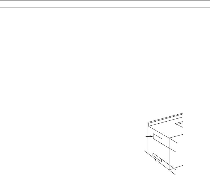
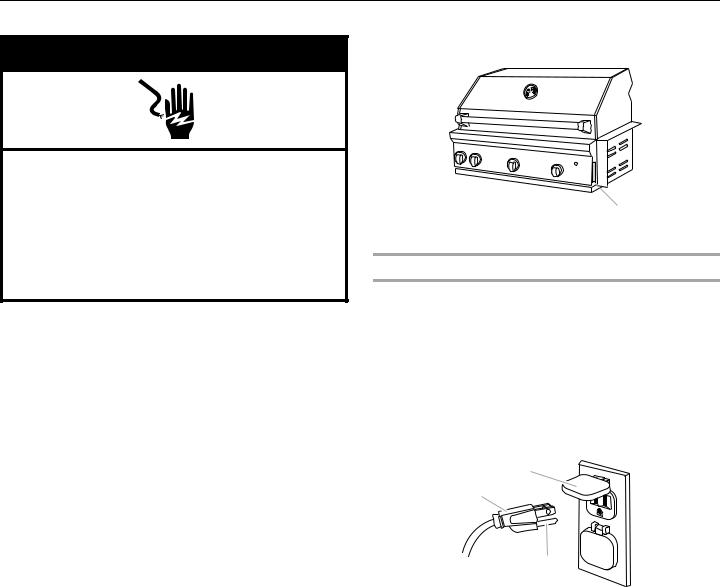
The model/serial number rating plate is located on the right-hand side of the grill. See the following illustration.
 A
A
A. Model/serial number plate
Recommended Ground Method
The outdoor grill, when installed, must be electrically grounded in accordance with local codes or, in the absence of local codes, with the National Electrical Code ANSI/NFPA 70, or Canadian Electrical Code, CSA C22.1.
Copies of the standards listed above may be obtained from:
CSA International
8501 East Pleasant Valley Rd.
Cleveland, Ohio 44131-5575
National Fire Protection Association
One Batterymarch Park
Quincy, Massachusetts 02269
B
A
C
A.3-prong ground plug
B.3-prong polarized type outdoor GFI outlet
C.Ground prong
10
GasSupplyRequirements
 WARNING
Explosion Hazard
Use a new CSA International approved “outdoor” gas supply line.
Securely tighten all gas connections.
If connected to LP, have a qualified person make sure gas pressure does not exceed 11” (28 cm) water column.
Examples of a qualified person include:
licensed heating personnel,
authorized gas company personnel, and authorized service personnel.
Failure to do so can result in death, explosion, or fire.
Observe all governing codes and ordinances.
IMPORTANT: This installation must conform with all local codes and ordinances. In the absence of local codes, installation must conform with American National Standard, National Fuel Gas Code ANSI Z223.1 - latest edition or CAN/CGA B149.1 - latest edition.
IMPORTANT: Grill must be connected to a regulated gas supply.
Refer to the model/serial rating plate for information on the type of gas that can be used. If this information does not agree with the type of gas available, check with your local gas supplier.
Gas Conversion:
No attempt shall be made to convert the grill from the gas specified on the model/serial rating plate for use with a different gas type without consulting the serving gas supplier. The conversion kit supplied with grill must be used. See “Gas Conversions” section for instructions.
Gas Pressure Regulator
The gas pressure regulator supplied with this grill must be used. The inlet (supply) pressure to the regulator should be as follows for proper operation:
LP Gas:
Operating pressure: 11" (27.9 cm) WCP
Inlet (supply) pressure: 11" to 14" (27.9 cm to 35.5 cm) WCP
Natural Gas:
Operating pressure: 4" (10.2 cm) WCP
Inlet (supply) pressure: 7" to 14" (17.8 cm to 35.5 cm) WCP maximum.
Contact local gas supplier if you are not sure about the inlet (supply) pressure.
Burner Requirements for High Altitude
Input ratings shown on the model/serial rating plate are for elevations up to 2,000 ft (609.6 m).
For elevations above 2,000 ft (609.6 m), ratings are reduced at a rate of 4% for each 1,000 ft (304.8 m) above sea level. Orifice conversion is required. See “Assistance or Service” section to order.
Gas Supply Line Pressure Testing
Testing above ½ psi (3.5 kPa) or 14" (35.5 cm) WCP (gauge):
The grill and its individual shutoff valve must be disconnected from the gas supply piping system during any pressure testing of that system at test pressures greater than ½ psig (3.5 kPa).
Testing below ½ psi (3.5 kPa) or 14" (35.5 cm) WCP (gauge) or lower:
The grill must be isolated from the gas supply piping system by closing its individual manual shutoff valve during any pressure testing of the gas supply piping system at test pressures equal to or less than ½ psig (3.5 kPa).
GasConnectionRequirements
ForModelsEquippedforLPGas
20 lb LP Gas Fuel Tank
This grill is equipped for use with a 20 lb LP gas fuel tank (fuel tank not supplied). A gas pressure regulator/hose assembly is supplied.
It is also design-certified by CSA International for local LP gas supply or for Natural gas with appropriate conversion.
A
A. Gas pressure regulator/hose assembly
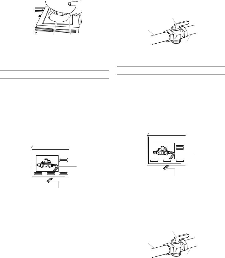
The 20 lb LP gas fuel tank must be mounted and secured.
Door Style Tank Tray
1.Open cabinet doors.
2.Pull out the tank tray.
Tank tray
3.Place the 20 lb LP gas fuel tank bottom collar into the mounting hole in the tank tray.
11
4.Tighten the locking screw against the bottom collar of the 20 lb LP gas fuel tank to secure.
A 
BC
A.Locking screw
B.Mounting hole
C.Bottom collar
5.Slide tank tray back into the cabinet.
6.Close cabinet doors.
Local LP Gas Supply Conversion
Conversion must be made by a qualified gas technician. The qualified gas technician shall provide the gas supply to the selected grill location in accordance with the National Fuel Gas Code ANSI Z223.1/NFPA 54 - latest edition, and local codes. For conversion to local LP, the convertible regulator in the conversion kit supplied with the grill must be used.
IMPORTANT: The gas installation must conform with local codes, or in the absence of local codes, with the National Fuel Gas Code, ANSI Z223.1/NFPA 54 - latest edition. The qualified LP gas technician shall provide the LP gas supply to the selected grill location in accordance with the National Fuel Gas Code, ANSI Z223.1/NFPA 54 and local codes.
Follow instructions for converting to local LP gas in the “Gas Conversions” section.
A
 B
B
C
A.New CSA International approved “outdoor” flexible gas supply line
B.Rear of grill
C.To local LP gas supply
The gas supply line shall be equipped with an approved shutoff valve. This valve should be located in the same area as the grill and should be in a location that allows ease of opening and closing. Do not block access to the shutoff valve. The valve is for turning on or shutting off gas to the grill.
B
A
C
A.Gas supply line
B.Shutoff valve “open” position
C.To grill
Natural Gas Conversion
Conversion must be made by a qualified gas technician. The qualified Natural gas technician shall provide the Natural gas supply to the selected grill location in accordance with the National Fuel Gas Code ANSI Z223.1/NFPA 54 - latest edition, and local codes. For conversion to Natural gas, the Natural gas conversion kit supplied with the grill must be used.
IMPORTANT: The gas installation must conform with local codes, or in the absence of local codes, with the National Fuel Gas Code, ANSI Z223.1/NFPA 54 - latest edition.
To convert to Natural gas, the Natural Gas Conversion Kit supplied with the grill must be used. Follow instructions for converting to Natural gas in the “Gas Conversions” section.
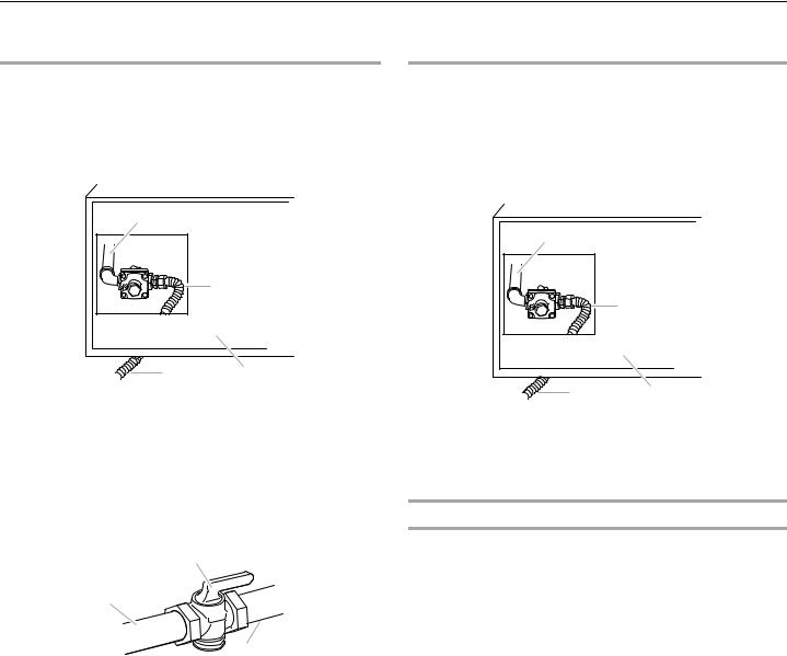
A
 B
B
C
A.New CSA International approved “outdoor” flexible gas supply line
B.Rear of grill
C.To Natural gas supply
The gas supply line shall be equipped with an approved shutoff valve. This valve should be located in the same area as the grill and should be in a location that allows ease of opening and closing. Do not block access to the shutoff valve. The valve is for turning on or shutting off gas to the grill.
B
A
C
A.Gas supply line
B.Shutoff valve “open” position
C.To grill
12
GasConnectionRequirements
For Models Equipped for Natural Gas
Natural Gas |
|
LP Gas Conversion Using a Local LP Gas Supply |
Built-in grill models are equipped for use with Natural gas. They are design-certified by CSA International for LP (propane or butane) gases with appropriate conversion.
Built-in models are set for Natural gas use and have a pressure regulator with ½" female pipe threads.
A |
|
|
B |
D |
C |
|
A.Grill gas pipe
B.New CSA International approved “outdoor” flexible gas supply line
C.Rear of grill
D.To Natural gas supply
The supply line shall be equipped with an approved shutoff valve. This valve should be located in the same area as the grill and should be in a location that allows ease of opening and closing. Do not block access to the shutoff valve. The valve is for turning on or shutting off gas to the grill.
B
A
C
A.Gas supply line
B.Shutoff valve “open” position
C.To grill
Conversion must be made by a qualified person. A qualified Natural gas technician shall provide the LP gas supply to the selected grill location in accordance with the National Fuel Gas Code ANSI Z223.1/NFPA 54 - latest edition, and local codes.
To convert to LP gas, the LP Gas Conversion Kit Part Number W10118099 must be used. Follow instructions included with kit.
A |
|
|
B |
D |
C |
|
A.Grill gas pipe
B.New CSA International approved “outdoor” flexible gas supply line
C.Rear of grill
D.To local gas supply
LP Gas Conversion Using a 20 lb LP Gas Fuel Tank
To convert to LP gas, the LP Gas Conversion Kit Part Number W10118099 must be used. Follow instructions included with kit. A 20 lb LP gas fuel tank must be purchased separately.
13
INSTALLATION INSTRUCTIONS
Built-inOutdoorGrillInstallation
 WARNING
Excessive Weight Hazard
Use two or more people to move and install grill. Failure to do so can result in back or other injury.
■Unpack grill. Remove all packaging materials and remove grill from carton.
■Place grill into outdoor enclosure, but leave enough room in back to connect to gas supply and electrical single prong plug-in.
■Open the hood.
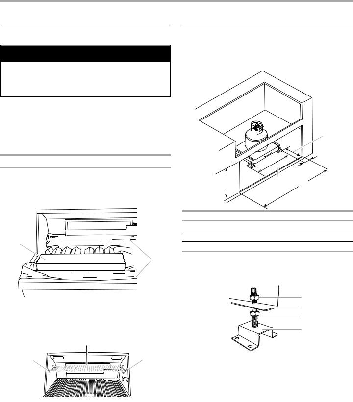
Remove Packaging Material Inside the Grill
1.Cut the tiedowns holding the grates together.
2.Remove warming shelf and grill grates from inside the grill and remove packaging material.
3.Remove foam block and wrap from inside the grill.
A
B
A.Foam block
B.Foam wrap
4.Replace the grill grates.
5.Place warming shelf on brackets as shown.
B
A |
A |
A.Warming shelf brackets
B.Warming shelf
6.Dispose of/recycle all packaging material.
InstallTankTrayfor20lbLP GasFuelTank
ForModelsEquippedforUsewitha20lbLPTank
1.Position the tank tray for 20 lb LP gas fuel tank in the island cabinet and determine the dimension for your grill size from the chart.
2¹⁄"
|
|
(5.7 cm) |
|
|
|
A |
|
20⁄" |
18³⁄" |
B |
|
(52.4 cm) |
(46.7 cm) |
||
|
|||
Built-In Grill Size |
Dimension A |
Dimension B |
|
27" (68.6 cm) |
3³⁄ " (8.6 cm) |
25¹⁄ " (63.8 cm) |
|
36" (91.4 cm) |
4" (10.2 cm) |
34¹⁄ " (86.7 cm) |
|
48" (121.9 cm) |
4" (10.2 cm) |
46¹⁄ " (117.2 cm) |
2.Square the tank tray mounting brackets and mark the mounting hole locations in the island base.
3.Remove the top nuts (4) from the tank tray assembly and lift the tank tray off of the mounting brackets.
A
B
C
D
E
A.Top nut
B.Tank tray
C.Bottom nut
D.Bolt
E.Mounting bracket
14
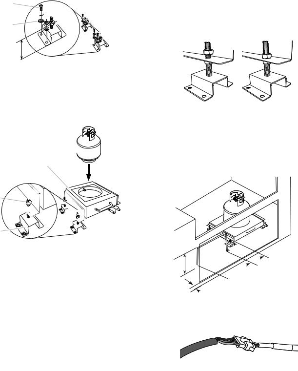
4.Install the tank tray mounting brackets to the base or floor of the island using the proper size and type of mounting hardware (not supplied). Tighten mounting hardware.
A 

B 


C 
3" (7.6 cm)
A.Screw (Use proper screw for island floor material.)
B.Lock washer
C.Flat washer
5.Pre-adjust each of the bottom nuts on the mounting brackets to 3" (7.6 cm) from the base of the island to the top of the nuts.
6.Remount the tank tray back onto the mounting brackets. Replace the 4 top nuts but do not tighten.
A 

B
C 

D
A.20 lb LP gas fuel tank
B.Tank tray for 20 lb gas fuel tank
C.Top nut (do not tighten)
D.Mounting bracket
7.The tank tray for the 20 lb LP gas fuel tank must be adjusted so that the bottom of the tank tray is ¹⁄" (0.32 cm) above the cabinet door opening and is level. The top nut on each of the mounting brackets is to be loose. Turn the bottom nuts counterclockwise to raise the tank tray and turn the bottom nuts clockwise to lower the tank tray. When the tank tray is level and slides in and out without touching the cabinet door opening at the bottom or top with the 20 lb LP tank installed, tighten the top nuts against the adjustment flange.
A B
A.Top nut loosened
B.Top nut tightened
NOTE: A bracket or shelf (not supplied) that is large enough to keep a second 20 lb LP gas fuel tank from being stored in the storage area under the grill is required to be mounted inside the island. Bracket dimensions are shown for reference.
 6" 11¹³⁄"
 (15.2 cm)
(30 cm)
 21" (53.3 cm) for 48" (121.9 cm) doors 9" (22.9 cm) for 36" (91.4 cm) doors
 2⁄" (6.8 cm)
8.Plug in the electrical connector from the back of the grill to the electrical connector from the 20 lb LP gas fuel tank tray.
A B
A.Electrical connector from 20 lb LP gas fuel tank tray
B.Electrical connector from back of grill
NOTE: These connectors must be plugged in for the electronic grill display and fuel shutoff valve to work. This electrical connection is required for all of the gas type applications.
15
Make Gas Connection
Gas Connection to a 20 lb LP Gas Fuel Tank
 WARNING
Explosion Hazard
Use a new CSA International approved “outdoor” gas supply line.
Securely tighten all gas connections.
If connected to LP, have a qualified person make sure gas pressure does not exceed 11” (28 cm) water column.
Examples of a qualified person include:
licensed heating personnel,
authorized gas company personnel, and authorized service personnel.
Failure to do so can result in death, explosion, or fire.
If converting to local LP or Natural gas, follow the instructions in the “Gas Conversions” section.
IMPORTANT: A 20 lb LP gas fuel tank must be purchased separately.
IMPORTANT: The gas pressure regulator/hose assembly supplied with the grill must be used. Replacement gas pressure regulator/hose assembly specific to your model, is available from your outdoor grill dealer.
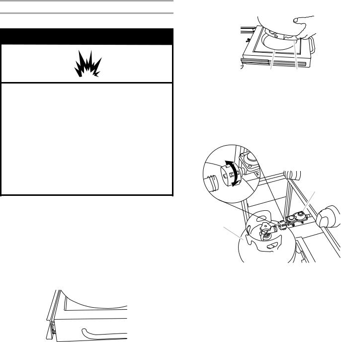
To Install the 20 lb LP Gas Fuel Tank:
1.Open cabinet doors.
2.Pull out the tank tray.
Tank tray
3.Place the 20 lb LP gas fuel tank bottom collar into the mounting hole in the tank tray.
4.Tighten the locking screw against the bottom collar of the 20 lb LP gas fuel tank to secure.
A 
BC
A.Locking screw
B.Mounting hole
C.Bottom collar
5.Screw the gas pressure regulator/hose assembly to the 20 lb LP gas fuel tank as shown. (To disconnect, turn off the gas supply to the 20 lb LP gas fuel tank, then unscrew the gas pressure regulator/hose assembly from the 20 lb LP gas fuel tank as shown.)
connect
disconnect |
B |
A
A.20 lb LP gas fuel tank
B.Gas pressure regulator/hose assembly
6.Turn on the gas supply. Wait a few minutes for gas to move through the gas line.
7.Test all connections by brushing on an approved noncorrosive leak-detection solution. Bubbles will show a leak. Correct any leak found.
8.Slide tank tray back into the cabinet.
9.The batteries are not factory installed. The 1.5-volt “D” size alkaline batteries are located in the accessory box on the grill grate. Install the batteries at this time following the instructions in the “Replacing the Batteries” section.
10.Go to “Plug in Grill” in this section.
16
Gas Connection to Natural Gas or Local LP Gas
 WARNING
Explosion Hazard
Use a new CSA International approved “outdoor” gas supply line.
Securely tighten all gas connections.
If connected to LP, have a qualified person make sure gas pressure does not exceed 11” (28 cm) water column.
Examples of a qualified person include:
licensed heating personnel,
authorized gas company personnel, and authorized service personnel.
Failure to do so can result in death, explosion, or fire.
This installation must conform with local codes and ordinances. In the absence of local codes, installations must conform with either the National Fuel Gas Code ANSI Z223.1 - latest edition, or CAN/CGA-B149.1 Natural Gas and Propane installation code.
Copies of the standards listed above may be obtained from:
CSA International
8501 East Pleasant Valley Rd.
Cleveland, Ohio 44131-5575
National Fire Protection Association One Batterymarch Park
Quincy, Massachusetts 02269
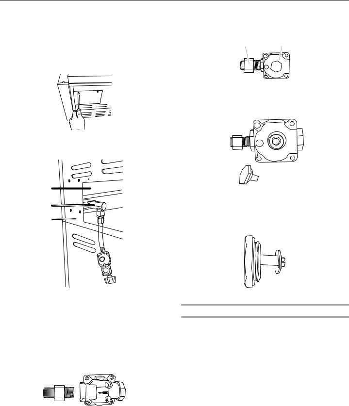
1.Make gas connections.
A combination of pipe fittings must be used to connect the grill to the existing gas line.
■If local codes permit, use an outdoor flexible stainless steel tubing gas connector, design-certified by CSA International, to connect the grill to the rigid gas supply line. A ⁄" diameter line is recommended. Using a wrench to tighten, connect the gas supply to the grill. Use pipejoint compound on all non-flared male threads. Do not kink or damage the flexible connector when moving the grill.
■Pipe-joint compounds suitable for use with LP gas must be used. Do not use TEFLON®† tape.
A
 B
B
C
A.New CSA International approved “outdoor” flexible gas supply line
B.Rear of grill
C.To Natural gas or Local LP gas supply
†®TEFLON is a registered trademark of E.I. Du Pont De Nemours and Company.
2.Open the manual shutoff valve in the gas supply line. The valve is open when the handle is parallel to the gas pipe.
A
B
A.Closed valve
B.Open valve
3.Test all connections by brushing on an approved noncorrosive leak-detection solution. Bubbles will show a leak. Correct any leak found.
4.The batteries are not factory installed. The 1.5-volt “D” size alkaline batteries are located in the accessory box on the grill grate. Install the batteries at this time following the instructions in the “Replacing the Batteries” section.
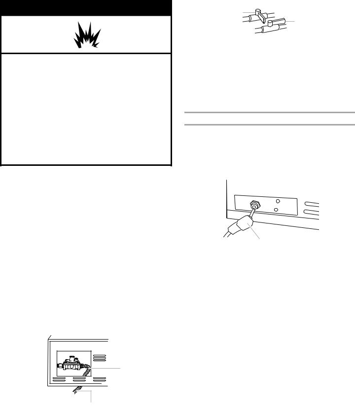
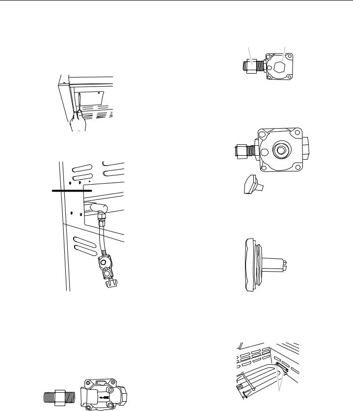
Plug in Grill
NOTE: This built-in outdoor grill comes with a large 5000 mAmp power transformer/plug assembly for the grill’s lights and, on some models, for the electronic display and igniter. Follow the instructions for plugging in and mounting the power transformer. Keep any electrical supply cord away from any heated surfaces.
1.Plug the single-prong plug into the receptacle on the left underside of the grill.
A
A.Single-prong plug
2.Locate or build a non-combustible surface inside the island cabinet to mount the power transformer. It must be to the left side of the grill at a minimum of 3" (7.6 cm) from the side and 4" (10.2 cm) below the bottom of the grill.
3.Mount the power transformer to the mounting surface using 4 #8 screws (not supplied) that are the proper type and length for the transformer and the mounting surface. It must be mounted with the wire for the single-prong plug upward or toward the grill.
NOTE: The cord must be properly mounted with a cord retention device so that its 3-prong plug will not touch the ground when it is unplugged.
17
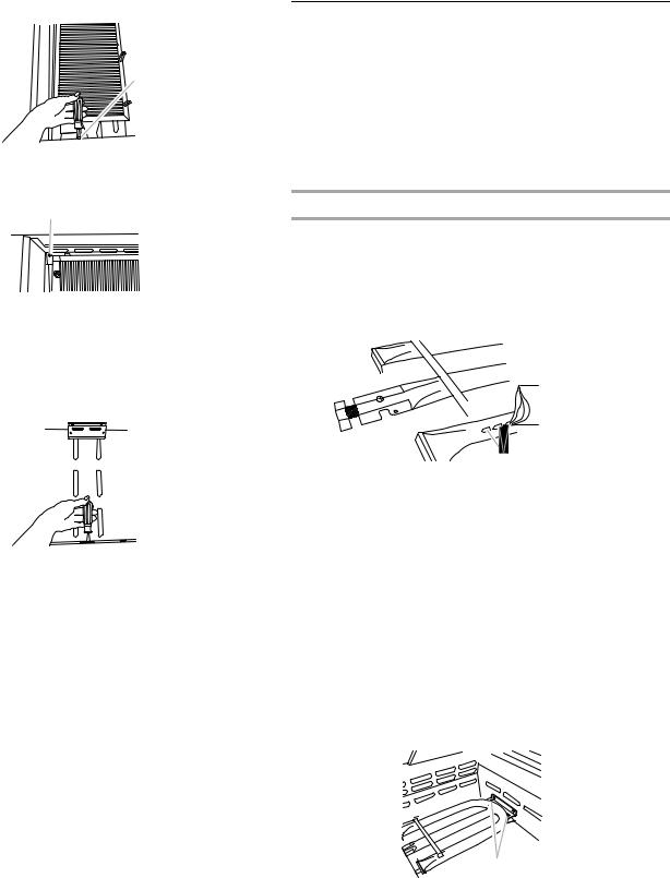
4. Gently slide the grill completely into the outdoor enclosure.
 WARNING
Electrical Shock Hazard
Plug into a grounded 3 prong outlet.
Do not remove ground prong.
Do not use an adapter.
Do not use an extension cord.
Failure to follow these instructions can result in death, fire, or electrical shock.
5.Plug 3-prong power cord plug into a grounded 3-prong GFI outlet.
■To avoid electrical shock, do not immerse cord or plugs in water or other liquid.
■Unplug from the outlet when not in use and before cleaning. Allow to cool before putting on or taking off parts.
■Do not operate any outdoor cooking gas appliance with a damaged cord, damaged plug, or after the appliance malfunctions or has been damaged in any manner. Contact the manufacturer for repair.
■Do not let the cord hang over the edge of a table or touch hot surfaces.
■Do not use an outdoor cooking appliance for purposes other than intended.
■When connecting, first connect plug to the outdoor cooking gas appliance then plug appliance into the outlet.
■Use only a Ground Fault Interrupter (GFI) protected circuit with this outdoor cooking gas appliance.
■Do not remove the ground prong or use with an adapter of 2 prongs.
6.Go to the “Check and Adjust the Burners” section.
GAS CONVERSIONS
ForModelsEquippedforUsewitha20lbLPgasTank
NOTE: Models that are equipped for Natural gas require Gas Conversion Kit Part Number W10118099 for conversion to LP gas. Use the conversion instructions included in the kit. See “Assistance or Service” section for information on ordering.
ToolsandPartsforGasConversion
Gather the required tools and parts before starting installation. Read and follow the instructions provided with any tools listed here.
Tools needed
■ |
Phillips screwdriver |
■ |
10 mm wrench |
■ |
Pipe wrench |
■ |
Thin flat-blade screwdriver |
■ |
Adjustable wrench |
■ |
Pliers |
■ 6 mm socket and wrench |
■ |
Pipe thread sealant |
|
|
or 6 mm nut driver |
|
certified for LP gas |
Parts supplied
■Brass connector
■Convertible regulator 4" W.C. Natural, 11" W.C. LP
■Natural gas orifices
IMPORTANT: Gas conversions must be done by a qualified installer. Before proceeding with conversion, shut off the gas supply to the appliance prior to disconnecting the electrical power.
This kit is designed for use from sea level up to 2000 ft elevation. For higher elevations contact KitchenAid at 1-800-422-1230 in the U.S.A. or call 1-800-607-6777 in Canada.
 WARNING
Explosion Hazard
Use a new CSA International approved “outdoor” gas supply line.
Securely tighten all gas connections.
If connected to LP, have a qualified person make sure gas pressure does not exceed 11” (28 cm) water column.
Examples of a qualified person include:
licensed heating personnel,
authorized gas company personnel, and authorized service personnel.
Failure to do so can result in death, explosion, or fire.
18
ConversiontoaLocalLPGasSupply
Installation of the regulator
1.Turn off the main gas supply valve.
2.Unplug grill or disconnect power.
3.Disconnect 20 lb LP gas fuel tank (if present).
4.Turn off all burner control valves.
5.Remove rear cover and 2 screws.
6.Use adjustable wrench to remove LP hose regulator from brass elbow. Use adjustable wrench to remove brass elbow from shutoff valve.
9.Use pipe wrench to install the convertible regulator. Brass cap will be facing up when tight.
A B
A.Brass connector
B.Convertible regulator
10.To set the appliance regulator for LP gas, use adjustable wrench to remove the brass cap on the convertible regulator.
A 
11. |
Examine the stem on the brass cap. The letters “NAT” should |
B |
be showing on the end of the plastic stem farthest away from |
the brass cap. |
|
12. |
Remove stem from cap, turn it over and snap stem back into |
C |
the cap so the letters “LP” are at the end of the stem farthest |
|
|
|
away from the brass cap. |
LP
D 
A.Manifold
B.Brass elbow
C.Rear of grill
D.Gas pressure regulator/hose assembly
7.Apply pipe sealant to the threads of the brass connector. Use pipe thread sealant that is certified for use with LP gas.
8.Use adjustable wrench to install brass connector (supplied) to shutoff valve.
NOTE: The arrow on the regulator must be pointing toward the brass connector.
13. Use adjustable wrench to reinstall cap onto regulator.
Make Grill Connections
Connect Local LP Gas Supply
1.Use pipe wrench to connect certified ½" (1.3 cm) gas supply pipe to inlet side of regulator from Fixed LP gas supply according to local codes requirements. Use pipe thread sealant that is certified for use with LP gas at connections where required. There must be a certified manual shutoff valve in the gas supply line near the grill for easy access.
2.Turn on the gas supply to the grill.
3.Test all connections by brushing on an approved noncorrosive leak-detection solution. Bubbles will show a leak. Correct any leaks found.
Record Conversion
In the last page of the Use and Care Guide, write “Converted to Local LP Gas Supply.” Also record the conversion date and the technician/company that performed the conversion.
19
ConversionfromLPGastoNaturalGas
Installation of the regulator
1.Turn off the main gas supply valve.
2.Unplug grill or disconnect power.
3.Disconnect 20 lb LP gas fuel tank (if present).
4.Turn off all burner control valves.
5.Remove rear cover and 2 screws.
6.Use adjustable wrench to remove LP hose regulator from brass elbow. Use adjustable wrench to remove brass elbow from shutoff valve.
A 
B 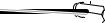

C 
D 
A.Manifold
B.Brass elbow
C.Rear of grill
D.Gas pressure regulator/hose assembly
7.Apply pipe sealant to the threads of the brass connector. Use pipe thread sealant that is certified for use with LP gas.
8.Use adjustable wrench to install brass connector (supplied) to shutoff valve.
NOTE: The arrow on the regulator must be pointing toward the brass connector.
9.Use pipe wrench to install the convertible regulator. Brass cap will be facing up when tight.
A B
A.Brass elbow
B.Convertible regulator
10.To make sure the regulator is set for Natural gas, use adjustable wrench to remove brass cap on appliance regulator.
11.Examine the stem on the brass cap. If the letters “NAT” are not showing on the end of the plastic stem farthest away from the brass cap, remove stem from cap, turn it over and snap stem back into the cap so the letters “NAT” are at the end of the stem farthest away from the brass cap.
NAT
12. Reinstall cap onto convertible regulator.
Change the main grill burner valve orifices
1.Manually remove all of the grates, sear plate, and burners.
2.Remove the 2 screws that hold the burner in place. Remove gas burner from the grill.
A
A. Two screws
20

3.Use 6 mm socket and wrench or 6 mm nut driver to remove the brass orifices from the end of the gas valves.
A
A.Grill burner orifice
4.Install new 2.34 mm orifices supplied with this kit to the end of the gas valve. Use 6 mm socket and wrench or 6 mm nut driver to tighten.
NOTE: The number 2.34 is stamped on the orifice for identification.
A
A.Grill burner orifice
5.Replace burner by sliding the middle tube (venturi) over the orifice.
A
B
A.Burner/orifice connection
B.Burner
6.Reattach gas burner using 2 screws.
A
A.Two screws
7.Repeat the procedure for each grill burner.
Change the Rotisserie-infrared burner orifice(s)
1.Remove the access cover and screw at the back of the grill hood with a Phillips screwdriver.
2.Use Phillips screwdriver to remove 2 screws holding the spider guard to the burner.
A
B
A.Spider guard
B.Two screws
3.Use 10 mm wrench to remove the brass orifice located at the end of the supply pipe.
4.For models with 1 rotisserie burner:
Install 1.9 mm orifice supplied with this kit to the end of the supply pipe. Use 10 mm wrench to tighten.
For models with 2 rotisserie burners:
Install 1.55 mm orifice supplied with the kit to the end of the supply pipe. Use 10 mm wrench to tighten.
NOTE: The number 1.9 mm or 1.55 mm is stamped on the orifice for identification.
5.Replace the spider guard and secure with the 2 screws removed in Step 2.
6.Repeat the procedure for each rear burner.
Change the Sear burner orifices
(for models equipped with sear burner)
1.Remove the sear burner cover screws. Set the screws and cover aside.
A
A
A.Sear burner cover screws
2.Remove the burner igniter mounting screws.
21
3. Loosen the sear burner plate, located next to the igniter.
A
A.Burner igniter mounting screws
4.Remove the sear burner mounting screws.
A
A.Sear burner mounting screws
5.Lift the sear burner out of the grill.
6.Use 6 mm socket wrench or 6 mm nut driver to remove the orifice. Install the new 2.34 mm orifice supplied.
NOTE: The number 2.34 is stamped on the orifice for identification.
7.Reinstall sear burner. Make sure that the igniter is out of the way to allow proper positioning of burner. Use Phillips screwdriver to attach the mounting screws.
8.Use Phillips screwdriver to reattach the igniter and sear burner plate.
9.Reinstall sear burner cover. Use Phillips screwdriver to attach mounting screws.
Hook up to Natural gas and Leak Test
1.Use pipe wrench to connect certified ¹⁄" (1.3 cm) gas supply pipe to inlet side of regulator from Natural gas supply according to local codes requirements. Use pipe thread sealant that is certified for use with LP gas at connections where required. There must be a certified manual shutoff valve in the gas supply line near the grill for easy access.
2.Turn on the gas supply to the grill.
3.Test all connections using an approved noncorrosive leakdetection solution. Bubbles will show a leak. Correct any leak found.
Record Conversion
1.The appliance nameplate is located inside the grill cabinet on the right-hand cabinet side. With a permanent marker, check the box next to “Natural gas” and mark through “LP - Propane.”
In the last page of the Use and Care Guide, write “Converted to Natural Gas.” Also record the conversion date and the technician/company that performed the conversion.
NOTE: Place LP gas parts in plastic parts bag for future use and keep with pack containing literature.
Check andAdjusttheBurners
The burners are tested and factory-set for most efficient operation. However, variations in gas supply and other conditions may make minor adjustments to air shutter or low flame setting necessary.
It is recommended that a qualified person make burner adjustments.
NOTE: The rotisserie burner cannot be adjusted.
Checking and adjusting the grill burner flames requires removing the grate and sear plates.
Burner Flame Characteristics
The flames of the grill burners and side burners (on some models) should be blue and stable with no excessive noise or lifting (LP gas flames will have a slightly yellow tip). A yellow flame indicates not enough air. If flame is noisy or lifts away from the burner, there is too much air. Some yellow tips on flames when the burner is set to HI setting are acceptable as long as no carbon or soot deposits appear.
³⁄" - 1"
(1.9 - 2.5 cm)
on all burner ports with burners on "HI" setting
A
A. Burner ports
Check that burners are not blocked by dirt, debris, insect nests, etc. and clean as necessary. If they are clean, adjust air shutters as needed.
IMPORTANT: Before adjusting air shutters, let burners cool completely.
To Adjust:
1.Light grill using information in the “Outdoor Grill Use” section.
2.Observe flame to determine which burners need adjustment and how the flame is acting.
3.Turn off the valve and wait until grill and burners cool completely.
4.Remove grill grates and sear plates.
5.Remove the 2 screws that hold the burner in place. Remove gas burner from the grill.
A
A. 2 screws
22
6.If flame is yellow (not enough air), turn air shutter adjustment screw counterclockwise.
If flame is noisy or lifts away from burner (too much air), turn air shutter adjustment screw clockwise.
A
A. Air shutter adjustment screw
Adjustment should be made clockwise or counterclockwise from ¹⁄ " (3.2 mm) to ¹⁄ " (6.4 mm).
7.Replace gas burner, sear plates and grates.
8.Light grill using information in the “Outdoor Grill Use” section. See “Burner Flame Characteristics.”
Low Flame Adjustment
If flame goes out on the “LO” setting, the low flame setting must be adjusted.
1.Turn off the valve and wait until grill and burners are cool.
2.Remove grill grates and sear plates.
3.Light grill using information in the “Outdoor Grill Use” section.
4.Turn burner to its lowest setting and remove knob.
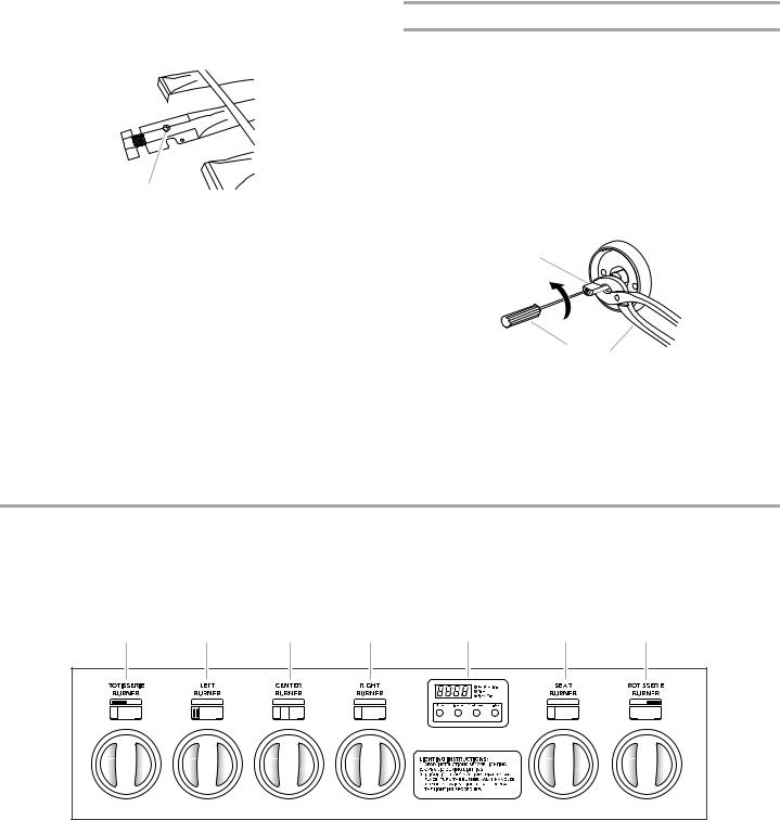
5.Hold valve stem with pliers and insert a small flat-blade screwdriver into the shaft.
6.Watch the flame and slowly turn the screwdriver counterclockwise.
7.Adjust flame to minimum stable flame.
A
B
C
A.Valve stem
B.Small flat-blade screwdriver
C.Pliers
8.Replace the control knob and turn off the burner.
9.Repeat steps 3 through 8 for each burner if needed.
10.Replace the sear plates and grates after the burners have cooled.
OUTDOOR GRILL USE
This manual covers several different models. The grill you have purchased may have some or all of the features listed. The locations and appearances of the features shown here may not match those of your model.
Control Panel
A B C D E F G
A.Left rotisserie burner control knob
B.Left grill burner control knob
C.Center grill burner control knob
|
|
|
|
|
|
|
|
|
|
|
|
|
|
|
|
|
|
|
|
|
|
|
|
|
|
|
|
|
|
|
|
|
|
|
|
|
|
|
|
|
|
|
|
|
|
|
|
|
|
|
|
|
|
|
|
|
|
|
|
|
|
|
|
|
|
|
|
|
|
|
|
|
|
|
|
|
|
|
|
|
|
|
|
|
|
|
|
|
|
D. Right grill burner control knob |
F. Sear burner control knob |
||||||||||||||||
E. Electronic grill display (on some models) |
G. Right rotisserie burner control knob |
||||||||||||||||
Light switch button (on some models) |
|
|
|
|
|
|
|
|
|
|
|
|
|
||||
23
 Loading...