


COMPACT HI-FI SYSTEM
XD-SERIES
XD-A75
XD-A55
INSTRUCTION MANUAL
KENWOOD CORPORATION
This instruction manual is for some models.Model availability and features (functions) may differ depending on the country and sales area.
|
|
|
|
|
|
|
|
|
|
TINSE0365AWZZ |
|
|
|
|
|
|
|
|
|
|
|
B60-5007-00 00 MA (K, P) KW 0010 |
||||||||||
BEFORE APPLYING POWER
 Caution : Read this page carefully to ensure safe operation.
Units are designed for operation as follows.
U.S.A. and Canada........................ |
AC 120 V only |
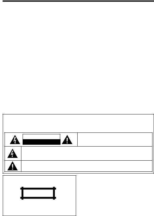
SAFETY PRECAUTIONS
WARNING :TO PREVENT FIRE OR ELECTRIC SHOCK, DO NOT EXPOSE THIS APPLIANCE TO RAIN OR MOISTURE.
CAUTION
RISK OF ELECTRIC SHOCK
DO NOT OPEN
CAUTION: TO REDUCE THE RISK OF ELECTRIC SHOCK, DO NOT REMOVE COVER (OR BACK). NO USERSERVICEABLE PARTS INSIDE. REFER SERVICING TO QUALIFIED SERVICE PERSONNEL.
THE LIGHTNING FLASH WITH ARROWHEAD SYMBOL, WITHIN AN EQUILATERAL TRIANGLE, IS INTENDED TO ALERTTHE USER TOTHE PRESENCE OF UNINSULATED “DANGEROUS VOLTAGE” WITHIN THE PRODUCT’S ENCLOSURE THAT MAY BE OF SUFFICIENT MAGNITUDE TO CONSTITUTE A RISK OF ELECTRIC SHOCK TO PERSONS.
THE EXCLAMATION POINT WITHIN AN EQUILATERAL TRIANGLE IS INTENDED TO ALERT THE USER TO THE PRESENCE OF IMPORTANT OPERATING AND MAINTENANCE (SERVICING) INSTRUCTIONS IN THE LITERATURE ACCOMPANYING THE APPLIANCE.
The marking of products using lasers (Except for some areas)
CLASS 1
LASER PRODUCT
The marking is located on the rear panel and says this product has been classified as Class 1. It means that there is no danger of hazardous radiation outside the product
2 EN
CONTENTS
Page |
Page |
BEFORE APPLYING POWER............................... |
2 |
SAFETY PRECAUTIONS ...................................... |
2 |
ACCESSORIES .................................................... |
3 |
HANDLING OF DISCS AND TAPES ..................... |
4 |
NAMES OF CONTROLS AND INDICATORS |
|
....................................................................... |
5 - 7 |
PREPARATION FOR USE .............................. |
8 - 10 |
SETTING THE CLOCK .................................. |
11 -12 |
SOUND CONTROL ........................................... |
12 |
COMPACT DISC OPERATION ..................... |
13 - 17 |
RADIO OPERATION ................................... |
18 - 20 |
CASSETTE OPERATION .................................... |
21 |
RECORDING (TAPE B only) ........................ |
22 - 23 |
HOW TO USE THE BUILT-IN TIMER ............ |
24 - 26 |
USING EXTERNAL UNITS ................................. |
27 |
RESETTING THE MICROCOMPUTER ............... |
28 |
TRANSPORTING THE UNIT............................... |
28 |
MAINTENANCE ................................................ |
29 |
SPECIFICATIONS ....................................... |
31 - 32 |
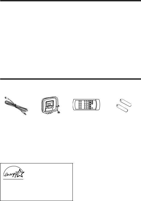
ACCESSORIES
FM Antenna |
AM Loop Antenna |
Remote Control |
“AA” size battery (UM/ |
(1) |
(1) |
(1) |
SUM-3, R6, HP-7 or similar) |
|
|
|
(2) |
As an ENERGY STAR® Partner, Kenwood Corporation has determined that this products meets the ENERGY STAR® guidelines for energy efficiency. This product can save energy. Saving energy reduces air pollution and lowers utility bills.
3 EN
HANDLING OF DISCS AND TAPES
Disc handling precautions
Handling
|
Hold the discs so that you do not |
|
touch the playing surface. |
|
Label side |
|
Playing side |
Sticker |
Do not attach paper or tape to ei- |
|
ther the playing side or the label |
|
side of the discs. |
|
Sticky paste |
Cleaning |
|
|
If fingerprints or foreign matter |
|
become attached to the disc, |
|
lightly wipe the disc with a soft |
|
cotton cloth (or similar) from the |
|
center of the disc outwards in a |
|
radial manner. |
Storage
When a disc is not to be played for a long period of time, remove it from the player and store it in its case.
Discs which can be played with this unit
CD (12 cm, 8 cm) and the audio part of CDV, CD-G, CD-EG and CD-EXTRA. Use discs that comply with the IEC standard, for example a disc carrying the

 marking on the label surface.
Never play a cracked or warped disc
During playback, the disc rotates at high speed in the player. Therefore, to avoid danger, never use a cracked or deformed disc or a disc repaired with tape or adhesive agent. Please do not use discs which are not round because they may cause a malfunction.
Disc accessories
The disc accessories (stabilizer, protection sheet, protection ring, etc.) which are marketed for improving the sound quality or protecting discs as well as the disc cleaner should not be used with this system because they may cause malfunction.
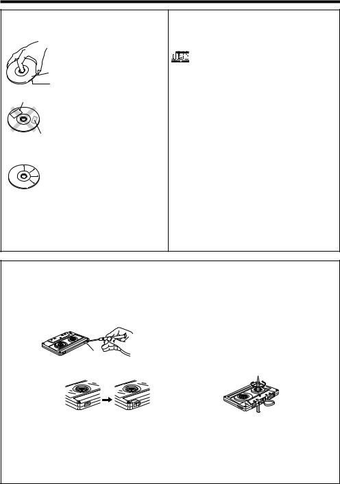
Notes on cassette tape
Safety tab (accidental erasure prevention tab)
After an important recording has been finished, break the safety tab, to prevent the recorded contents from being erased or recorded on accidentally.
To store cassette tapes
Do not store the tapes in a place which is subject to direct sunlight, or near equipment that generates heat. Keep the cassette tapes away from any magnetic field.
When there is slack in the tape
In such a case, insert a pencil into the reel hole
 For A side and wind the reel hub to remove the slack. For B side
To re-record
Apply tape only to the position where the tab has been removed.
Note :
•Do not use an endless tape, as this could damage the mechanism of the unit.
•Do not use a cassette with more than 90 minutes recording time, for the tape used in such a cassette is very thin and tends to cause troubles such as engantlement around the pinch roller or cutting of tape.
4 EN
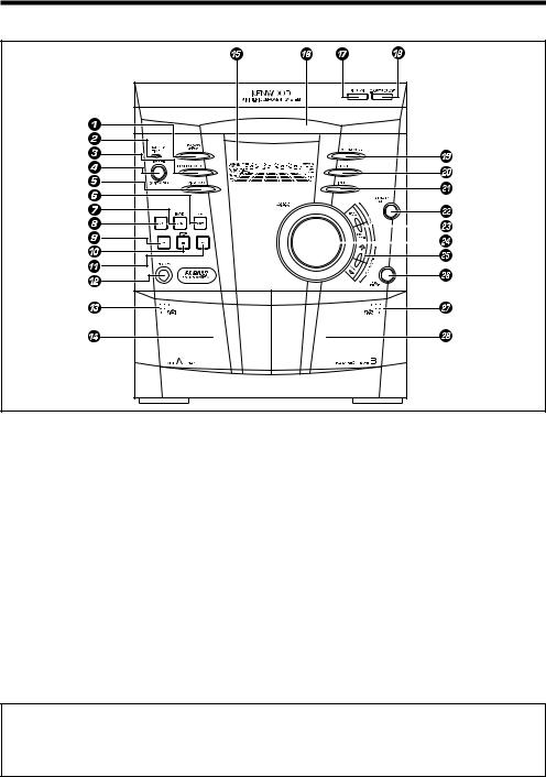
NAMES OF CONTROLS AND INDICATORS
FRONT PANEL
1 EX.BASS / DEMO button |
% Display |
^ Disc tray |
|
2 STANDBY / TIMER indicator |
& DISC SKIP button |
3 REVERSE MODE button |
* 0 OPEN / CLOSE button |
4 POWER / ON / STANDBY button |
( SOUND MODE button |
5 VIDEO / AUX button |
) CLOCK button |
6 TAPE (A/B) button |
¡ TIMER button |
7 TUNER (BAND) button |
™ MEMORY / SET button |
8 CD button |
£ P. CALL (4 1 ¡ ¢) buttons |
9 2 (Reverse play) button |
¢ VOLUME CONTROL knob |
0 7 STOP button |
∞ TUNING / TIME (%UP fiDOWN) buttons |
! 3 (Play / repeat) button |
§ REC PAUSE button |
@ PHONES socket |
¶ PUSH OPEN (Tape B) |
# PUSH OPEN (Tape A) |
• Tape B cassette compartment |
$ Tape A cassette compartment |
|
Standby mode
While the standby indicator of the unit is lit, a small amount of current is flowing into the unit’s internal circuitry to back up the memory. This condition is referred to as the standby mode of the unit. While the unit is in the standby mode, it can be turned ON from the remote control unit.
5 EN

DISPLAY |
|
|
|
34567 890 |
! |
@ |
# |
2 |
|
|
$ |
|
|
% |
|
|
|
|
|
1 |
|
|
|
1 Timer Related Indicator |
9 Tuned Indicator |
2 Disc Number Indicator |
0 Equalizer Indicator |
3 Repeat Indicator |
! Spectrum Analyzer / Volume level Indicator |
4 FM Stereo Mode Indicator |
@ Record Indicator |
5 Play Indicator |
# Extra Bass Indicator |
6 Programme Indicator |
$ Forward / Reverse Play Indicator |
7 Pause Indicator |
% Reverse Mode Indicator |
8 Random Play Indicator |
|
REAR PANEL
1 AC Power Cord
2 FM 75 Ω Antenna Socket
3 AM Loop Antenna Socket
4 Video / Auxiliary (Audio Signal) Input sockets
5 Speaker Terminals
 2 3
2 3
4
1
 5
5
6 EN
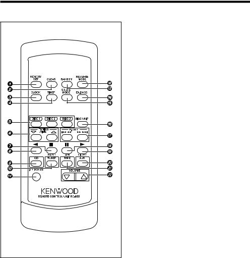
REMOTE CONTROL
1 MEMORY / SET button
2 CLEAR button
3 CLOCK button
4 TIMER button
5 Disc Number Select buttons
6 TUNING / TIME (% fi) buttons
7 7 (Stop) button
8 2 (Reverse Play) button
9 CD button
0 TUNER (BAND) button ! 

 POWER button
@ REVERSE MODE button
# RANDOM button $ EX.BASS button
% SOUND MODE button ^ DISC SKIP button
& P. CALL (4 1 ¡ ¢) buttons * 8 (Pause) button
( 3 (Play / Repeat) button ) VIDEO / AUX button
¡ TAPE (A/B) button ™ VOLUME buttons
7 EN
PREPARATION FOR USE
• Unplug the AC power cord from the AC socket before connecting or disconnecting any component. |
|||
|
|
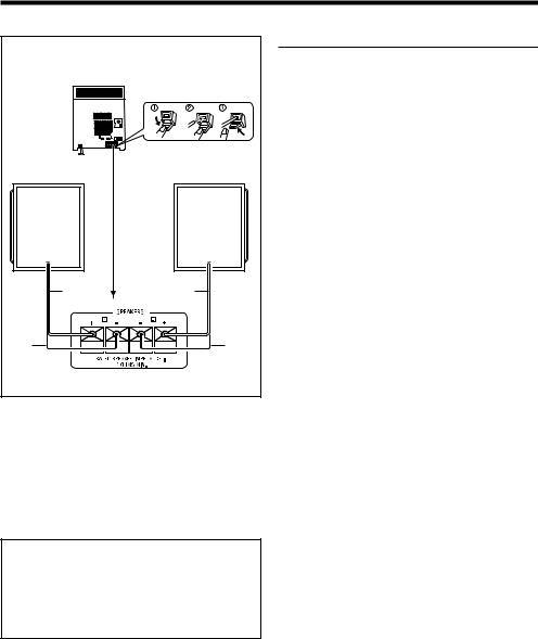
Speaker connection |
|
Speakers (XD-A75, XD-A55) |
Connect each speaker wire to the SPEAKERS ter- |
||
|
|
||
|
|
minals as shown. Use speakers with an impedance |
|
|
|
of 6 ohms or more, as lower impedance speakers |
|
|
|
can damage the unit. |
|
|
|
Connect the black wire to the minus (-) terminal, |
|
|
|
and the red wire to the plus (+) terminal. |
|
Right speaker |
Left speaker |
Caution : |
|
|
|
||
|
|
• Do not mix the right channel and left channel |
|
|
|
wiring when connecting the speakers to the unit. |
|
|
|
The right speaker is the one on the right side |
|
|
|
when you are facing the front of the unit. |
|
|
|
• Do not let bare speaker wires touch each other |
|
Red |
Red |
as this may damage the amplifier and/or speak- |
|
ers. |
|||
|
|
||
|
|
• Do not allow any objects to fall into or to be |
|
Black |
Black |
placed in the bass reflex ducts. |
|
|
|||
|
|
• Do not stand or sit on the speakers. If the speak- |
|
|
|
ers fall or collapse, you may be injured. |
|
System Name |
Speaker Model |
|
Name |
||
|
||
|
|
|
XD-A75 |
LS-N70S |
|
|
|
|
XD-A55 |
LS-N50S |
|
|
|
CAUTION
Be sure to adhere the following, or proper ventilation will be blocked causing damage or fire hazard.
÷Do not place any objects impairing heat radiation onto the top of unit.
8 EN
FM antenna |
AM loop |
|
antenna |
||
|
External FM antenna
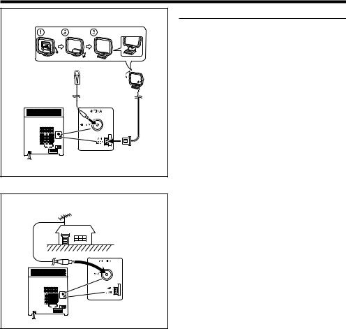
Antenna connection
Supplied FM antenna
Connect the FM antenna wire to the FM 75 Ω terminal and position the FM antenna wire in the direction where the strongest signal can be received.
Supplied AM loop antenna
Connect the AM loop antenna wire to the AM LOOP socket. Position the AM loop antenna for optimum reception.
Place the AM loop antenna on a shelf, etc., or attach it to a stand or a wall with screws (not supplied).
Notes :
•Do not place the antenna on the main unit as it may result in noise pickup from the internal digital electronics.
Place the antenna away from the unit for better reception.
•If the AM loop antenna and the FM antenna wire are placed near to the AC power cord, interference may result.
External FM antenna
Use an external FM antenna if you require better reception.
Consult your dealer.
9 EN
EX.BASS
/DEMO
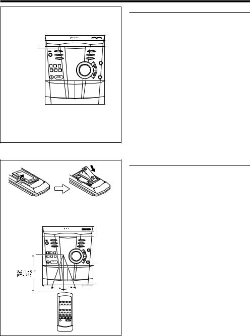
•2 “AA” size batteries (UM/SUM-3, R6, HP-7 or similar)
30 |
30 |
Demo mode
When the AC power cord is first connected, the unit will enter the demonstration mode.
To cancel the demonstration mode :
Press the EX.BASS/DEMO button.
•The demonstration mode will be cancelled and the unit will be in the low power consumption mode.
To return to the demonstration mode :
When the unit is in the standby mode, press the EX.BASS/DEMO button again.
Notes :
•When the unit is in the low power consumption mode, the display will disappear.
•When the power is on, the EX.BASS/DEMO button can be used to select the extra bass mode.
Remote control
•When inserting or removing the batteries, push them towards the  battery terminals.
•Installing the batteries incorrectly may cause the unit to malfunction.
Precautions for battery use :
•Replace all old batteries with new ones at the same time. Do not mix old and new batteries.
•Remove the batteries if the unit will not be used for long periods of time.This will prevent potential damage due to battery leakage.
•Do not use rechargeable batteries (nickelcadmuim battery, etc.)
Note concerning use :
•Replace the batteries if the operating distance is reduced or if the operation becomes erratic.
•Periodically clean the transmitter LED on the remote control and the sensor on the main unit with a soft cloth.
•Exposing the sensor on the main unit to strong light may interfere with operation. Change the lighting or the direction of the unit.
•Keep the remote control away from moisture, excessive heat, shock, and vibrations.
10 EN
 Loading...