


 Loading...
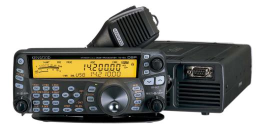
Preface
This in-depth manual for the TS-480 was written by the engineers who actually planned and designed the product. It is our hope that this guide will serve to convey the joys of HF and all the benefits of owning and using the TS-480 to whoever reads this guide – whether you have already purchased a TS-480, an accomplished operator, thinking of buying a transceiver, or just thinking of taking up Amateur Radio as a hobby. We believe the TS-480 will appeal to everyone.
CONTENTS
Design Objectives 2 Development Objectives for the TS-480 Series 5 Circuitry 7 TX circuits 7 RX circuitry 13 Auxiliary Features 19 Features of the Built-in DSP 21 Tips 28 Structural Features 36 New Option: Voice Guide & Storage Unit (VGS-1) 42 New Option: ARCP-480 (Freeware) 45 New Option: ARHP-10 (Freeware) 51
TS-480HX TS-480SAT
200W output
(HF: 200W 50MHz: 100W)
100W output (HF: 100W 50MHz: 100W built-in automatic antenna tuner)
2

 Design Objectives
Determination to create a unique transceiver
The concept of a compact HF transceiver first saw the light of day with Kenwood’s TS-50. From then on, such equipment has become an essential part of the Amateur Radio world. Equipment has now evolved with the appearance of multi-band models.
In developing this new HF transceiver, Kenwood has boldly chosen not to follow this path, because we wanted to develop a transceiver unlike any other available. If we had developed a product along the same lines as the others currently in the market, the customers would not have found it a very attractive buy and few would choose it. This is why we wanted to develop a unique and attractive Kenwood product, something that would effectively serve to create a new market.
It was with these thoughts that we embarked on our new project and began to mull over the details.
It was not to be an easy task. After all, every engineer involved in development wants to create something special and innovative. We had to find a way to put it into practice.
Back to basics: “The appeal of HF lies in DX’ing.”
The search for “a completely new kind of transceiver” sounds like it might turn out to be a wild goose chase, and in truth it is in the nature of things that such ideas rarely amount to much. But as part of our brainstorming, we went back to basics. What first emerged as a key concept was this: “The appeal of HF lies in DX’ing.” This is simple to say, but maybe more difficult to realize. From here the discussion moved ahead rapidly once it was decided to develop a compact HF transceiver.
According to conventional wisdom, a compact HF transceiver is by definition a mobile transceiver, and a fixed, base station is physically large. But we refused to stick to these stereotypes as we fleshed out the concept for a compact HF transceiver designed to make DX’ing really enjoyable.
Even if it were to be a mobile unit, as an HF transceiver we wanted to ensure it would offer the operating ease and basic performance needed to enjoy DX’ing.
Consequently, it should also be able to serve as a fixed station.
The typical shack today has been equipped with a computer and there is not a great deal of room available for a large transceiver. This PC-transceiver combination would become even more common.
Operating both as a mobile and as a fixed station, this new model would target customers dissatisfied with the compact transceivers currently on the market.
This was the concept that we started with.
3
Standalone control panel
For mobile operations, a separate control panel is ideal, but what if the transceiver is also to be used as a base station? This was the problem we faced. With a large desktop rig, it is no easy matter to shift things around to find the best position, so perhaps it would be a good idea to have a separate control panel that could be moved easily. Also, a desktop unit has various kinds of cables connected to it. What with the heat the main unit produces and the noise of the fan, etc., and considering that it does not have to be on the desk in front of you, it would surely be better to separate the control panel and place the main unit elsewhere.
With the appearance of computers in today’s shacks, it is certainly desirable to tidy up the desktop as much as possible. We felt that we could contribute to this evolutionary process. By opting for a completely separate panel, we could ensure that it would be large enough to offer sufficient operating ease, since its dimensions would not be dictated by those of the compact main unit. This was how we arrived at the idea of a standalone control panel that is slightly larger than the main unit.
Focus on basic performance
The appeal of HF lies in DX’ing those places near and far. For this reason, we put a priority on operating ease and basic performance. At this point the project team had already excluded any idea of incorporating the V/UHF bands. Our approach was this: “Rather than spending development money on the V/UHF bands, let’s spend money on HF performance.” “If someone needs the V/UHF bands, then they can buy another product that is tailored for these bands.” This meant we had confidence that our product would offer more than enough punch to perform well even on grueling DX’peditions.
The 200W challenge
As explained, our initial starting point was a desire to create a transceiver like no other. But we would not have succeeded in meeting this objective with just a standalone control panel and an emphasis on basic performance. We needed something more if we were to make the product truly special and stand out from the crowd.
The answer was to be found in the realization that DX operations depend on basic performance and power. Real “power” in a transceiver is something that many people look for. So a radical proposal was made: “Rather than making the output 100 watts, let’s go all out for 200 watts!” But in fact the only transceivers on the market with 200W output were the expensive high-end models. What we were developing was a compact transceiver.
We seemed to have run up against a wall: Did this mean that in terms of size and cost we would inevitably end up creating a high-end transceiver? After long discussions, we made a straightforward decision to challenge the status quo: If conventional wisdom dictated that a 200W output was only available from a high-end transceiver, then we would change that dynamic.
At this point we could not see how this could be possible, but we stuck to our conviction that a 200W transceiver did not have to be expensive. We were determined to provide the customer with a 200W transceiver at a reasonable price. As a result of our single-mindedness, we were eventually able to achieve our goal, creating a product of about the same size as the TS-50 and, of course, it had heavy-duty specs.
4
Adding appeal to fixed station operations
It is now increasingly common to see a PC sitting beside the transceiver in the shack, but we wanted to expand the interaction between computers and transceivers. It was with this in mind that
Kenwood came up with the idea of an Internet remote-controlled transceiver. You may be away on a business trip, but you want to operate, or you may want to use a large Yagi antenna out in the suburbs from your downtown apartment. In these and many other ways, fixed station operations are becoming more varied and more difficult. However, laws governing radio transmissions vary from country to country. In Japan, we had just about resigned ourselves to the fact that this could only be implemented as an RX feature when fortunately the law changed: starting January 13, 2004, both TX and RX operations became possible. This made all our development work worthwhile for our market in Japan and worldwide.
Overview of the TS-480 Series
The product concept for the TS-480 Series, as outlined, can be summarized thus:
Not simply a compact HF mobile transceiver like the TS-50 and other transceivers on the market, the TS-480 is a completely new type of powerful compact HF transceiver offering the performance and features required for HF DX operations.
TX output of 200W (HF), an astounding figure; and up till now, only available from the top-of-the-line models.
Transceiver remote control
In order to realize all three of these, we started the design process with the following planning objectives:
1.Priority on basic performance that stresses the 1.8 ~ 50 MHz range;
2.Dynamic range on a par with the TS-950;
3.Uncompromising RX performance, AF DSP as standard;
4.A control panel design that ensures top-notch operating ease, so that desired functions can be accessed instantly;
5.Support for a range of different operations as a mobile station and as a full-fledged base station, allowing the user to enjoy HF DX as much as with a conventional fixed station;
6.A quantum leap in power output in a compact chassis, generating 200W even when working off a DC 13.8V supply (in the USA there are no limitations on the power output of mobile transceivers, so it is being described as a “power mobile”);
7.Internal automatic tuner for the 100W model to make it more versatile and expand the range of possible applications; and
8.Remote control via the Internet.
As for the name of the new series, which was intended to reflect our planning objectives, we decided on the 400’s in order to express continuity with the popular TS-450 workhorse transceiver.
This was because the new product was not simply a compact transceiver but would offer the sort of performance and features Kenwood fans would expect of a 400-series model. A workhorse transceiver that could prove its worth in a variety of places – in the shack, in a vehicle, in the field -- this was the TS-480 Series being planned by Kenwood.
5


 Development Objectives for the TS-480 Series
The following is an explanation of our development objectives, distinct from the planning objectives.
If asked about the origins of the compact HF rig, people outside Japan would no doubt think of the Atlas Series. Following the Atlas, a variety of different products appeared on the market, but it is probably no exaggeration to say that Kenwood’s TS-50 was the first in the category of the 100W (HF) compact all-mode transceiver. It is already more than a decade since the TS-50 was launched. Since then, successive models have grown increasingly smaller while adding new features and expanding band coverage to include V/UHF. Today, this category has matured to the point of actually forming a definable market. What we developed in order to stir up and add fresh stimulus to this market was the TS-480 Series.
•Why a compact 200W transceiver?
•Why a 100W model with a built-in antenna tuner?
•Why HF~50MHz coverage?
The answers to these questions can be found in our planning objectives. Let’s look at the technical background.
The TS-480 concept began with development of the TS-570?
We first started looking in detail at the technical feasibility not of the 200W model but of the model with the internal antenna tuner. Today, there is nothing special about a built-in AT, but for the TS-570 we developed a relay-type AT. This replaced the previous motor-driven variable capacitor type of AT. Naturally this technology was used elsewhere and by other manufacturers, but if applied not to TX but to RX also, it is possible to use it for receiver front-end passive tuning. For transmission purposes, it is smaller than the conventional type of AT of the time, especially with regard to height, making it a good choice for building into a compact set.
In 1996, when on a visit to the US to promote the TS-570 a local salesman asked whether we were next going to put an AT into the TS-50. Well, perhaps that was where the TS-480 got its start!
Achieving 200W output in a compact transceiver
In achieving our goal of 200W there was one major constraint – namely, we could not raise the voltage of the power supply. The TS-480 Series was to be sold not only in Japan but internationally. If we had been looking only at our domestic market, things would have been different since the output of mobile transceivers here is limited to 50W, but conditions are different abroad, especially in the US. In the US, since there are no limitations on the output of either mobile or fixed stations, mobile transceivers in the several hundred watt class are not unusual. A common pattern for operations is not to hook up a 100W unit to a linear amp and mount a 200W fixed transceiver in a car. Moreover, the most common type of vehicle is a pickup with a 12V battery, so people expect to obtain a 200W output with a regular 13.8V power supply.
If one thinks of the way people operate such transceivers here in Japan, a question arises: Why add that much power if it cannot be used as a mobile rig? The TS-480 has been designed with a priority on operating ease. One reason for this is that we saw the TS-480 being used as a fixed station in Japan, where 200W mobile operations are not permitted. Most 200W HF transceivers are high-end and their price reflects this. But in the workhorse class, most models offer only 100W output. So we can say that our new product can fulfill the wishes of those who have received an advanced permit and thus want a 200W rig – as long as it is not expensive.
6
Focusing on HF
Raising power output and adding an antenna tuner are both moves in the right direction, but limiting the transceiver to the HF bands when the mainstream nowadays is HF~V/UHF would seem to be going against the tide of the times. Yet opting for the multi-band route inevitably leads to larger dimensions and higher prices. In this genre, price is an important factor, so by limiting the
TS-480 to HF, we developed what is in fact a compact transceiver that stands apart from the competition. The TS-480 is designed to ensure not only excellent TX performance but also superior RX performance.
7


 Circuitry
● TX circuits
200W final section
Explained here is the circuitry for the 200W final section, the crown jewel of the TS-480 Series. This circuit is responsible for developing 200W output with a DC 13.8V power supply. Of course, various approaches are possible. The typical one would be to use a high voltage (28V or more) with the FETs in a push-pull arrangement. However, we did not adopt this approach since a
DC-DC combination that raises the voltage to 28V exclusively for this purpose was considered inappropriate for a compact rig. The final section of a regular transceiver delivers 100W from 13.8V, so the normal approach would be to use this as the basis for a 200W design. Hence, we considered the pros and cons of using 4 final devices, each with 50W output, to produce a total of
200W.
I will not go into details here, but following our calculations and tests we discovered that simply hooking up the devices in parallel would not be a practical solution because of issues related to the output transformer. The solution we finally adopted was to have a pair of 100W final sections with a standard push-pull arrangement, combining these to obtain an output of 200W. Since this is the most popular method, we should perhaps have adopted it from the start, but having no past experience with a transceiver producing 200W from a 13.8V supply, we looked at the design issues from various angles including performance, quality, size, cost, and manufacturability.
When one simply says “combine”, there are in fact different ways to do this. For example, you can take a pair of 100W final circuits and connect in series the secondary circuit of the output transformer in phase to double the output, thus producing 200W. When we actually experimented with this, we found that it worked okay. Frequency characteristics were good. However, using this method means that one cannot provide isolation between the amplifiers. So what we finally adopted was the old standby in situations like this – namely, a wideband hybrid combiner.
The circuit for this combiner is straightforward: if you reverse the input and output it will actually work as a splitter. For the TS-480HX, we put together a 200W output final circuit by using this type of combiner on the input/output of a pair of 100W final amplifiers. For the 50MHz band, we have limited the output to 100W because of the heat that we knew would be generated from loss.
A hybrid combiner only works on the condition that the two signals are identical in amplitude and phase. Since our final section was to operate in the HF~50MHz bands, it would qualify as wideband in terms of frequency but there would be some concern for the balance frequency characteristics. However, this sort of power combiner has been used before for general applications, so in that sense it is an approach that can be adopted with some confidence.
When it came to the actual design (mounting), an ideal, symmetrical layout of the components was not possible; however, care was taken to preserve the balance, for example by employing isometric wiring for patterns in which there are many high-frequency currents flowing.
The device used was the 2SC2782 bipolar transistor. Since this has a collector loss of 220W, there would a total loss of 880W in a 200W set equipped with four of them; this represents more than enough leeway for operations.
Continuous transmission performance with such a compact design is explained in the section on the TS-480 structure.
8
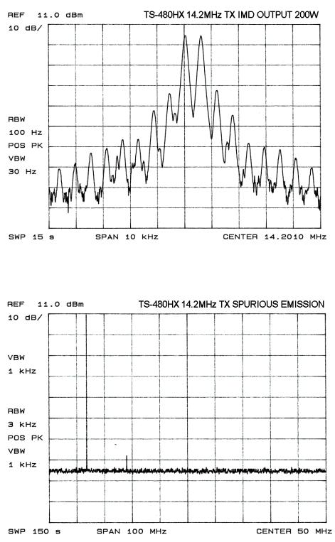
Fig. 1 illustrates TX IM characteristics with 200W output at 14MHz, while the second graph (Fig. 2) charts high-frequency spurious emissions.
Fig. 1: TX IMD (output 200W)
Fig. 2: TX Spurious emissions
9
SPS (separate power sources) [TS-480HX only]
SPS is shorthand for “operating at 200W using two 100W 13.8V power sources.” To generate a 200W output from 13.8V requires a maximum (total) current of 41A. As previously explained, the
TS-480HX employs a pair of 100W final amps. What the SPS design does is to supply these amps from two separate power supplies, as shown in Fig. 3 below.
The use of two power supplies may appear inconvenient, but in actual fact this arrangement is quite practical. Many customers already possess a 100W class power supply, so when they acquire this 200W transceiver they do not have to make an additional purchase of a new 200W class power supply. It is possible for them to make use of the 100W unit in their possession.
The PS-53 power supply is specified for the TS-480; however, as long as it can produce 20.5A or more continuously at 13.8V, other power supplies can be used. Also, it is possible to operate this transceiver using a single power supply that can produce at least 41A continuously; note, however, that two power cables would still be needed.
Fig. 3: SPS schematic diagram
|
|
|
|
|
|
|
|
|
|
|
|
|
|
|
|
|
|
|
|
|
|
|
|
|
|
|
|
|
|
|
|
|
|
|
|
|
|
|
|
|
|
|
|
|
|
|
|
|
|
|
|
|
|
|
DC1 connector |
|
|
|
|||
|
|
|
|
|
|
|
|
|
|
|
|
|
|
|
|
|
|
|
|
|
|
|
|
|
|
|
|
|
|
|
|
|
|
|
|
|
|
|
|
|
|
|
|
|
|
|
|
|
|
|
|
|
|
|
|
|
|||||
|
|
|
|
|
|
|
|
|
|
|
|
|
|
|
|
|
|
|
|
|
|
|
|
|
|
|
|
|
|
|
|
|
|
|
|
|
|
|
|
|
|
|
|
|
|
|
|
|
|
|
|
|
|
|
|
|
|
|
|
|
|
|
|
|
|
|
|
|
|
|
|
|
|
|
|
|
|
|
|
|
|
|
|
|
|
|
|
|
|
|
|
|
|
|
|
|
|
|
|
|
|
|
|
|
|
|
|
|
|
|
|
|
|
|
|
|
|
|
|
|
|
|
|
|
|
|
|
|
|
|
|
|
|
|
|
|
|
|
|
|
|
|
|
|
|
|
|
|
|
|
|
|
|
|
|
|
|
|
|
|
|
|
|
|
|
|
|
|
|
|
|
|
|
|
|
|
|
|
|
|
|
|
|
|
|
|
|
|
|
|
|
|
|
|
|
|
|
|
|
|
|
|
|
|
|
|
|
|
|
|
|
|
|
|
|
|
|
|
|
|
|
|
|
|
|
|
|
|
|
|
|
|
|
|
|
|
|
|
|
|
|
|
|
|
|
|
|
|
|
|
|
|
|
|
|
|
|
|
|
|
|
|
|
|
|
|
|
|
|
|
|
|
|
|
|
|
|
|
|
|
|
|
|
|
|
|
|
|
|
|
|
|
|
|
|
|
|
|
|
|
|
|
|
|
|
|
|
|
|
|
|
|
|
|
|
|
|
|
|
|
|
|
|
|
|
|
|
|
|
|
|
|
|
|
|
|
|
|
|
|
|
|
|
|
|
|
|
|
|
|
|
|
|
|
|
|
|
|
|
|
|
|
|
|
|
|
|
|
|
DC power |
|
|
|
|
|
|
|
|
|
|
|
|
|
|
|
|
|
|
|
|
|
|
|
|
|
|
|
|
|
|
|
|
|
|
|
|
|
|
|
|
|
|
|
|
|
|
|
|
|
|
|
|
|
|
|
|
|
|
|
|
|
||
|
|
|
|
|
|
|
|
|
|
|
|
|
|
|
|
|
|
|
|
|
|
|
|
|
|
|
|
|
|
Drive amp |
|
|
|
|
|
|
|
|
|
|
|
|
|
|
|
|
|||||||||||||||
|
|
|
|
|
|
|
|
|
|
|
|
|
|
|
|
|
|
|
|
|
|
|
|
|
|
|
|
|
|
|
|
|
|
|
|
supply 1 |
|||||||||||||||||||||||||
|
|
|
|
|
|
|
|
|
|
|
|
|
|
|
|
|
|
|
|
|
|
|
|
|
|
|
|
|
|
|
|
|
|
|
|
Final amp 1 |
|
|
|||||||||||||||||||||||
|
|
|
|
Other circuits |
|
|
|
|
|
|
|
|
|
|
|
|
|
|
|
|
|
|
|
|
|
|
|
|
|
|
|
|
|
|
|
|
|
|
|
(13.8V, ≥20.5A) |
|||||||||||||||||||||
|
|
|
|
|
|
|
|
|
|
|
|
|
|
|
|
|
|
|
|
|
|
|
|
|
|
|
|
|
|
|
|
|
|
|
|
|
|
|
|
|
|
|
|
||||||||||||||||||
|
|
|
|
|
|
|
|
|
|
|
|
|
|
|
|
|
|
|
|
|
|
|
|
|
|
|
|
|
|
|
|
|
|
|
|
|
|
|
|
|
|
|
|
|
|
|
|
|
|
|
|
|
|
|
|
|
|
|
|
|
|
|
|
|
|
|
|
|
|
|
|
|
|
|
|
|
|
|
|
|
|
|
|
|
|
|
|
|
|
|
|
|
|
|
|
|
|
|
|
|
|
|
|
|
|
|
|
|
|
|
|
|
|
|
|
|
|
|
|
|
|
|
|
|
|
|
|
|
|
|
|
|
|
|
|
|
|
|
|
|
|
|
|
|
|
|
|
|
|
|
|
|
|
|
|
|
|
|
|
|
|
|
|
|
|
|
|
|
|
|
|
|
|
|
|
|
|
|
|
|
|
|
|
|
|
|
|
|
|
|
|
|
|
|
|
|
|
|
|
|
|
|
|
|
|
|
|
|
|
|
|
|
|
|
|
|
|
|
|
|
|
|
|
|
|
|
|
|
|
|
|
|
|
|
|
|
|
|
|
|
Final amp 2 |
|
|
DC power |
|||
|
|
|
|
|
|
|
|
|
|
|
|
|
|
|
|
|
|
|
|
|
|
|
|
|
|
|
|
|
|
|
|
|
|
|
|
|
|
|
|
|
|
|
|
|
|
|
|
|
|
|
|
|
|
|
|||||||
|
|
|
|
|
|
|
|
|
|
|
|
|
|
|
|
|
|
|
|
|
|
|
|
|
|
|
|
|
|
|
|
|
|
|
|
|
|
|
|
|
|
|
|
|
|
|
|
|
|
|
|
|
|
|
|
|
|
|
|
supply 2 |
|
|
|
|
|
|
|
|
|
|
|
|
|
|
|
|
|
|
|
|
|
|
|
|
|
|
|
|
|
|
|
|
|
|
|
|
|
|
|
|
|
|
|
|
|
|
|
|
|
|
|
|
|
|
|
|
|
|
|
|
|
||
|
|
|
|
|
|
|
|
|
|
|
|
|
|
|
|
|
|
|
|
|
|
|
|
|
|
|
|
|
|
|
|
|
|
|
|
|
|
|
|
|
|
|
|
|
|
|
|
|
|
|
|
|
|
|
|
|
|
|
|
||
|
|
|
|
|
|
|
|
|
|
|
|
|
|
|
|
|
|
|
|
|
|
|
|
|
|
|
|
|
|
|
|
|
|
|
|
|
|
|
|
|
|
|
|
|
|
|
|
|
|
|
|
|
|
|
|
|
|
|
|
(13.8V, ≥20.5A) |
|
|
|
|
|
|
|
|
|
|
|
|
|
|
|
|
|
|
|
|
|
|
|
|
|
|
|
|
|
|
|
|
|
|
|
|
|
|
|
|
|
|
|
|
|
|
|
|
|
|
|
|
|
|
|
|
|
|
|
|
|
||
|
|
|
|
|
|
|
|
|
|
|
|
|
|
|
|
|
|
|
|
|
|
|
|
|
|
|
|
|
|
|
|
|
|
|
|
|
|
|
|
|
|
|
|
|
|
|
|
|
|
|
|
|
|
|
|
|
|
|
|
||
|
|
|
|
|
|
|
|
|
|
|
|
|
|
|
|
|
|
|
|
|
|
|
|
|
|
|
|
|
|
|
|
|
|
|
|
|
|
|
|
|
|
|
|
|
|
|
|
|
|
|
|
|
|
|
|
|
|
|
|
|
|
|
|
|
|
|
|
|
|
|
|
|
|
|
|
|
|
|
|
|
|
|
|
|
|
|
|
|
|
|
|
|
|
|
|
|
|
|
|
|
|
|
|
|
|
|
|
|
|
|
|
|
|
|
|
|
|
|
|
|
|
|
|
|
|
|
|
|
|
|
|
|
|
|
|
|
|
|
|
|
|
|
|
|
|
|
|
|
|
|
|
|
|
|
|
|
|
|
|
|
|
|
|
|
|
|
|
|
|
|
|
|
|
|
|
|
|
|
|
|
|
|
|
|
|
|
|
|
|
|
|
|
Chassis |
|
|
|
|
|
|
|
|
|
|
|
|
|
|
|
|
|
|
|
|
|
|
|
|
|
|
|
|
|
|
|
|
|
|
DC2 connector |
|
|
|
||||||||||||||||
|
|
|
|
|
|
|
|
|
|
|
|
|
|
|
|
|
|
|
|
|
|
|
|
|
|
|
|
|
|
|
|
|
|
|
|
|
|
|
|
|
|
|
|
|
|
|
|
|
|
|
|
|
|
|
|
|
|
|
|
|
|
|
|
|
|
|
|
|
|
|
|
|
|
|
|
|
|
|
|
|
|
|
|
|
|
|
|
|
|
|
|
|
|
|
|
|
|
|
|
|
|
|
|
|
|
|
|
|
|
|
|
|
|
|
|
|
|
|
|
|
|
|
|
10
Failsafe device (some TS-480HX versions only)
The use of two power supplies and two final amps in parallel is something that has not been tried before, and naturally there may be some anxiety on the part of the user regarding what would happen if just one of the power supplies suddenly failed. Such a situation would be handled safely, since the TS-480 series is equipped with several failsafe devices.
Should a difference of 1V or more be detected between the two power supplies: “RX ONLY” appears in the display and transmission operations are inhibited.
Should the voltage of one power supply drop to zero: if the failed supply is DC1 (Fig. 3), the transceiver is powered down; if DC2 fails, “RX ONLY” appears in the display and only RX operations are possible.
Should a final amp malfunction: if, for example, the output of one of the final amps fell, resulting in an imbalance, “PA-ERROR” appears in the display and transmission operations are terminated.
In addition, there is the usual complement of failsafe devices, including output control triggered by high temperature, high voltage detection, and SWR output control. These failsafe devices will provide temporary protection for the internal circuitry; however, should such a situation arise you should not continue using the transceiver, but rather deal with the problem in accordance with the troubleshooting guidelines.
100W final section
Like the 200W final section, the 100W final section uses 2SC2782 transistors. The drive and peripheral circuits are virtually identical to those in the 200W model, enabling 100W output for the HF~50MHz bands.
For the Japanese market, there are 50W and 10W (50MHz: 20W) models, allowing buyers to choose whichever best suits them – that is, their license and their intended use (mobile or fixed).
It should be pointed out that it is possible to increase the output of these models: the 50W model to
100W, and the 10W model to 50W or 100W. A TS-480 owner who acquires a more advanced license and wants to make use of this capability should go to the nearest service center. Note that it is not possible to upgrade to 200W output.
Also, 50W mobile transceiver warranty certification is available for both 200W and 100W models used as fixed stations.
Ever since the TS-570, Kenwood has adopted a method of converting transceivers to higher output specifications that does not require a kit. Conversion cannot be performed by the individual user, but because this method does not depend on finding stock of the appropriate kit it is proving popular.
Antenna tuner (TS-480SAT)
The 100W model is equipped with the relay-driven antenna tuner that was developed for the TS-570. Since there is no variable capacitor, gears or other rotating parts, this antenna tuner is very responsive and trouble-free. Thanks also to the several preset memories supplied for each band, you can instantly call up settings when moving up or down a band.
You can see the 200W and 100W final sections in Figs. 4 and 5, respectively.
11

Fig. 4: 200W final section
Fig. 5: 100W final section with antenna tuner
12
FM circuit
There were two approaches used for the FM circuit of the conventional all-mode transceiver. Either there was a dedicated modulation circuit using a 10.695MHz crystal, or the modulation was performed by the VCO on the 2nd OSC. The latter was not an option for the TS-480, and since the whole transceiver had to be compact, we did not adopt the former approach. How then is FM handled by the TS-480?
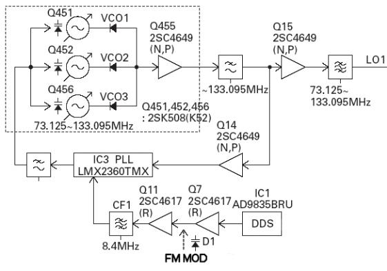
What we have employed for the TS-480 is something that is rarely seen these days in ham radios: the reactance modulation approach, which does not have the modulation applied directly to the oscillating circuit. This type of circuit was widely used in the days when a crystal was used to change channels in FM car transceivers, but it dropped from sight when PLL became the norm. It is not a new circuit, but it has excellent characteristics. In the TS-480, this reactance modulation circuit is connected to the output of the DDS, which serves as the source for the PLL reference frequency, so effectively it is modulating the 1st OSC.
This approach offers several advantages:
Since frequency modulation is not conducted in the TX signal circuitry, even if the TX RF signal is passed through a roofing filter, it will not suffer from any delay distortion caused by the filter; Since there is no need for an oscillator to perform modulation, “one-shot“ frequency management is permitted when transmitting on FM with the same precision as SSB;
This approach saves on space and cost.
Fig. 6: FM modulation block diagram
13
● RX circuitry
Front end
As explained in the section on development objectives, what distinguishes the TS-480 Series are incomparable features and performance that result from our focus on HF. Of special note are the dynamic range characteristics in the HF bands, demonstrating the fact that, despite the compact dimensions of this transceiver, there has been no design compromise.
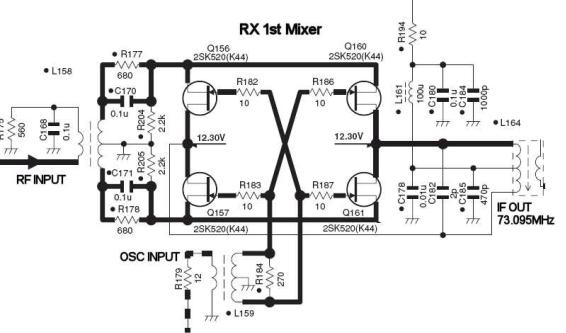
One of the circuits that is important in determining dynamic range is the first mixer. Now there are some compact transceivers covering HF~V/UHF that are designed to cover all frequency bands with a single mixer. Since HF~50MHz is the “home turf” for the TS-480 Series, it has an advantage as in regards to the operating conditions for the mixer. Since developing the TS-950, Kenwood has exclusively employed J-FET quad mixers, and the TS-480 is no exception. Fig.7 illustrates the mixer circuit.
Fig. 7: RX 1st mixer
14
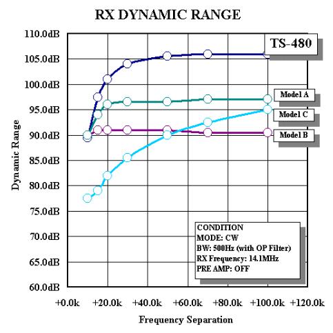
How well does it actually perform? Fig. 8 is a graph illustrating the dynamic range characteristics when changing the separation of two interfering signals. For the sake of reference, results for the
TS-480 are plotted against those obtained using other compact mobile transceivers (on the market) under the same conditions.
Fig. 8: RX dynamic range
Looking at Fig. 8, results higher up the graph indicate wider dynamic range.
When the RX frequency is 14.100MHz, and for example there is simultaneous interference from two signals at 14.150MHz and 14.200MHz, with the nonlinearity of the RX section, spurious signals are generated at 14.100MHz and 14.250MHZ, enabling reception. Since the frequency separation at this point is 14.200MHz -14.150MHz = 50kHz, the +50.0KHz point on the horizontal axis of Fig. 8 corresponds to these conditions. Under these conditions, if there were interfering signals that were faintly picked up by the other transceivers in this comparison, the strength of those interfering signals would have to rise by 10~15dB for the TS-480 to begin suffering the same effects.
When there is interference in close proximity to the RX frequency, there is no difference between these models, with one notable exception. In this area we are approaching the bandwidth of the roofing filter, so to put it another way, the fact that we can observe a difference between the transceivers at the +50kHz point – where the interference is sufficiently eliminated by the roofing
15
filter – reflects a difference in the manufacturers’ approach to design from the antenna to the 1st mixer.
It is not just the mixer that determines the characteristics of the front end: all of the components between the antenna terminal and the mixer can have an impact.
Despite the compact design of the TS-480 Series, its RX BPF divides up the 500kHz~60MHz range into 10 bandwidths. Since several coils are employed in this BPF circuit, small coils have to be used in a compact transceiver. When discussing front end linearity, attention focuses on semiconductors such as the PIN diode for switching bands, but in fact the coils used in this BPF can be “nonlinear” parts, depending on operating conditions. Differences in their characteristics become more noticeable the smaller they are. In the early stages of developing the TS-480, we looked at the mutual modulation characteristics of a number of coils, picking only those that demonstrated the best performance.
With this compact transceiver it was not possible to use a passive tuner equivalent to what is found in top-end models, but our emphasis on HF performance was such that we selected components whose advantage cannot even be appreciated from a circuit diagram.
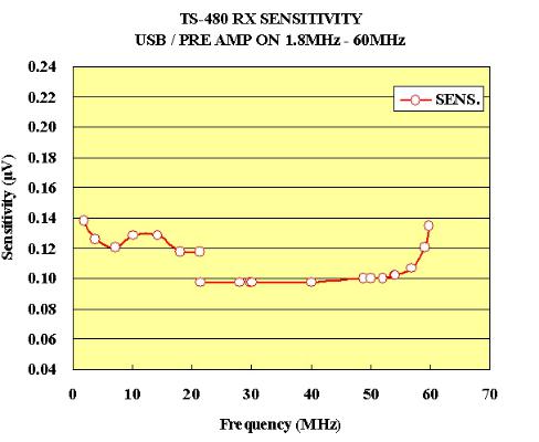
Fig. 9 is a graph demonstrating RX sensitivity. Needless to say, for HF, especially in the low bands, there is more importance attached to multi-signal characteristics than to sensitivity, but obtaining a sufficient level of sensitivity can be vital during mobile operations when one cannot expect much in the way of antenna gain.
As with previous models, sensitivity is set to switch at 21.5MHz with the pre-amp on. However, there is a difference: previously the pre-amp itself was switched, but in the case of the TS-480 this is managed by switching the pre-amp’s NFB gain.
Fig. 9: RX sensitivity
16
 Jumpers for joy
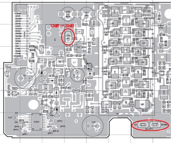
As with the TS-2000, something special has been provided for both the BPF ATT in the BC band and the regular ATT:
The BPF has been equipped with an ATT in order to cope with powerful local broadcasting stations in the BC band. However, a jumper can be used to switch from NORM to DX, bypassing this ATT and raising sensitivity by about 20dB.
The ATT accessible from the control panel defaults to 12dB, but by removing the CN4 jumper it is possible to increase this to about 20dB.
Fig. 10: Jumper locations
RF unit (X44-3270-00) component surface (J72-0874-19)
ATT at BC band
17
Circuitry after the roofing filter
Except for FM, the TS-480 has a double super: 1st IF is 73.095MHz and the 2nd IF is 10.695MHz. For FM, there is also a triple super as low as 455kHz. This is followed by analog detection and signal processing performed by the AF DSP in a standard arrangement. The AF DSP is not optional: it is equipped as standard. DSP features and characteristics are explained in the DSP section.
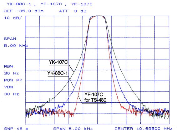
Three newly developed optional filters are available for the 2nd IF. Previously, there was only one
10.695MHz optional filter: the YK-107C (500Hz). This filter was developed at the same time as the
TS-790, and since the focus was on its use for V/UHF, there may have been times when users felt it was lacking when it came to HF operations. So when we were developing the TS-480, we redesigned the 500Hz filter, greatly improving its shape factor. We also used the opportunity to design new 270Hz and 1.8kHz (SSB narrow) filters.
Fig. 11 graphically illustrates the difference between these filters in the 500Hz band.
Fig. 11: Comparison of optional CW filters (500Hz)
18
Loading...