


DPSE-7

FM/AM RECEIVER
DIGITAL AUDIO
COMPACT
INSTRUCTION MANUAL
KENWOOD CORPORATION
B60-3330-00 JA (T)
AP
98/12 11 10 9 8 7 6 5 4 3 2 1 97/12 11 10 9 8 7 6 5
R-SE7
CD PLAYER
CASSETTE TAPE DECK
DP-SE7
X-SE7
WS
R-SE7/DP-SE7/X-SE7 (En)
2
Preparation sectionBasic sectionApplication sectionKnowledge sections
Before applying power
CAUTION: TO REDUCE THE RISK OF ELECTRIC SHOCK, DO NOT REMOVE
COVER (OR BACK). NO USER-SERVICEABLE P ARTS INSIDE, REFER SER VIC-
ING TO QUALIFIED SERVICE PERSONNEL.
RISK OF ELECTRIC SHOCK
DO NOT OPEN
THE LIGHTNING FLASH WITH ARROWHEAD SYMBOL, WITHIN AN EQUILATERAL TRIANGLE, IS
INTENDED TO ALERT THE USER TO THE PRESENCE OF UNINSULATED “DANGEROUS VOLTAGE”
WITHIN THE PRODUCT’S ENCLOSURE THAT MAY BE OF SUFFICIENT MAGNITUDE TO CONSTI-
TUTE A RISK OF ELECTRIC SHOCK TO PERSONS.
THE EXCLAMA TION POINT WITHIN AN EQUILA TERAL TRIANGLE IS INTENDED TO ALERT THE USER
TO THE PRESENCE OF IMPORT ANT OPERATING AND MAINTENANCE (SERVICING) INSTRUCTIONS
IN THE LITERATURE ACCOMPANYING THE APPLIANCE.
Units are designed for operation as follows.
Europe and U.K. .................................................AC 230 V only
U.S.A. and Canada ............................................ AC 120 V only
Factory fitted moulded mains plug
1.The mains plug contains a fuse. For replacement, use
only a 13-Amp ASTA-approved (BS1362) fuse.
2.The fuse cover must be refitted when replacing the
fuse in the moulded plug.
3.Do not cut off the mains plug from this equipment. If
the plug fitted is not suitable for the power points in
your home or the cable is too short to reach a power
point, then obtain an appropriate safety approved ex-
tension lead or adapter, or consult your dealer.
If nonetheless the mains plug is cut off, remove the
fuse and dispose of the plug immediately, to avoid a
possible shock hazard by inadvertent connection to
the mains supply.
IMPORTANT : The wires in the mains lead are coloured
in accordance with the following code:
Blue : Neutral
Brown : Live
Do not connect those leads to the earth terminal of a
three-pin plug.
For the United Kingdom
Safety precautions
WARNING : TO PREVENT FIRE OR ELECTRIC
SHOCK, DO NOT EXPOSE THIS AP-
PLIANCE TO RAIN OR MOISTURE.
CAUTION
Before applying power
The marking is located on the rear panel and says that
the component uses laser beams that have been clas-
sified as Class 1. It means that the unit is utilizing laser
beams that are of a weaker class. There is no danger of
hazardous radiation outside the unit.
CLASS 1
LASER PRODUCT
The marking of products using lasers
(Except for some areas)
Caution : Read this page carefully to ensure safe operation.

R-SE7/DP-SE7/X-SE7 (En)
3
Preparation section Basic section Application section Knowledge sections
Before applying power
Caution : Read the pages marked carefully to ensure safe operation.
Contents
Preparation section Application section
Basic section
Knowledge section
Before applying power ................................................. 2
Safety precautions .............................................................. 2
IMPORTANT SAFEGUARDS............................................... 4
The High grade Micro Component Series ...................... 6
About the Instruction Manual........................................... 6
Special features .................................................................. 7
System Composition and Installation......................... 8
System connection ........................................................ 9
Antenna connection............................................................ 9
Connection of audio cord ................................................ 10
Connection of speakers ................................................... 12
Connection of system control cord................................ 13
Power Cord Connection ................................................... 13
Controls and indicators............................................... 14
Main Unit ............................................................................ 14
Remote control Unit .......................................................... 16
Operation of remote control unit............................... 17
Hearing sound............................................................... 18
Basic use ............................................................................ 18
Playback of CD................................................................... 20
Playback of tape................................................................ 22
Receiving broadcast station ........................................... 26
Collective presetting of stations (auto preset)............ 27
One-by-one presetting (manual preset)........................ 27
Recording ...................................................................... 28
Recording............................................................................ 28
Playback of CD ............................................................. 31
Listening in the desired sequence
(program playback) ......................................................... 31
Repeated playback ........................................................... 33
Listening to an unexpected title sequence
(random playback)........................................................... 34
Convenient CD recording............................................ 35
Selecting the optimum recording method ........................... 35
Giving preference to the tape length
over the title sequence
(time edit recording) ....................................................... 36
Recording only desired titles
(ONE TOUCH EDIT ......single title recording) ....................... 37
One-touch recording of an entire CD
(ONE TOUCH EDIT ......recording of all titles) ....................... 38
R.D.S. (Radio Data System)......................................... 39
Searching for a desired program type
(PTY search) ..................................................................... 40
T o be able to listen to the desired information
at any time
(EON reservation) ............................................................ 42
Listening with high sound quality (Pure A)............. 43
Listening in Pure A mode................................................. 43
Clock adjustment ......................................................... 44
Timer operation ............................................................ 45
Operate easy To use Timer (O.T.T.)................................. 45
Sleep timer ......................................................................... 45
Timer programming........................................................... 46
Important items............................................................. 49
Handling of discs and tapes............................................ 49
Maintenance ...................................................................... 50
Reference............................................................................ 51
In case of difficulty ...................................................... 52
Specifications............................................................... 55

R-SE7/DP-SE7/X-SE7 (En)
4
Preparation sectionBasic sectionApplication sectionKnowledge sections
Before applying power
Please read all of the safety and operating instructions
before operating this appliance. Adhere to all warnings
on the appliance and in the instruction manual. Follow all the
safety and operating instructions. These safety and
operating instructions should be retained for future
reference.
1. Power sources – The appliance should be connected
to a power supply only of the type described in the
instruction manual or as marked on the appliance. If you
are not sure of the type of power supply to your home,
consult your appliance dealer or local power company.
For appliances intended to operate from battery power,
or other sources, refer to the instruction manual.
2. Power-cord protection – Power-supply cords
should be routed so that they are not likely to be
walked on or pinched by items placed upon or
against them, paying particular attention to cords
at plugs, convenience receptacles, and the point
where they exit from the appliance.
3. CAUTION – Polarization – This appliance may be
equipped with a polarized alternating-current line plug (a
plug having one blade wider than the other). This plug
will fit into the power outlet only one way. This is a
safety feature. If you are unable to insert the plug fully
into the outlet, try reversing the plug. If the plug should
still fail to fit, contact your electrician to replace your
obsolete outlet. Do not defeat the safety purpose of the
polarized plug.
4. Ventilation – Slots and openings in the cabinet are
provided for ventilation and to ensure reliable operation
of the appliance and to protect it from overheating, and
these openings must not be blocked or covered. The
appliance should be situated so that its location or
position does not interfere with its proper ventilation.
To maintain good ventilation, do not put records or a
table-cloth on the appliance. Place the appliance at least
10 cm away from the walls.
Do not use the appliance on a bed, sofa, rug or similar
surface that may block the ventilation openings. This
appliance should not be placed in a built-in installation
such as a bookcase or rack unless proper ventilation is
provided or the manufacturer’s instructions have been
adhered to.
5. Water and moisture – The appliance should not
be used near water - for example, near a bathtub,
washbowl, kitchen sink, laundry tub, in a wet
basement, or near a swimming pool, etc.
6. Temperature – The appliance may not function
properly if used at extremely low, or freezing
temperatures. The ideal ambient temperature is
above +5°C (41°F).
IMPORTANT SAFEGUARDS
Caution : Read this page carefully to ensure safe
operation.
7. Heat – The appliance should be situated away
from heat sources such as radiators, heat registers,
stoves, or other appliances (including amplifiers)
that produce heat.
8. Electric shock – Care should be taken so that
objects do not fall and liquid is not spilled into the
enclosure through openings. If a metal objects,
such as a hair pin or a needle, comes into contact
with the inside of this appliance, a dangerous
electric shock may result. For families with
children, never permit children to put anything,
especially metal, inside this appliance.
9. Enclosure removal – Never remove the enclosure.
If the internal parts are touched accidentally, a
serious electric shock might occur.
10.Magnetic fields – Keep the appliance away from
sources of magnetic fields such as TV sets, speaker
systems, radios, motorized toys or magnetized
objects.
11.Cleaning – Unplug this appliance from the wall
outlet before cleaning. Do not use volatile solvents
such as alcohol, paint thinner, gasoline, or benzine,
etc. to clean the cabinet. Use a clean dry cloth.
12.Accessories – Do not place this appliance on an unstable
cart, stand, tripod, bracket, or table. The appliance may
fall, causing serious injury to a child or adult, and serious
damage to the appliance. Use only with a cart, stand,
tripod, bracket, or table recommended by the
manufacturer, or sold with the appliance. Any mounting
of the appliance should follow the manufacturer’s
instructions, and should use a mounting accessory
recommended by the manufacturer. An appliance and
cart combination should be moved with care. Quick
stops, excessive force, and uneven surfaces may cause
the appliance and cart combination to overturn.
13.Lightning – For added protection for this appliance
during a lightning storm, or when it is left unattended
and unused for long periods of time, unplug it from the
wall outlet and disconnect the antenna or cable system.
This will prevent damage to the appliance due to lightning
and power-line surges.
14.Abnormal smell – If an abnormal smell or smoke
is detected, immediately turn the power OFF and
unplug the appliance from the wall outlet. Contact
your dealer or nearest service center.

R-SE7/DP-SE7/X-SE7 (En)
5
Preparation section Basic section Application section Knowledge sections
Before applying power
18.Power lines – An outside antenna system should not
be located in the vicinity of overhead power lines or
other electric light or power circuits, or where it can fall
into such power lines or circuits. When installing an
outside antenna system, extreme care should be taken
to keep from touching such power lines or circuits as
contact with them might be fatal.
19.AC outlets – Do not connect other audio
equipment with a power consumption larger than
that specified to the AC outlet on the rear panel.
Never connect other electrical appliances, such
as an iron or toaster, to it to prevent fire or electric
shock.
20. Overloading – Do not overload wall outlets, extension
cords, or integral convenience receptacles as this can
result in a risk of fire or electric shock.
21. Attachment – Do not use attachments not
recommended by the appliance manufacturer as they
may cause hazards.
22. Replacement parts – When replacement parts are
required, be sure the service technician has used
replacement parts specified by the manufacturer or
have the same characteristics as the original parts.
Unauthorized substitutions may result in fire, electric
shock, or other hazards.
23. Safety check – Upon completion of any service or
repairs to this appliance, ask the service technician to
perform safety checks to determine that the appliance
is in proper operating condition.
15.Damage requiring service – The appliance should
be serviced by qualified service personnel when:
A. The power-supply cord or the plug has been
damaged.
B. Objects have fallen, or liquid has been spilled into
the appliance.
C. The appliance has been exposed to rain or water.
D. The appliance does not appear to operate normally
by following the instruction manual. Adjust only those
controls that are covered by the instruction manual as
an improper adjustment of other controls may result in
damage and will often require extensive work by a
qualified technician to restore the appliance to its normal
operation.
E. The appliance has been dropped, or the enclosure
damaged.
F. The appliance exhibits a marked change in performance.
16.Servicing – The user should not attempt to
service the appliance beyond that described in the
instruction manual. All other servicing should be
referred to qualified service personnel.
17.Outdoor antenna grounding – If an outside
antenna is connected to the appliance, be sure the
antenna system is grounded so as to provide
some protection against voltage surges and built
up static charges. Article 810 of the National
Electrical Code ANSI/NFPA 70, provides
information with respect to proper grounding of
the mast and supporting structure, grounding of
the lead-in wire to an antenna discharge unit, size
of grounding conductors, location of antenna
discharge unit, connection to grounding
electrodes, and requirements for the grounding
electrode. See Figure.
Caution : Read this page carefully to ensure safe
operation.
Notes:
1. Item 3 is not required except for grounded or polarized
equipment.
2. Item 17 and 18 are not required except for units provided with
antenna terminals.
3. Item 17 complies with UL in the U.S.A.
EXAMPLE OF ANTENNA GROUNDING AS PER
NATIONAL ELECTRICAL CODE
ANTENNA
DISCHARGE UNIT
(NEC SECTION 810-20)
POWER SERVICE GROUNDING
ELECTRODE SYSTEM
(NEC ART 250, PART H)
GROUND CLAMP
ANTENNA
LEAD IN WIRE
GROUND
CLAMPS
ELECTRIC
SERVICE
EQUIPMENT
NEC – NATIONAL ELECTRICAL CODE
GROUNDING CONDUCTORS
(NEC SECTION 810-21)

R-SE7/DP-SE7/X-SE7 (En)
6
Preparation sectionBasic sectionApplication sectionKnowledge sections
Before applying power
The High grade Micro Component Series
Thank you for purchasing the High grade Micro component series.
This system is available in various configuration according to your preferences.
The system configuration is up to you, but as the following convenient system operations can be
executed by connecting the various units to the system control, the respective units should be pur-
chased as required.
Remote Control
The remote control supplied with the receiver can be used for basic operation of the source units (CD
player, cassette deck, MD recorder).
Automatic Operation
When playback is started on the playback source unit, the input selector on the amp tuner will
automatically be set to input for that source unit. Also, when source input is selected on the amp tuner,
playback of the input source unit will be started automatically.
Synchronized Recording
With recording from CD or MD, it is possible to start synchronized recording by the recording unit (MD
recorder or cassette deck). (Recording from one MD recorder onto another one is not possible.)
There are also other convenient functions like one-touch edit recording for CD and MD etc.
T imer Operation
The clock function of the receiver can be used for timer playback and timer recording of source equipment
(CD player, cassette deck, MD recorder).
High grade Micro Component Series components
R-SE7 (receiver) X-SE7 (cassette deck)
DP-SE7 (CD player) DM-SE7 (MD recorder)
About the Instruction Manual
While some models of the High grade Micro component series have an instruction manual explaining
the system operation for R-SE7 (receiver), DP-SE7 (CD player), and X-SE7 (cassette deck), other models
have only an operation manual for that model itself. This is done so that the system operation can be
done easily even when optional equipment is purchased at a later date. Please read the required sections
according to the components you purchased.
With the High grade Micro component series, the system explanations show only the connection method
for the DM-SE7 (MD recorder). Please refer to the instruction manual enclosed with the DM-SE7 for the
detailed operation.
Model name Enclosed instruction manual
(name of the purchased component) (explained models)
Basic system (R-SE7, DP-SE7) System instruction manual (R-SE7, DP-SE7, X-SE7)
Cassette deck (X-SE7) Individual instruction manual (X-SE7)
MD recorder (DM-SE7) Individual instruction manual (DM-SE7)
7 There are 2 lines in the High grade Micro Component Series, SE7 and SE9, you can use optional
components from either series.

R-SE7/DP-SE7/X-SE7 (En)
7
Preparation section Basic section Application section Knowledge sections
Before applying power
¶ Easy Operation
When the High grade Micro component series is connected to the system control, input switching with the
input selector (TAPE, TUNER, CD, MD) of the R-SE7 will start playback by the selected unit. Reversely, when
playback is started from a unit, the input will be switched automatically to this unit.
Accessories
When listening with low volume close to the set or late at night, we recommend the “Pure A” operation mode. Then you
can enjoy smooth high-quality sound with little distortion. Please use the normal mode to listen at higher volumes.
¶
“Pure A” High Quality Mode at Low Volume e
Time edit recording: Recording so that no track is interrupted within the specified time.
One-touch edit recording: When listening to a CD, either a single track or the entire CD can be recorded on tape
by one-touch operation.
¶
Convenient Edit Recording fl
Unpacking
Unpack the unit carefully and make sure that all accessories are put aside so they will not be lost.
Examine the unit for any possibility of shipping damage. If your unit is damaged or fails to operate, notify your dealer immedi-
ately. If your unit was shipped to you directly, notify the shipping company without delay. Only the consignee (the person or
company receiving the unit) can file a claim against the carrier for shipping damage.
We recommend that you retain the original carton and packing materials for use should you transport or ship the unit in the future.
The wake-up timer and the sleep timer can be set easily.
A daily program timer also can be reserved.
¶
Simple Timer Operation t
Accessories using with R-SE7
AM loop antenna (1)
Loop antenna stand (1)
FM indoor antenna (1)
Remote control unit (1)
Batteries (R6/AA) (2)
Accessories using with DP-SE7
Audio cord (1)
System control cord (1)
Accessories supplied with X-SE7
Audio cord (2)
System control cord (1)
Special features
The RDS data included in FM broadcasts can be used to search for the intended broadcasting contents and for
automatic reception from standby.
¶
R.D.S. (Radio Data System) ·
7 Amplifier unit that accomplishes high grade sound quality and low distortion
¶ CD TEXT compatibility
Disc title and track names recorded on the CD appear in the display of the MD player (DM-SE7: sold separately).
7 CD player unit that accomplishes improved sound quality and stability
¶ Newly developed D.R.I.V.E. IC installed
A D.R.I.V.E. (Dynamic Resolution Incentive Vector Enhancement) IC that rapidly improves distortion at minute
levels is installed in the CD player in order to extract the maximum performance possible from the CD.
7 Convenient easy to use operation
R-SE7/DP-SE7/X-SE7 (En)
8
Preparation sectionBasic sectionApplication sectionKnowledge sections
System connection
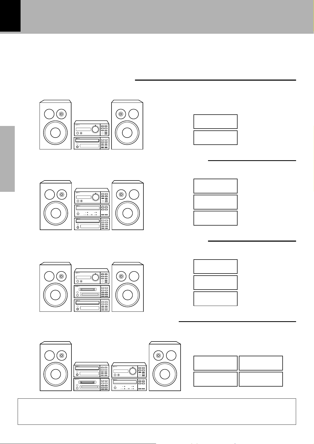
System Composition and Installation
The High grade Micro component series permits various combinations according to the purchased
components. As the installation differs according to the components you purchase, please install cor-
rectly under reference to the illustrations.
Basic System (R-SE7, DP-SE7)
Seen from the front Installation method
R-SE7
DP-SE7
Basic System + MD recorder (R-SE7, DP-SE7, DM-SE7)
Seen from the front Installation method
DP-SE7
R-SE7
Basic System + Cassette Deck (R-SE7, DP-SE7, X-SE7)
Seen from the front Installation method
X-SE7
(optional)
DP-SE7
R-SE7
Full System (R-SE7, DP-SE7, DM-SE7 X-SE7)
Seen from the front Installation method
R-SE7DP-SE7
DM-SE7
(optional)
DM-SE7
(optional)
X-SE7
(optional)
When the power of the R-SE7 (receiver) is switched on, the heat generated on the inside is
radiated to the outside. Always install the R-SE7 on top, and don't place any objects impairing
heat radiation onto the top of the unit.
CAUTION
disc loading mechanism
disc loading mechanism
R-SE7/DP-SE7/X-SE7 (En)
9
Preparation section Basic section Application section Knowledge sections
System connection
SYSTEM
CONTROL
ANTENNA
AM
GND
FM75
CD
IN IN REC PLAY
SUPER
WOOFER
PRE OUT
SPEAKERS
( 6 - 16 )
L
R
TAPE
REC PLAY
MDAUX
R
L
ANTENNA
AM
GND
FM75
ANTENNA
AM
GND
FM75
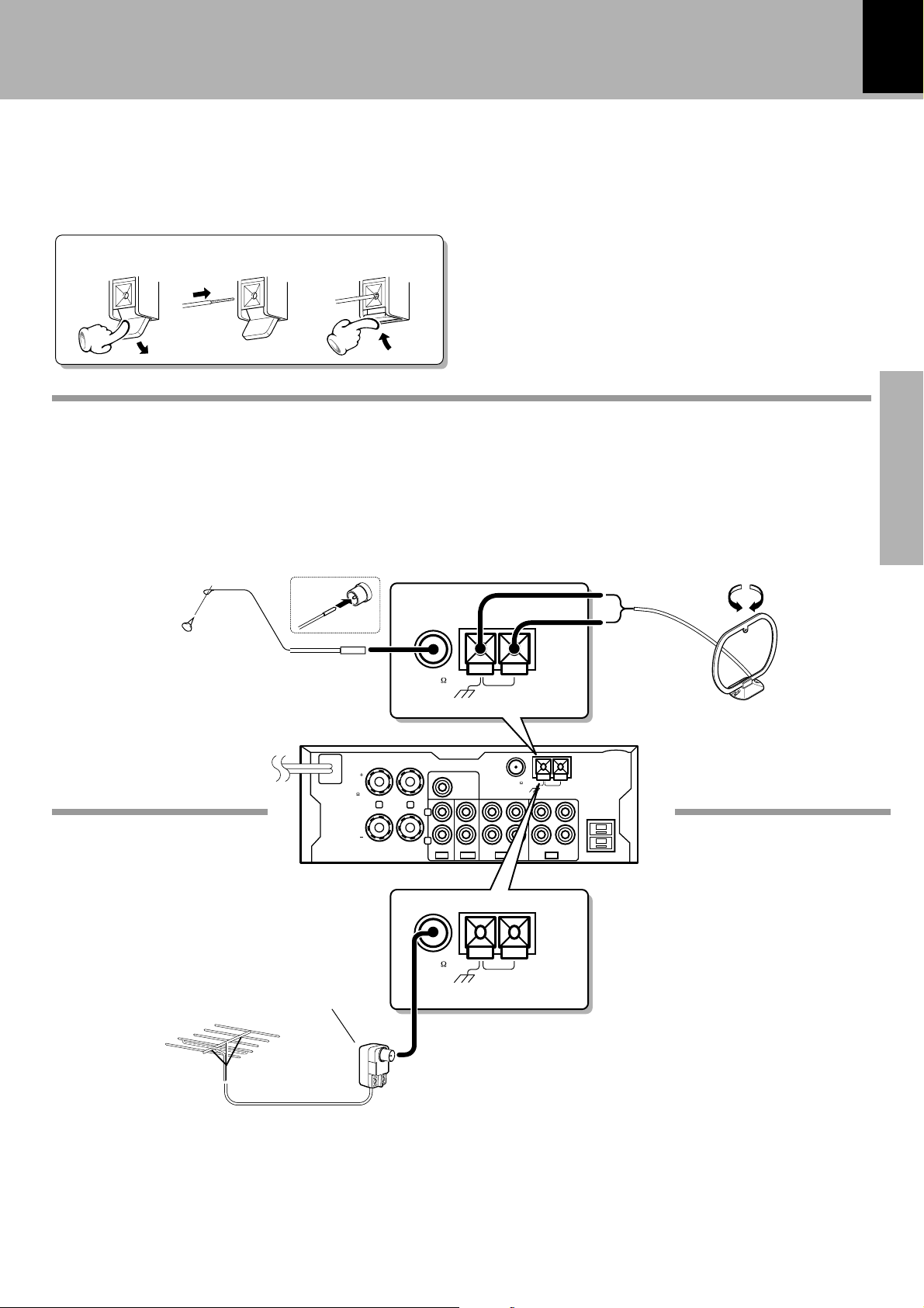
System connection
Connect the antenna as shown in the figure.
Do not plug the power cord into a wall AC outlet until the connection has been completed.
1. Antenna connection
123
Connection of the Accessory Antenna
FM indoor antenna
The accessory antenna is for temporary indoor use only.
For stable signal reception we recommend using an out-
door antenna. Remove the indoor antenna if you connect
one outdoors.
1 Strip the coating from the tip of
cord and twist the conductor.
2 Locate the position providing good
reception condition.
3 Fix the antenna.
AM loop antenna
The supplied antenna is for indoor use. Place it as far as
possible from the main system, TV set, speaker cords and
power cord, and set it to a direction which provides the
best reception.
FM outdoor antenna
Lead the 75Ω coaxial cable connected to the FM outdoor
antenna into the room and connect it to the FM 75Ω
termimal.
Antenna adapter
(commercially
available)
FM outdoor
antenna
(commercially
available)
AM loop
antenna
FM indoor
antenna
In case of bad reception
R-SE7
R-SE7/DP-SE7/X-SE7 (En)
10
Preparation sectionBasic sectionApplication sectionKnowledge sections
System connection
SYSTEM
CONTROL
ANTENNA
AM
GND
FM75
CD
IN IN REC PLAY
SUPER
WOOFER
PRE OUT
SPEAKERS
( 6 - 16 )
L
R
TAPE
REC PLAY
MDAUX
R
L
SYSTEM
CONTROL
REC
IN
PLAY
OUT
L
R
[ ]
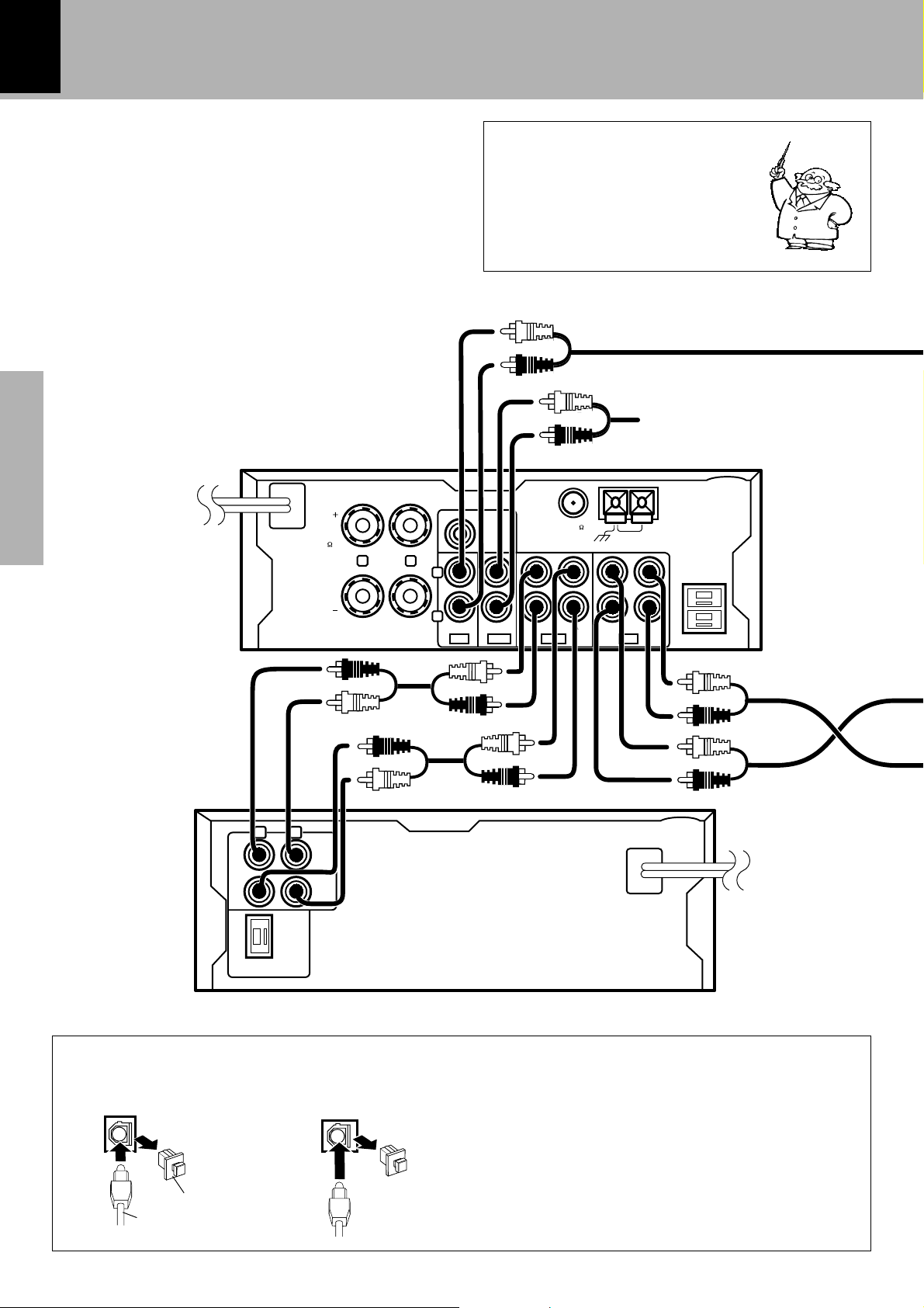
Here, connection of separately sold components
also will be explained under consideration of
system connection. Please install correctly
according to the purchased components and
connect the required cords.
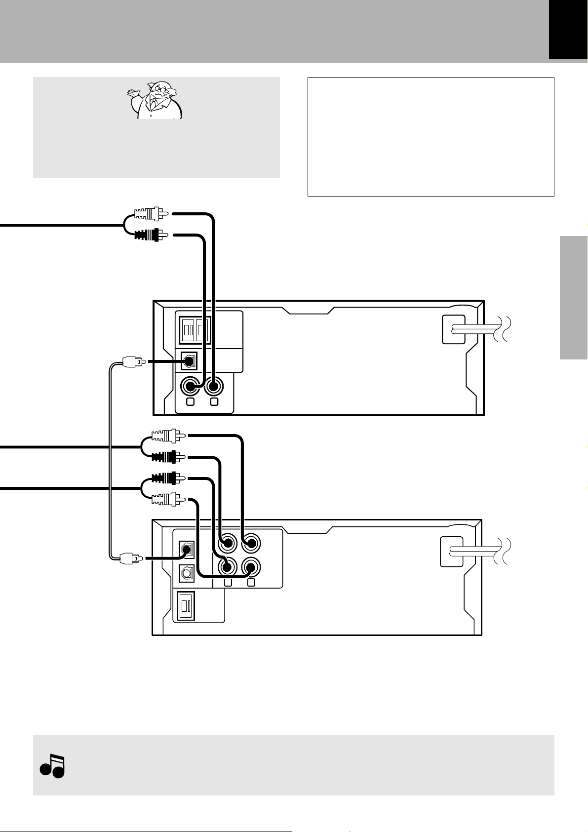
2. Connection of audio cord
Malfunction of microcomputer
If operation is not possible or erro-
neous display appears even though
all connections have been made
properly, reset the microcomputer re-
ferring to “In case of difficulty”.
W
DIGITAL
OUTPUT
OPTICAL
DIGITAL IN
OPTICAL
Connection with Optical Fiber Cable
This is used for digital connections. Digital trans-
mission permits recording without loss of the
high CD sound quality.
Remove the cap and connect an optical fiber
cable.
Remove cap
Optical fiber cable
DP-SE7
DM-SE7
Audio cord (Supplied with R-SE7)
Audio cord (x2)
(Supplied with
X-SE7)
R-SE7
X-SE7 (optional)
Optional record player with internal
RIAA equalizer/amp (P-100)
or videodeck (etc.).
R-SE7/DP-SE7/X-SE7 (En)
11
Preparation section Basic section Application section Knowledge sections
System connection
Caution regarding placement
To maintain proper ventilation, be sure to leave a
space around the unit (from the largest outer dimen-
sions including projections) equal to, or greater than,
shown below.
top panel : 50cm
side panel : 10cm
rear panel : 10cm
DIGITAL
OUTPUT
OPTICAL
SYSTEM
CONTROL
LINE OUTPUT
LR
LR
DIGITAL IN
OPTICAL
SYSTEM
CONTROL
REC
IN
PLAY
OUT
1
2
1.In case an associated system component is connected, also read the instruction manual of the component.
2.Insert the optical-fiber cable straight into the connector until it clicks.
3.Be sure to attach the protection cap when the connector is not used.
4.Be careful not to bend, coil or bundle the optical fiber cable.
Notes
Notes
Caution for Connection
When connections are to be made, make sure that
the power plug is not plugged into a wall AC outlet.
Connect the equipment as shown in the figures.
DP-SE7
DM-SE7 (optional)
Optical
fiber cable
(Supplied
with DM-SE7)
Audio cord (x2)
(Supplied with DM-SE7)
R-SE7/DP-SE7/X-SE7 (En)
12
Preparation sectionBasic sectionApplication sectionKnowledge sections
System connection
SYSTEM
CONTROL
ANTENNA
AM
GND
FM75
CD
IN IN REC PLAY
SUPER
WOOFER
PRE OUT
SPEAKERS
( 6 - 16 )
L
R
TAPE
REC PLAY
MDAUX
R
L
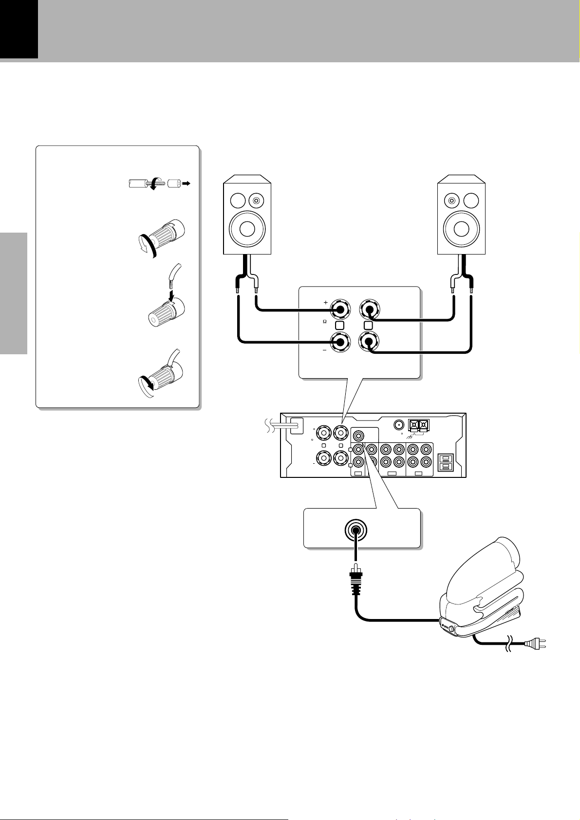
SPEAKERS
( 6 - 16 )
L
R
SUPER
WOOFER
PRE OUT
Speaker (right)
(6-16Ω)
Connect the speakers as shown in the figure.
Do not plug the power cord into a wall AC outlet until the connection has been completed.
3. Connection of speakers
1 Cord preparation.
2 Loosen.
3 Insert.
4 Secure.
R-SE7
¶ Never short-circuit the + and – speaker cords.
The protection circuit will operate and no sound will
be put out.
¶ If the left and right speaker connections or the + and
– polarity are inverted, the sound will be unnatural
with unclear localization of musical instruments, etc.
Be sure to connect them without mistake.
Speaker (left)
(6-16Ω)
·ª ª·
Super woofer (SW-500) (optional)
Extremely low frequency sound is played back powerfully.
This can be used with any type of playback.
R-SE7/DP-SE7/X-SE7 (En)
13
Preparation section Basic section Application section Knowledge sections
System connection
SYSTEM
CONTROL
ANTENNA
AM
GND
FM75
CD
IN IN REC PLAY
SUPER
WOOFER
PRE OUT
SPEAKERS
( 6 - 16 )
L
R
TAPE
REC PLAY
MDAUX
R
L
DIGITAL
OUTPUT
OPTICAL
SYSTEM
CONTROL
LINE OUTPUT
LR
SYSTEM
CONTROL
REC
IN
PLAY
OUT
L
R
LR
DIGITAL IN
OPTICAL
SYSTEM
CONTROL
REC
IN
PLAY
OUT
1
2
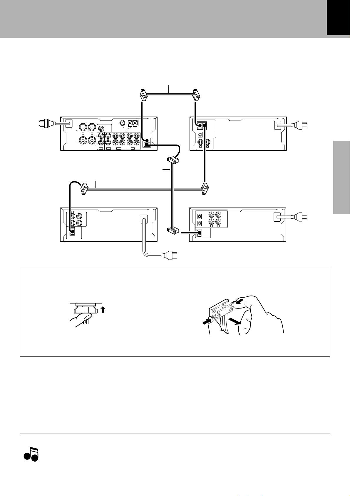
Connect the system control cords and the power cords as shown in the figure.
4. Connection of system control cord
Connection of system control cord
Insert the plug straight into the connector until it locks.
Plugging the connector
While pushing the two sides of connector in, pull it
straight out.
Unplugging the connector
To wall
AC outlet
To wall
AC outlet
To wall
AC outlet
To wall
AC outlet
System control cord
(Supplied with R-SE7)
System control cord
(Supplied with X-SE7)
R-SE7
DM-SE7 (optional)
DP-SE7
X-SE7 (optional)
Insert the power cord plug into a wall AC outlet after all other connections have been completed.
5. Power Cord Connection
1.Be sure to insert all connection cords securely. If their connections are imperfect, the sound may not be produced
or noise may interfere.
2.Before plugging or unplugging a connection cord, be sure to unplug the power cord from the wall AC outlet.
If connection cords are plugged or unplugged with the power cord left plugged in, malfunction or damage may
result.
Notes
Notes
System control
cord (Supplied
with DM-SE7)
R-SE7/DP-SE7/X-SE7 (En)
14
Preparation sectionBasic sectionApplication sectionKnowledge sections
Controls and indicators
STANDBY
PGM
12345
678910
11 12 13 14 15
88
-8 8
:
88
TRACK NO. REPEAT EDIT
RANDOM
TOTAL SPACEA B
60
repeat 7
¢4
1 ¡
timespace
compact disc player
DP-SE7
on/standby
D.R.I.V.E.
'
****** **;
TUNED RDS EON PTY TPST.AUTOMUTE
N.B. SLEEP
TA NEWS INFO
A.P.S. O.T.T.
kHz MEMO.
MHz PROG.
∞∞
stereo integrated amplifier/tuner
on/standby
phones
down up
volume
control
pure
input selector
N.B.
pure
enter
%
band
auto/mono
fi
turning
R-SE7
A
A
on/standby
rev. mode
Dolby NR CRLSBC
¶
1
0
2
7
3
¡
8
”
stereo auto reverse cassette deck
X-SE7
2
1
1
2
1
2
3
3
4
7
8
9
0
!
@
4
5
6
7
8
9
4
5
7
8
9
0
!
6
5
3
!
6
0
- front loading mechanism -
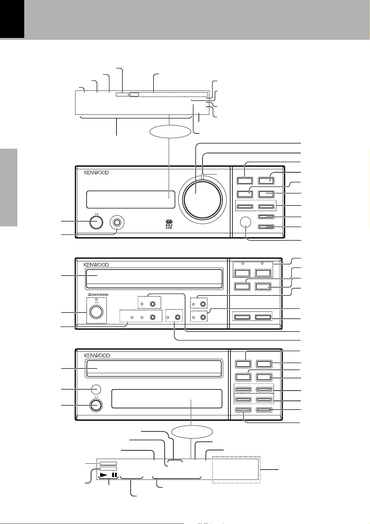
Controls and indicators
Main Unit
Memory indicator
Display
REPEAT indicator
Playback/Pause indicator
RANDOM indicator
Display
Frequency level display and
Character information display
Program mode
indicator
Track number display
STANDBY indicator
Track number display
Time display
Indicator of A and B (EDIT mode)
TUNED indicator
TOTAL indicator
SPACE indicator
Stereo reception indicator
AUTO indicator
O.T.T. indicator
N.B. indicator
Timer Program indicator
Sleep timer indicator
A.P.S. indicator
Receiver R-SE7
Cassete deck X-SE7 (optional)
CD player DP-SE7
MUTE indicator
RDS display

R-SE7/DP-SE7/X-SE7 (En)
15
Preparation section Basic section Application section Knowledge sections
Controls and indicators
Receiver R-SE7
1 “on/standby” key *
The power is switched ON and OFF (standby). At the
time of system connection, the power is switched ON
and OFF for the entire system.
2 “phones” jack (
Headphones with a stereo mini plug (optional) can be
connected.
3 “volume control” knob *
Normally, this is used to adjust the volume. It is also
used for timer reservation and clock setting.
4 Pure A indicator e
This lights at the time of pure A mode.
5 “pure A” key (e
When the power is ON : Switches Pure A mode ON/
OFF.
When the power is OFF: Switches A.P.S. (auto power
save) ON/OFF.
6 N.B. key (
This is used for bass and treble compensation.
CD player DP-SE7
1 Disc tray )
One disc can be stored.
2 Remote control sensor
This is not used with system connection.
3 “on/standby” key
The power is switched ON and OFF (standby). This is
not used with system connection.
4 Open/Close key (0) )
The disc tray is opened and closed.
Cassete deck X-SE7
1 Tape tray ™
This houses the cassette tape.
2 “on/standby” key/Standby indicator
The power is switched ON and OFF (standby). This is
not used in case of system connection.
3 Dolby NR key/indicators £
Dolby noise reduction ON/OFF switching is executed.
4 Playback keys (2 3)/Operation indicator ™
During stop and pause: the tape direction lights red.
During playback and recording: the tape direction lights
green.
During fast forward and rewind: the tape direction
flashes green.
5 Open/Close key (0) ™
This opens the tape tray for tape insertion and removal.
6 Stop (7) key £
7 “enter” key ¶r
Used for time setting, timer setting, presetting RDS
stations, storing radio stations etc.
8 “input selector" key *
This selects the input source. When TAPE, CD, or MD
is selected and a tape or disc already has been set,
playback starts automatically.
9 “tuning” (% fi) key §ti
When the power is ON : Used for station tuning.
When the power is OFF: Used for timer reservation.
%key: Program ON/OFF
fikey: O.T.T. reservation
0 “band” key §i
When the power is ON : Reception band switching.
When the power is OFF: Used for timer reservation.
! “auto/mono” key ¶r
When the power is ON : The tuning mode is switched.
When the power is OFF: Used for clock setting.
@ Remote control sensor &
This is used with the R-SE7 system remote control
(RC-SE9).
7 Pause (8) key/indicator £
8 Record (¶) key/indicator •
Recording is started. When this switch is pressed
during recording, an unrecorded (blank) portion of about
4 sec is produced and then the tape stops.
9 Fast forward and rewind (1 ¡) keys £
0
“rev. mode” key/indicator £
The reverse mode of the deck (both sides, one side) is
switched.
! CRLS key/indicator º
The recording level is set automatically according to the
sound source being recorded.
5 Playback/Pause key (6) )
6 “repeat” key ‹
This is used for repeated playback of a CD.
7 Stop (7) key ¡
8 Skip (4 ¢) key ¡
9 Fast forward, rewind (1 ¡) key ¡
0 “time” key ¡
The CD time display is switched.
! “space” key ¤
During program playback, a silent part of several sec-
onds is produced between tracks.
R-SE7/DP-SE7/X-SE7 (En)
16
Preparation sectionBasic sectionApplication sectionKnowledge sections
Controls and indicators
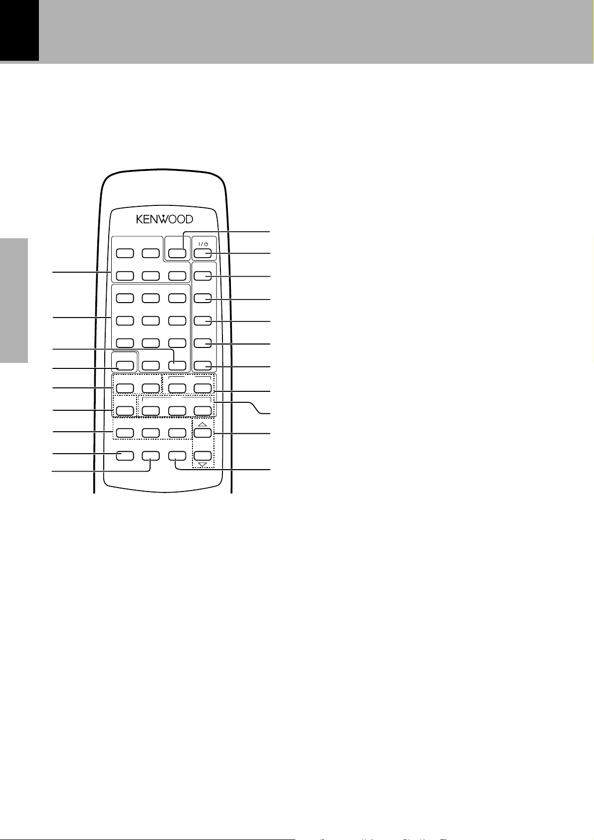
1 Cassette deck operation keys ™
These keys are used to operate the cassette deck
(X-SE7).
2 Numeric keys ¡¶
These keys can be used as numeric keys when CD
or MD is selected as input. When TUNER is se-
lected as input, preset stations can be called.
3 PTY SEARCH/+10 key ‚
This is used to specify the program type and to search
for a station.
4 O.T.E. key fi
When this key is pressed during CD or MD playback,
only the track being played at that time will be recorded
on tape. When this key is pressed during stop, the CD
or MD selected at that time will be recorded on tape
from the first track onward.
5 4 ¢ key ¡§
(Skip/Preset call)
When TUNER is selected:
This is used as preset call key.
When CD or MD is selected:
This is used as skip key.
6 BAND key §
This is used to switch the tuner reception bands.
7 Keys related to RDS ·
RDS DISPLAY key
The display contents are switched during reception
of RDS broadcasts.
PTY (Program Type) key
This is used to specify the program type when
searching for a station.
TA/NEWS/INFO key
Used for automatic reception of transmissions of a
certain content.
8 INPUT key *
This key selects the input source. When TAPE, CD, or
MD is selected and a tape or disc already has been set,
playback starts automatically.
9 N.B. key (
This is used for bass and treble compensation.
0 SLEEP key t
Use to set the sleep timer.
! on/standby key *
The power for the receiver is switched ON and OFF
(standby). At the time of system connection, the power
is switched ON and OFF for the entire system.
@ DISPLAY key ¶
Switches the display on the AMP/TUNER (R-SE7)
(between the clock display and the input display).
# RANDOM key ›
Selects CD or MD tracks randomly for playback.
$ CLEAR key ¤
The contents of the CD program playback are cleared
title by title from the end.
% P.MODE keys ⁄
Used to program the CD playback sequence.
^ EDIT key fl
Used for CD edit recording (time edit recording).
& CD operation keys ¡
These keys are used to operate the CD player.
* MD operation keys
These keys are used to operate the MD recorder
(DM-SE7).
( VOLUME CONTROL keys *
This has the same function as the volume control knob
on the main unit. However, the AI VOLUME function
does not operate.
) MUTE key (
This is used to mute the sound temporarily.
When the system control cord is connected, this remote control can be used to operate the entire
system.
The keys on the remote control unit with the same names as on the main unit have the same function
as the keys on the main unit.
Remote control Unit [RC-SE9(E)]
7 DISPLAY
SLEEPTAPE
1¡
23
REMOTE CONTROL UNIT
RC-SE9 (E)
1 2 3 RANDOM
4 5 6 CLEAR
7 8 9 P.MODE
O.T.E. 0 EDIT
4¢ 7 6
TUNER
BAND
783
INPUT N.B. MUTE
VOLUME
CONTROL
MD
CDP.CALL
PTY
RDS
DISPLAY
PTY SEARCH
+10
TA/
NEWS/INFO.
!
@
0
#
&
*
1
2
4
5
6
7
$
%
^
(
3
)
8
9
R-SE7/DP-SE7/X-SE7 (En)
17
Preparation section Basic section Application section Knowledge sections
Operation of remote control unit
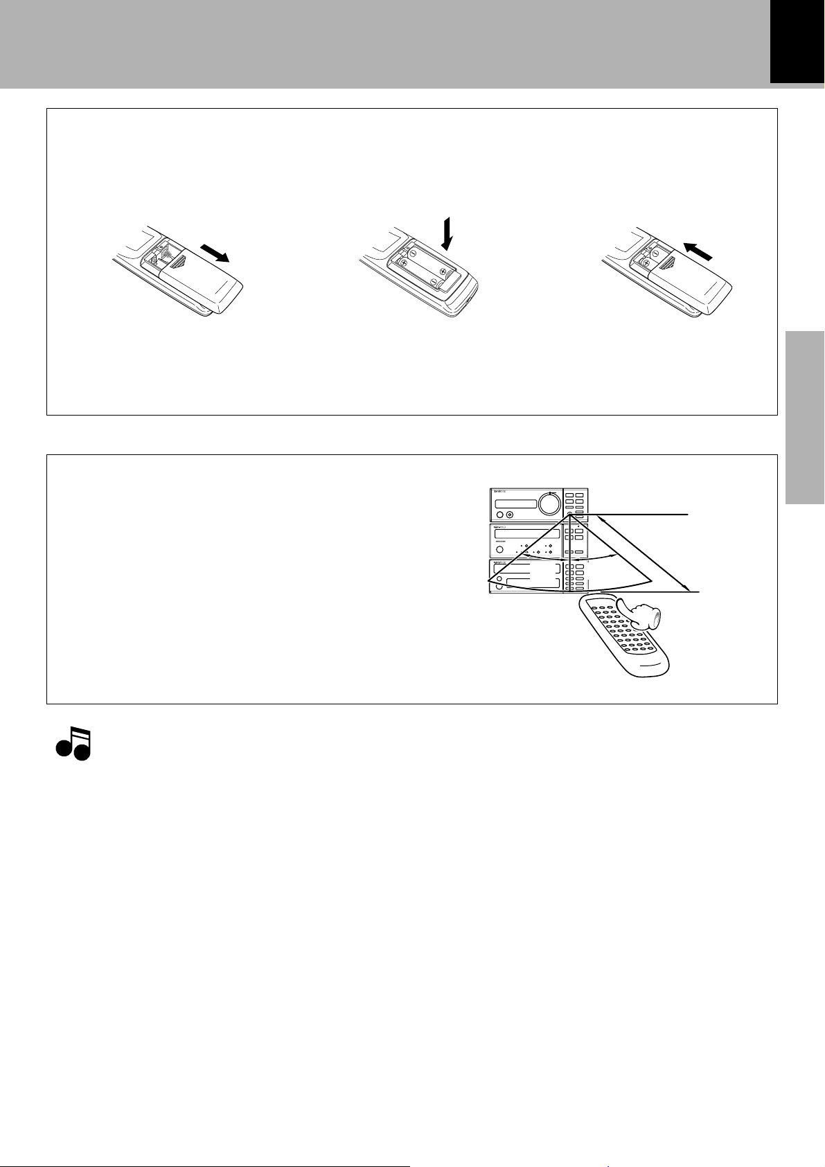
Operation
Loading batteries
2 Insert batteries. 3 Close the cover.
÷ When pressing more than one remote control keys
successively, press the keys securely by leaving an
interval of 1 second or more between keys.
After plugging the power cord of this unit, press
the on/standby key of the remote control unit to
turn the power of the system ON. When the
power is turned ON, press the key of the function
to be operated.
1.The provided batteries are intended for use in operation checking, and their service life may be short.
2.When the remote controllable distance becomes short, replace both of the batteries with new ones.
3.If direct sunlight or the light of a high- frequency fluorescent lamp (inverter type, etc.) is incident to the remote
sensor, malfunction may occur. In such a case, change the installation position to avoid malfunction.
1 Remove the cover.
÷ Insert two R6 (“AA”-size) batteries following the polarity indications.
Operation of remote control unit
Notes
Notes
Operating range (approx.)
Remote
sensor
Model: RC-SE9(E)
Infrared ray system
30° 30°
6 m
 Loading...