


 Loading...
STX-15F
JET SKI® Watercraft
Service Manual
 is a trademark of Kawasaki Heavy Industries, Ltd. registered in U.S.A., Japan, Austria, Benelux, Sweden, Denmark, Switzerland, France, Canada, Finland, Norway, Greece, Italy, U.K., Portugal, Thailand, and Taiwan.
KAWASAKI JET SKI® is a trademark of Kawasaki Heavy Industries, Ltd. registered in Australia.

Quick Reference Guide
This quick reference guide will assist you in locating a desired topic or procedure.
•Bend the pages back to match the black tab of the desired chapter number with the black tab on the edge at each table of contents page.
•Refer to the sectional table of contents for the exact pages to locate the specific topic required.
General Information |
1 |
j |
|
|
|
Periodic Maintenance |
2 |
j |
|
|
|
Fuel System (DFI) |
3 |
j |
|
|
|
Engine Lubrication System |
4 |
j |
|
|
|
Exhaust System |
5 |
j |
|
|
|
Engine Top End |
6 |
j |
|
|
|
Engine Removal/Installation |
7 |
j |
|
|
|
Engine Bottom End |
8 |
j |
|
|
|
Cooling and Bilge Systems |
9 |
j |
|
|
|
Drive System |
10 |
j |
|
|
|
Pump and Impeller |
11 |
j |
|
|
|
Steering |
12 |
j |
|
|
|
Hull/Engine Hood |
13 |
j |
|
|
|
Electrical System |
14 |
j |
|
|
|
Storage |
15 |
j |
|
|
|
Appendix |
16 |
j |

STX-15F
JET SKI® Watercraft
Service Manual
All rights reserved. No parts of this publication may be reproduced, stored in a retrieval system, or transmitted in any form or by any means, electronic mechanical photocopying, recording or otherwise, without the prior written permission of Quality Assurance Department/Consumer Products and Machinery Company/Kawasaki Heavy Industries, Ltd., Japan.
No liability can be accepted for any inaccuracies or omissions in this publication, although every possible care has been taken to make it as complete and accurate as possible.
The right is reserved to make changes at any time without prior notice and without incurring an obligation to make such changes to products manufactured previously. See your JET SKI® watercraft dealer for the latest information on product improvements incorporated after this publication.
All information contained in this publication is based on the latest product information available at the time of publication. Illustrations and photographs in this publication are intended for reference use only and may not depict actual model component parts.
© 2003 Kawasaki Heavy Industries, Ltd. |
Second Edition (1):Oct. 15, 2004 (K) |
LIST OF ABBREVIATIONS
A |
ampere(s) |
lb |
pound(s) |
ABDC |
after bottom dead center |
m |
meter(s) |
AC |
alternating current |
min |
minute(s) |
ATDC |
after top dead center |
N |
newton(s) |
BBDC |
before bottom dead center |
Pa |
pascal(s) |
BDC |
bottom dead center |
PS |
horsepower |
BTDC |
before top dead center |
psi |
pound(s) per square inch |
°C |
degree(s) Celsius |
r |
revolution |
DC |
direct current |
rpm |
revolution(s) perminute |
F |
farad(s) |
TDC |
top dead center |
°F |
degree(s) Fahrenheit |
TIR |
total indicator reading |
ft |
foot, feet |
V |
volt(s) |
g |
gram(s) |
W |
watt(s) |
h |
hour(s) |
Ω |
ohm(s) |
L |
liter(s) |
|
|
Read OWNER’S MANUAL before operating.
MAINTENANCE AND ADJUSTMENTS
Maintenance, replacement, or repair of the emission control devices and systems may be performed by any marine Sl engine repair establishment or individual.
EMISSION CONTROL INFORMATION
Fuel Information
THIS ENGINE IS CERTIFIED TO OPERATE ON UNLEADED REGULAR GRADE GASOLINE ONLY.
A minimum of 87 octane of the antiknock index is recommended. The antiknock index is posted on service station pumps.
Emission Control Information
To protect the environment in which we all live, Kawasaki has incorporated an exhaust emission control system in compliance with applicable regulations of the United States Environmental Protection Agency.
Exhaust Emission Control System
This system reduces the amount of pollutants discharged into the atmosphere by the exhaust of this engine. The fuel, ignition and exhaust systems of this engine have been carefully designed and constructed to ensure an efficient engine with low exhaust pollutant levels.
Maintenance
Proper maintenance and repair are necessary to ensure that watercraft will continue to have low emission levels. This Service Manual contains those maintenance and repair recommendations for this engine. Those items identified by the Periodic Maintenance Chart are necessary to ensure compliance with the applicable standards.
Tampering with Emission Control System Prohibited
Federal law prohibits the following acts or the causing thereof: (1) the removal or rendering inoperative by any person other than for purposes of maintenance, repair, or replacement, of any device or element of design incorporated into any new engine for the purposes of emission control prior to its sale or delivery to the ultimate purchaser or while it is in use, or (2) the use of the engine after such device or element of design has been removed or rendered inoperative by any person.
Among those acts presumed to constitute tampering are the acts listed below:
Do not tamper with the original emission related parts.
*Digital Transistor Ignition System
*Fuel Pump
*Spark Plugs
*Throttle Body and Internal Parts
*Fuel Injectors
*ECU

Foreword
This manual is designed primarily for use by trained mechanics in a properly equipped shop. However, it contains enough detail and basic information to make it useful to the owner who desires to perform his own basic maintenance and repair work. A basic knowledge of mechanics, the proper use of tools, and workshop procedures must be understood in order to carry out maintenance and repair satisfactorily. Whenever the owner has insufficient experience or doubts his ability to do the work, all adjustments, maintenance, and repair should be carried out only by qualified mechanics.
In order to perform the work efficiently and to avoid costly mistakes, read the text, thoroughly familiarize yourself with the procedures before starting work, and then do the work carefully in a clean area. Whenever special tools or equipment are specified, do not use makeshift tools or equipment. Precision measurements can only be made if the proper instruments are used, and the use of substitute tools may adversely affect safe operation.
For the duration of the warranty period, we recommend that all repairs and scheduled maintenance be performed in accordance with this service manual. Any owner maintenance or repair procedure not performed in accordance with this manual may void the warranty.
To get the longest life out of your JET SKI® watercraft:
•Follow the Periodic Maintenance Chart in the Service Manual.
•Be alert for problems and non-scheduled maintenance.
•Use proper tools and genuine Kawasaki JET SKI® watercraft parts. Special tools, gauges, and testers that are necessary when servicing Kawasaki JET SKI® watercraft are introduced by the Special Tool Manual. Genuine parts provided as spare parts are listed in the Parts Catalog.
•Follow the procedures in this manual carefully. Don’t take shortcuts.
•Remember to keep complete records of maintenance and repair with dates and any new parts installed.
How to Use This Manual
In this manual, the product is divided into its major systems and these systems make up the manual’s chapters. The Quick Reference Guide shows you all of the product’s system and assists in locating their chapters. Each chapter in turn has its own comprehensive Table of Contents.
For example, if you want ignition coil information, use the Quick Reference Guide to locate the Electrical System chapter. Then, use the Table of Contents on the first page of the chapter to find the Ignition Coil section.
Whenever you see these WARNING and CAUTION symbols, heed their instructions! Always follow safe operating and maintenance practices.

 WARNING
This warning symbol identifies special instructions or procedures which, if not correctly followed, could result in personal injury, or loss of life.
CAUTION
This caution symbol identifies special instructions or procedures which, if not strictly observed, could result in damage to or destruction of equipment.
This manual contains four more symbols (in addition to WARNING and CAUTION) which will help you distinguish different types of information.
NOTE
○This note symbol indicates points of particular interest for more efficient and convenient operation.
•Indicatesdone. a procedural step or work to be ○Indicates a procedural sub-step or how to do the work of the procedural step it follows. It
also precedes the text of a NOTE.
 Indicates a conditional step or what action to take based on the results of the test or inspection in the procedural step or sub-step it follows.
In most chapters an exploded view illustration of the system components follows the Table of Contents. In these illustrations you will find the instructions indicating which parts require specified tightening torque, oil, grease or a locking agent during assembly.
This model, JT1500A, is mounted with a four -stroke engine.
When the JET SKI® watercraft is submerged and swamped, the four-stroke engine needs special care and systematic procedure for recovery compared with the two-stroke engine. Therefore in this manual, such procedures, which are not shown in SMs for two-stroke engines, are explained thoroughly to cope with the cases.
Refer to the section, After submerging in Chapter 9, Cooling and Bilge Systems for the summary and detailed procedures.
GENERAL INFORMATION 1-1
General Information |
|
|
|
|
1 |
|
|
Table of Contents |
|
|
|
Smart Learning Operation mode (SLO) (JT1500-A2 model )............................................... |
1-2 |
|
|
Before Servicing ..................................................................................................................... |
1-3 |
|
|
Model Identification................................................................................................................. |
1-10 |
|
|
General Specifications............................................................................................................ |
1-11 |
|
|
Unit Conversion Table ............................................................................................................ |
1-13 |
|
|
1-2 GENERAL INFORMATION
Smart Learning Operation mode (SLO) (JT1500-A2 model )
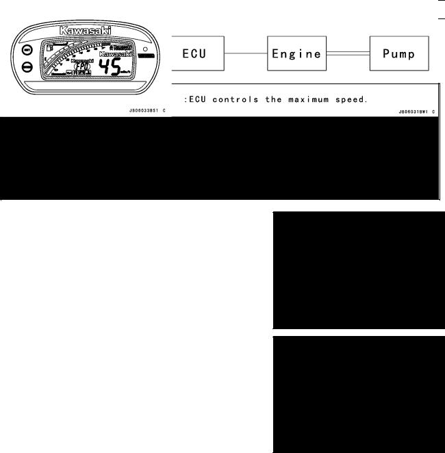
This watercraft is equipped with the Smart Learning Operation mode (SLO) and normal operation mode (Full Power Operation, FPO). The SLO mode reduces the maximum watercraft speed by approximately 30 percent for a use by unskilled operators. To change the SLO mode to FPO mode, and back again, push the “MODE” button for 7 seconds or more.
SLO mode is displayed on the meter as SLO.
NOTE
○When shifted to the SLO mode, the initial display, as shown when the ignition switch is turned on, is shown together with a buzzer sound.
○Then, “SLO” is shown blinking at every three seconds. ○Under the SLO mode, all the meter displays and other functions work in the same manner as the normal oper-
ation (Full Power Operation, FPO) mode.
Normal operation mode (Full Power Operation mode, FPO) is shown by FPO display.
NOTE
○When shifted to the normal operation mode (Full Power Operation mode, FPO), the same initial display is first shown and followed by “FPO” for two seconds. However, “FPO” is shown only once when shifted and is not displayed thereafter.
○When the ignition switch is turned off and on again, the same mode when turned off is displayed again.
GENERAL INFORMATION 1-3
Before Servicing
Before starting to perform an inspection service or carry out a disassembly and reassembly operation on watercraft, read the precautions given below. To facilitate actual operations, notes, illustrations, photographs, cautions, and detailed descriptions have been included in each chapter wherever necessary. This section explains the items that require particular attention during the removal and reinstallation or disassembly and reassembly of general parts.
Especially note the following:
Kawasaki Diagnostic System (KDS) Software
KDS software version 2.2 that runs on Windows personal computer (PC) will be available as a diagnostic tool for watercraft with Kawasaki DFI system.
You need the following items to use the KDS.
Item |
P/No. |
KDS Software Version 2.2 (CD-ROM) |
57001-1503 |
Signal Converter |
57001-1504 |
Communication Cable and Cable Adapter |
57001-1470 |
Relay Cable |
57001-1535 |
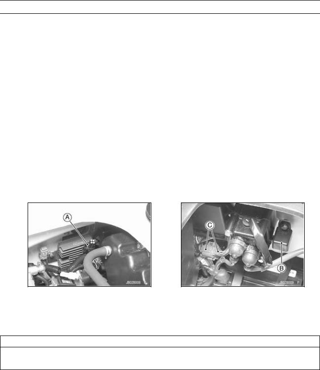
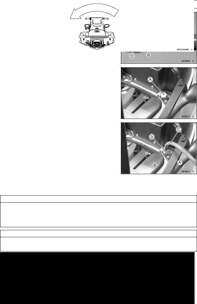
The connectors for the communication cable and relay cable are located in the front of the battery. Connect the communication cable to the KDS connector (4-pin) [A] and the relay cable between the relay assembly [B] connectors (8-pin) [C].
Adjustments
Adjustments shall be made in accordance with the Periodic Maintenance Chart or whenever troubleshooting or presence of symptoms indicate that adjustments may be required. Whenever running of the engine is required during maintenance it is best to have the watercraft in water.
CAUTION
Do not run the engine without cooling water supply for more than 15 seconds, especially in high revolutionary speed or severe engine and exhaust system damage will occur.
Auxiliary Cooling
An auxiliary cooling supply may be used if the watercraft cannot be operated in water during adjustments. If possible, always operate the watercraft in water rather than use an auxiliary cooling supply.
1-4 GENERAL INFORMATION
Before Servicing
•Obtain a standard garden hose [A] and a garden hose adapter [B] as shown.
C:Garden Hose Fitting of Adapter
D:Flushing Fitting of Adapter
E:Thread: Rp 3/4
○Optional part (P/No. 92005-3746) is available as a garden hose adapter.
•Open the front storage compartment cover.
•Remove the flushing cap [A] on the brim of the storage compartment.
•Screw[B]. a garden hose adapter [A] onto the flushing fitting
•Attach a garden hose [C] to a garden hose adapter and secure the hose clamp [D].
•Attach the garden hose to a faucet. Do not turn on the water until the engine is running and turn it off immediately when the engine stops. The engine requires 2.4 L/min (2.5 qts/min) at 1 800 rpm and 7.0 L/min (7.4 qts/min) at 6 000 rpm.
CAUTION
Insufficient cooling supply will cause the engine and/or exhaust system to overheat and severe damage will occur. Excessive cooling supply may kill the engine and flood the cylinders, causing hydraulic lock. Hydraulic lock will cause severe damage to the engine. If the engine dies while using an auxiliary cooling supply, the water must be shut off immediately.
CAUTION
Always turn the boat on its left side. Rolling to the right side can cause water in the exhaust system to run into the engine, with possible engine damage.
GENERAL INFORMATION 1-5
Before Servicing
CAUTION
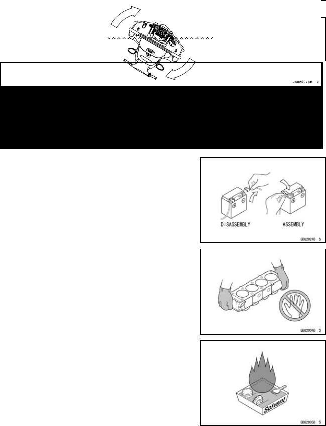
Turn the capsized boat clockwise so that the port side always faces downward. Turning counterclockwise can cause water in the exhaust system to run into the engine, with possible engine damage.
Battery Ground
Before completing any service on the watercraft, disconnect the battery wires from the battery to prevent the engine from accidentally turning over. Disconnect the ground wire
(–) first and then the positive (+). When completed with the service, first connect the positive (+) wire to the positive (+) terminal of the battery then the negative (–) wire to the negative terminal.
Edges of Parts
Lift large or heavy parts wearing gloves to prevent injury from possible sharp edges on the parts.
Solvent
Use a high flush point solvent when cleaning parts. High flush point solvent should be used according to directions of the solvent manufacturer.
1-6 GENERAL INFORMATION
Before Servicing
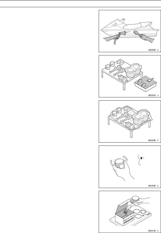
Cleaning Watercraft before Disassembly
Clean the watercraft thoroughly before disassembly. Dirt or other foreign materials entering into sealed areas during watercraft disassembly can cause excessive wear and decrease performance of the watercraft.
Arrangement and Cleaning of Removed Parts
Disassembled parts are easy to confuse. Arrange the parts according to the order the parts were disassembled and clean the parts in order prior to assembly.
Storage of Removed Parts
After all the parts including subassembly parts have been cleaned, store the parts in a clean area. Put a clean cloth or plastic sheet over the parts to protect from any foreign materials that may collect before re-assembly.
Inspection
Reuse of worn or damaged parts may lead to serious accident. Visually inspect removed parts for corrosion, discoloration, or other damage. Refer to the appropriate sections of this manual for service limits on individual parts. Replace the parts if any damage has been found or if the part is beyond its service limit.
Replacement Parts
Replacement Parts must be KAWASAKI genuine or recommended by KAWASAKI. Gaskets, O-rings, Oil seals, Grease seals, circlips or cotter pins must be replaced with new ones whenever disassembled.
GENERAL INFORMATION 1-7
Before Servicing
Assembly Order
In most cases assembly order is the reverse of disassembly, however, if assembly order is provided in this Service Manual, follow the procedures given.
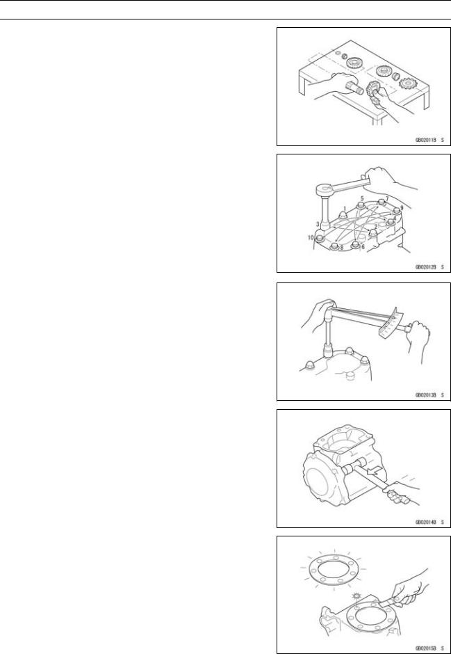
Tightening Sequence
Generally, when installing a part with several bolts, nuts, or screws, start them all in their holes and tighten them to a snug fit. Then tighten them according to the specified sequence to prevent case warpage or deformation which can lead to malfunction. Conversely when loosening the bolts, nuts, or screws, first loosen all of them by about a quarter turn and then remove them. If the specified tightening sequence is not indicated, tighten the fasteners alternating diagonally.
Tightening Torque
Incorrect torque applied to a bolt, nut, or screw may lead to serious damage. Tighten fasteners to the specified torque using a good quality torque wrench.
Force
Use common sense during disassembly and assembly, excessive force can cause expensive or hard to repair damage. When necessary, remove screws that have a non -permanent locking agent applied using an impact driver. Use a plastic-faced mallet whenever tapping is necessary.
Gasket, O-ring
Hardening, shrinkage, or damage of both gaskets and O-rings after disassembly can reduce sealing performance. Remove old gaskets and clean the sealing surfaces thoroughly so that no gasket material or other material remains. Install new gaskets and replace used O-rings when re-assembling
1-8 GENERAL INFORMATION
Before Servicing
Liquid Gasket, Locking Agent
For applications that require Liquid Gasket or a Locking agent, clean the surfaces so that no oil residue remains before applying liquid gasket or locking agent. Do not apply them excessively. Excessive application can clog oil passages and cause serious damage.
Press
For items such as bearings or oil seals that must be pressed into place, apply small amount of oil to the contact area. Be sure to maintain proper alignment and use smooth movements when installing.
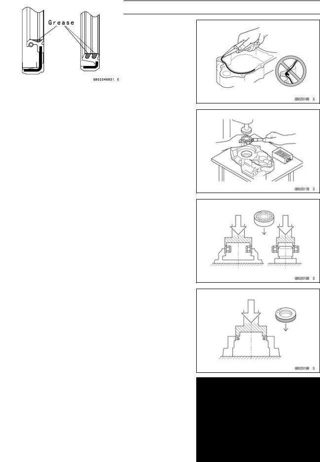
Ball Bearing
Do not remove pressed ball or needle unless removal is absolutely necessary. Replace with new ones whenever removed. Press bearings with the manufacturer and size marks facing out. Press the bearing into place by putting pressure on the correct bearing race as shown.
Pressing the incorrect race can cause pressure between the inner and outer race and result in bearing damage.
Oil Seal, Grease Seal
Do not remove pressed oil or grease seals unless removal is necessary. Replace with new ones whenever removed. Press new oil seals with manufacture and size marks facing out. Make sure the seal is aligned properly when installing.
Apply specified grease to the lip of seal before installing the seal.
GENERAL INFORMATION 1-9
Before Servicing
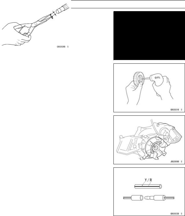
Circlips, Cotter Pins
Replace circlips or cotter pins that were removed with new ones. Take care not to open the clip excessively when installing to prevent deformation.
Lubrication
It is important to lubricate rotating or sliding parts during assembly to minimize wear during initial operation. Lubrication points are called out throughout this manual, apply the specific oil or grease as specified.
Direction of Engine Rotation
When rotating the crankshaft, by hand, the free play amount of rotating direction will affect the adjustment. Rotate the crankshaft to positive direction (counter-clockwise viewed from stern sinde).
Electrical Wires
A two-color wire is identified first by the primary color and then the stripe color. Unless instructed otherwise, electrical wires must be connected to those of the same color.

1-10 GENERAL INFORMATION
Model Identification
JT1500-A1 Left Side View
JT1500-A1 Right Side View
|
GENERAL INFORMATION 1-11 |
General Specifications |
|
|
|
|
|
Items |
JT1500-A1 A2 |
Engine |
|
Type |
4-stroke, DOHC, 4-cylinder, water cooled |
Displacement |
1 498 mL (91.4 cu in.) |
Bore and Stroke |
83 × 69.2 mm (3.27 × 2.72 in.) |
Compression Ratio |
10.6 : 1 |
Maximum Horsepower |
118 kW (160 PS) @7 500 r/min (rpm) |
Maximum Torque |
152 N·m (15.5 kgf·m, 112.1 ft·lb) @7 250 r/min (rpm) |
Ignition System |
Digital transistor |
Lubrication System |
Forced lubrication (semi-dry sump) |
Carburetion System |
FI (fuel injection) MIKUNI AC 60 × 1 |
Starting System |
Electric starter |
Cylinder Numbering Method |
Front (bow) to rear (stern), 1-2-3-4 |
Firing Order |
1-2-4-3 |
Valve Timing: |
|
Inlet: |
|
Open |
22.5° BTDC |
Close |
67.5° ABDC |
Duration |
270° |
Exhaust: |
|
Open |
74.5° BBDC |
Close |
9.5° ATDC |
Duration |
264° |
Tuning Specifications |
|
Spark plug: |
|
Type |
NGK CR9EK |
Gap |
0.7 0.8 mm (0.028 0.031 in.) |
Ignition Timing |
3° ATDC @1 300 r/min 32° BTDC @3 000 r/min (rpm) |
Idle Speed |
1 300 ±100 r/min (rpm) -in water |
|
1 300 ±100 r/min (rpm) -out of water |
Compression Pressure |
1 190 1 799 kPa (12.1 18.3 kgf/cm², 173 261 psi) @430 |
|
r/min (rpm) |
Drive System |
|
Coupling |
Direct drive from engine |
Jet Pump: |
|
Type |
Axial flow single stage |
Thrust |
4 250 N (434 kgf, 955 lb) |
Steering |
Steerable nozzle |
Braking |
Water drag |
Performance |
|
†Minimum Turning Radius |
4.0 m (13.1 ft) |
†Fuel Consumption |
43 L/h (11.4 US gal/h) @full throttle |
†Cruising Range |
134 km (87 mile) @full throttle 1 hour and 26 minutes (3 person) |
Dimensions |
|
Overall Length |
3 120 mm (122.8 in.) |

1-12 GENERAL INFORMATION
General Specifications
Items |
|
JT1500-A1 A2 |
Overall Width |
1 180 mm (46.5 in.) |
|
Overall Height |
1 050 mm (41.3 in.) |
|
Dry Weight |
338 kg (745 lb) |
|
Fuel Tank Capacity |
62 |
L (16.4 US gal) |
Engine Oil |
|
|
Type |
API SE, SF or SG |
|
|
API SH or SJ with JASO MA |
|
Viscosity |
SAE 10W-40 |
|
Capacity |
5.0 L (5.3 US qt) |
|
Electrical Equipment |
|
|
Battery |
12 |
V 18 Ah |
Maximum Generator Output |
16 |
A @14 V |
†: This information shown here represents results under controlled conditions, and the information may not be correct under other conditions.
Specifications subject to change without notice, and may not apply to every country.
GENERAL INFORMATION 1-13
Unit Conversion Table
Prefixes for Units |
Units of Length |
Prefix |
Symbol |
|
Power |
||
mega |
M |
× 1 000 |
000 |
||
kilo |
k |
× |
1 000 |
|
|
centi |
c |
× |
0.01 |
|
|
milli |
m |
|
|
0.001 |
|
|
× |
|
|||
micro |
µ |
|
× 0.000001 |
||
Units of Mass
kg |
× |
2.205 |
= |
lb |
g |
× |
0.03527 |
= |
oz |
km |
× |
0.6214 |
= |
mile |
m |
× |
3.281 |
= |
ft |
mm |
× |
0.03937 |
= |
in. |
Units of Torque
N·m |
× |
0.1020 |
= |
kgf·m |
N·m |
× |
0.7376 |
= |
ft·lb |
N·m |
× |
8.851 |
= |
in·lb |
kgf·m |
× |
9.807 |
= |
N·m |
kgf·m |
× |
7.233 |
= |
ft·lb |
kgf·m |
× |
86.80 |
= |
in·lb |
Units of Volume |
|
|
|
Units of Pressure |
|
|
||||
|
|
|
kPa |
× |
0.01020 |
= |
kgf/cm² |
|||
L |
× |
0.2642 |
= |
gal (US) |
|
kPa |
× |
0.1450 |
= |
psi |
L |
× |
0.2200 |
= |
gal (imp) |
|
kPa |
× |
0.7501 |
= |
cmHg |
L |
× |
1.057 |
= |
qt (US) |
|
kgf/cm² |
× |
98.07 |
= |
kPa |
L |
× |
0.8799 |
= |
qt (imp) |
|
kgf/cm² |
× |
14.22 |
= |
psi |
L |
× |
2.113 |
= |
pint (US) |
|
cmHg |
× |
1.333 |
= |
kPa |
L |
× |
1.816 |
= |
pint (imp) |
|
|
|
|
|
|
mL |
× |
0.03381 |
= |
oz (US) |
|
Units of Speed |
|
|
||
mL |
× |
0.02816 |
= |
oz (imp) |
|
km/h |
× |
0.6214 |
= |
mph |
mL |
× |
0.06102 |
= |
cu in |
|
|
|
|
|
|
Units of Force |
|
|
|
Units of Power |
|
|
||||
|
|
|
kW |
× |
1.360 |
= |
PS |
|||
N |
× |
0.1020 |
= |
kg |
|
kW |
× |
1.341 |
= |
HP |
N |
× |
0.2248 |
= |
lb |
|
|
|
|
|
|
|
PS |
× |
0.7355 |
= |
kW |
|||||
kg |
× |
9.807 |
= |
N |
|
PS |
× |
0.9863 |
= |
HP |
kg |
× |
2.205 |
= |
lb |
|
|
|
|
|
|
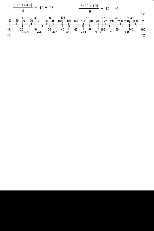
Units of Temperature

PERIODIC MAINTENANCE 2-1
Periodic Maintenance
Table of Contents |
|
2 |
|
|
|
|
|
Periodic Maintenance Chart ................................................................................................... |
2-2 |
|
|
Torque and Locking Agent...................................................................................................... |
2-3 |
|
|
Specifications ......................................................................................................................... |
2-8 |
|
|
Special Tools and Sealant ...................................................................................................... |
2-9 |
|
|
Periodic Maintenance Procedures.......................................................................................... |
2-10 |
|
|
Fuel System......................................................................................................................... |
2-10 |
|
|
Throttle Control System Inspection................................................................................... |
2-10 |
|
|
Air Filter Drain Caps Inspection and Cleaning .................................................................. |
2-10 |
|
|
Air Filter Inspection and Cleaning ..................................................................................... |
2-11 |
|
|
Fuel Vent Check Valve Inspection .................................................................................... |
2-11 |
|
|
Fuel Pump Screen Cleaning ............................................................................................. |
2-12 |
|
|
Throttle Shaft Spring Inspection........................................................................................ |
2-12 |
|
|
Engine Lubrication System .................................................................................................. |
2-12 |
|
|
Engine Oil Change............................................................................................................ |
2-12 |
|
|
Oil Filter Replace .............................................................................................................. |
2-14 |
|
|
Engine Top End ................................................................................................................... |
2-15 |
|
|
Air Suction Valve Inspection ............................................................................................. |
2-15 |
|
|
Valve Clearance Inspection .............................................................................................. |
2-15 |
|
|
Engine Mounting Bolts Inspection and Tightness ............................................................. |
2-19 |
|
|
Engine Bottom End.............................................................................................................. |
2-19 |
|
|
Coupling Damper Inspection............................................................................................. |
2-19 |
|
|
Cooling and Bilge Systems.................................................................................................. |
2-19 |
|
|
Cooling System Flushing .................................................................................................. |
2-19 |
|
|
Bilge System Flushing ...................................................................................................... |
2-21 |
|
|
Pump and Impeller............................................................................................................... |
2-22 |
|
|
Impeller Inspection............................................................................................................ |
2-22 |
|
|
Steering ............................................................................................................................... |
2-22 |
|
|
Steering Cable/Shift Cable Inspection .............................................................................. |
2-22 |
|
|
Handlebar Pivot Lubrication.............................................................................................. |
2-22 |
|
|
Hull/Engine Hood................................................................................................................. |
2-23 |
|
|
Drain Plug Inspection........................................................................................................ |
2-23 |
|
|
Electrical System ................................................................................................................. |
2-23 |
|
|
Battery Charging Condition Inspection ............................................................................. |
2-23 |
|
|
Battery Terminals Inspection............................................................................................. |
2-23 |
|
|
Spark Plug Cleaning and Inspection................................................................................. |
2-24 |
|
|
Lubrication ........................................................................................................................... |
2-24 |
|
|
All Hoses, Hose Clamps, Nuts, Bolts and Fasteners Check ............................................... |
2-27 |
|
|
Nuts, Bolts, and Fasteners Tightness Inspection.............................................................. |
2-27 |
|
|
Hose and Hose Connect Inspection ................................................................................. |
2-27 |
|
|
Rubber Strap Inspection ................................................................................................... |
2-29 |
|
|

2-2 PERIODIC MAINTENANCE
Periodic Maintenance Chart
The scheduled maintenance must be done in accordance with this chart to keep the watercraft in good running condition. The initial maintenance is vitally important and must not be neglected.
Frequency |
Initial 10 |
Every 25 |
Every 50 |
Every 100 |
Refer- |
Description |
Hours |
Hours |
Hours |
Hours |
ence |
Inspect throttle control system (e) |
|
• |
|
|
2-10 |
Inspect/clean air filter drain caps |
|
• |
|
|
2-10 |
|
|
|
|
|
|
Inspect/clean air filter |
|
|
• |
|
2-11 |
|
|
(or every |
|
||
|
|
|
year) |
|
|
Inspect fuel vent check valve |
|
• |
|
|
2-11 |
|
|
|
|
|
|
Clean fuel pump screen (e) |
|
• |
|
|
2-12 |
|
|
|
|
|
|
Inspect throttle shaft spring (replace |
|
|
|
• |
2-12 |
throttle body if necessary) (e) |
|
|
|
||
|
|
|
|
||
Replace engine oil |
|
|
• |
|
2-12 |
|
|
(or every |
|
||
|
|
|
year) |
|
|
Replace engine oil filter |
|
|
|
• |
2-14 |
|
|
|
|
|
|
Check air suction valve |
|
|
|
• |
2-15 |
|
|
|
|
|
|
Inspect/adjust valve clearance (e) |
|
|
|
• |
2-15 |
Inspect/tighten engine mounting bolts |
|
|
• |
|
2-19 |
|
|
(or every |
|
||
|
|
|
year) |
|
|
Inspect/replace coupling damper |
|
|
|
• |
2-19 |
|
|
|
|
|
|
Flush cooling system (after each use in |
|
• |
|
|
2-19 |
salt water) |
|
|
|
||
|
|
|
|
||
Flush bilge line and filter |
|
• |
|
|
2-21 |
|
|
|
|
|
|
Inspect impeller blades for damage |
|
|
|
• |
2-22 |
(remove) |
|
|
|
||
|
|
|
|
||
Inspect steering cable/shift cable |
|
|
|
• |
2-22 |
|
|
|
|
|
|
Lubricate handlebar pivot (disassemble) |
|
• |
|
|
2-22 |
|
|
|
|
|
|
Inspect hull drain screws (replace if |
|
|
• |
|
2-23 |
necessary) |
|
|
|
||
|
|
|
|
||
Inspect battery charging condition |
|
• |
|
|
2-23 |
|
|
|
|
|
|
Inspect battery terminals |
|
• |
|
|
2-23 |
|
|
|
|
|
|
Clean and gap spark plugs (replace if |
|
• |
|
|
2-24 |
necessary) (e) |
|
|
|
||
|
|
|
|
||
Lubricate throttle cable fitting at throttle |
|
• |
|
|
2-24 |
body |
|
|
|
||
|
|
|
|
||
Lubricate throttle cable and throttle fitting |
|
• |
|
|
2-24 |
at throttle case |
|
|
|
||
|
|
|
|
||
Lubricate steering cable/shift cable ball |
|
• |
|
|
|
joints and steering nozzle/reverse bucket |
|
|
|
2-24 |
|
pivots |
|
|
|
|
|
|
|
|
|
|
|
Check all hoses, hose clamps, nuts, |
• |
• |
|
|
2-27 |
bolts, and fasteners |
|
|
|||
|
|
|
(e): Emission Related Items

PERIODIC MAINTENANCE 2-3
Torque and Locking Agent
The following table list the tightening torque for the major fasteners, and the parts requiring use of a non-permanent locking agent or silicone sealant.
Letters used in the “Remarks” column mean:
EO: Apply oil to the threads and seating surface.
L:Apply a non-permanent locking agent to the threads. MO: Apply molybdenum disulfide grease oil solution.
R:Replacement Part
S:Tighten the fasteners following the specified sequence.
SS:Apply silicone sealant to the threads.
Fastener |
|
Torque |
|
|
Remarks |
|
N·m |
kgf·m |
ft·lb |
||||
|
|
|||||
Fuel System |
|
|
|
|
|
|
Vehicle-down Sensor Mounting Screws |
1.5 |
0.15 |
13 |
in·lb |
|
|
Bracket Mounting Bolts |
– |
– |
|
– |
L |
|
Inlet Manifold Mounting Bolts |
25 |
2.5 |
|
18 |
L |
|
Inlet Manifold Mounting Nuts |
20 |
2.0 |
|
14 |
|
|
Delivery Pipe Mounting Bolts |
7.8 |
0.80 |
69 |
in·lb |
|
|
Inlet Air Pressure Sensor Bolts |
7.8 |
0.80 |
69 |
in·lb |
|
|
Throttle Cable Holder Bolts |
8.8 |
0.90 |
78 |
in·lb |
L |
|
Inlet Air Temperature Sensor |
20 |
2.0 |
|
14 |
|
|
Throttle Body Assy Mounting Bolts |
20 |
2.0 |
|
14 |
|
|
Inlet Manifold Drain Plug |
20 |
2.0 |
|
14 |
|
|
Inlet Manifold Plate Bolts |
7.8 |
0.80 |
69 |
in·lb |
|
|
Crankshaft Sensor Screws |
4.4 |
0.45 |
39 |
in·lb |
L |
|
Camshaft Position Sensor Bolt |
7.8 |
0.80 |
69 |
in·lb |
L |
|
Oil Temperature Sensor |
15 |
1.5 |
|
11 |
see text |
|
Water Temperature Sensor |
15 |
1.5 |
|
11 |
see text |
|
Regulator/Rectifier Bolts |
7.8 |
0.80 |
69 |
in·lb |
|
|
ECU Mounting Bolts |
8.8 |
0.90 |
78 |
in·lb |
L |
|
Throttle Sensor Mounting Screws |
2.0 |
0.20 |
18 |
in·lb |
|
|
ISC Actuator Mounting Bolts |
4.9 |
0.50 |
43 |
in·lb |
|
|
Oil Pressure Switch |
15 |
1.5 |
|
11 |
SS |
|
Fuel Filler Tube Clamp Screws |
2.9 |
0.30 |
26 |
in·lb |
|
|
Fuel Level Sensor Clamp Screw |
2.9 |
0.30 |
26 |
in·lb |
|
|
Fuel Filter Mounting Bolts |
8.8 |
0.90 |
78 |
in·lb |
L |
|
Air Filter Mounting Bolts |
9.8 |
1.0 |
87 |
in·lb |
|
|
Air Filter Bracket Mounting Bolts |
7.8 |
0.80 |
69 |
in·lb |
L |
|
Throttle Cable Locknut |
7.8 |
0.80 |
69 |
in·lb |
|
|
Throttle Case Mounting Screws |
3.9 |
0.40 |
35 |
in·lb |
|
|
Engine Lubrication System |
|
|
|
|
|
|
Breather Plate Bolts |
7.8 |
0.80 |
69 |
in·lb |
|
|
Oil Filler Cap |
1.0 |
0.10 |
8.7 in·lb |
|
||
Oil Passage Plugs |
20 |
2.0 |
|
14 |
L |
|
Oil Separator Tank Mounting Screws |
4.9 |
0.50 |
43 |
in·lb |
L |
|
Breather Case Mounting Bolts |
7.8 |
0.80 |
69 |
in·lb |
|
|
Breather Pipe Bolts |
8.8 |
0.90 |
78 |
in·lb |
|
|

2-4 PERIODIC MAINTENANCE
Torque and Locking Agent
Fastener |
|
Torque |
|
|
Remarks |
|
N·m |
kgf·m |
ft·lb |
||||
|
|
|||||
Oil Passage Joints |
11 |
1.1 |
95 |
in·lb |
L |
|
Oil Cooler Assembly Bolts |
7.8 |
0.80 |
69 |
in·lb |
|
|
Oil Pressure Switch |
15 |
1.5 |
|
11 |
SS |
|
Oil Passage Bolt |
78 |
8.0 |
|
58 |
S |
|
Oil Filter |
18 |
1.8 |
|
13 |
EO |
|
Oil Cooler Positioning Bolt |
20 |
2.0 |
|
14 |
S |
|
Oil Pan Bolts |
7.8 |
0.80 |
69 |
in·lb |
S |
|
Dipstick Tube Bolts |
7.8 |
0.80 |
69 |
in·lb |
L, S |
|
Oil Pump Sprocket Bolt |
15 |
1.5 |
|
11 |
L |
|
Oil Pump Cover Bolts |
7.8 |
0.80 |
69 |
in·lb |
|
|
Oil Pressure Relief Valve |
15 |
1.5 |
|
11 |
L |
|
Oil Pipe Bolts |
7.8 |
0.80 |
69 |
in·lb |
|
|
Chain Guide Spring Plate Bolt |
7.8 |
0.80 |
69 |
in·lb |
|
|
Oil Pump Body Plug |
20 |
2.0 |
|
14 |
L |
|
Oil Pump Body Bolts |
7.8 |
0.80 |
69 |
in·lb |
|
|
Oil Screen Bolts |
7.8 |
0.80 |
69 |
in·lb |
|
|
Water Pipe Joints |
20 |
2.0 |
|
14 |
L |
|
Exhaust System |
|
|
|
|
|
|
Exhaust Manifold Mounting Nuts |
25 |
2.5 |
|
18 |
S |
|
Exhaust Manifold Mounting Bolts |
25 |
2.5 |
|
18 |
L, S |
|
Bypass Nozzle |
– |
– |
|
– |
L |
|
Flushing Hose Joint |
11 |
1.1 |
95 |
in·lb |
SS |
|
Water Hose Joint |
11 |
1.1 |
95 |
in·lb |
SS |
|
Water Temperature Sensor |
15 |
1.5 |
|
11 |
see chapter 3 |
|
Exhaust Pipe Mounting Plate Bolts |
30 |
3.0 |
|
22 |
L |
|
Exhaust Pipe Mounting Bolts |
30 |
3.0 |
|
22 |
|
|
Engine Top End |
|
|
|
|
|
|
Air Suction Valve Cover Bolts |
9.8 |
1.0 |
87 |
in·lb |
|
|
Cylinder Head Cover Bolts |
9.8 |
1.0 |
87 |
in·lb |
|
|
Upper Camshaft Chain Guide Bolts |
12 |
1.2 |
104 in·lb |
S |
||
Camshaft Cap Bolts |
12 |
1.2 |
104 in·lb |
S |
||
Cylinder Head Bolts (M7) |
20 |
2.0 |
|
14 |
S |
|
Cylinder Head Bolts (M11) |
23 |
2.3 |
|
17 |
First, MO, S |
|
Cylinder Head Bolts (M11) |
59 |
6.0 |
|
43 |
Final, MO, S |
|
Water Jacket Plugs |
20 |
2.0 |
|
14 |
L |
|
Cylinder Head Bolts (M6) |
12 |
1.2 |
104 in·lb |
S |
||
Engine Hook Bolts |
20 |
2.0 |
|
14 |
|
|
Camshaft Position Sensor Bolt |
9.8 |
1.0 |
87 |
in·lb |
L |
|
Exhaust Side Camshaft Chain Guide Bolts |
25 |
2.5 |
|
18 |
|
|
(Upper) |
|
|
|
|
|
|
Exhaust Side Camshaft Chain Guide Bolts |
12 |
1.2 |
104 in·lb |
|
||
(Lower) |
|
|
|
|
|
|
Upper Camshaft Chain Guide Bolts |
12 |
1.2 |
104 in·lb |
S |
||

PERIODIC MAINTENANCE 2-5
Torque and Locking Agent
Fastener |
|
Torque |
|
|
Remarks |
|
N·m |
kgf·m |
ft·lb |
||||
|
|
|||||
Inlet Side Camshaft Chain Guide Bolts |
12 |
1.2 |
104 in·lb |
L |
||
Camshaft Chain Tensioner Mounting Bolts |
9.8 |
1.0 |
87 |
in·lb |
L |
|
Camshaft Chain Tensioner Cap Bolt |
20 |
2.0 |
|
14 |
|
|
Camshaft Position Sensor Rotor Bolt |
12 |
1.2 |
104 in·lb |
L |
||
Water Hose Joint |
11 |
1.1 |
95 |
in·lb |
SS |
|
Oil Passage Joint |
11 |
1.1 |
95 |
in·lb |
L |
|
Engine Removal/Installation |
|
|
|
|
|
|
Engine Mounting Bolts |
36 |
3.7 |
|
27 |
L |
|
Engine Damper Mounting Bolts |
16 |
1.6 |
|
12 |
L |
|
Engine Bottom End |
|
|
|
|
|
|
Crankshaft Sensor Cover Bolts |
7.8 |
0.80 |
69 |
in·lb |
|
|
Engine Bracket Mounting Bolts |
29 |
3.0 |
|
22 |
L |
|
Timing Rotor Bolt |
29 |
3.0 |
|
22 |
L |
|
Connecting Rod Nuts |
– |
– |
|
– |
MO, see text |
|
Oil Passage Plugs |
20 |
2.0 |
|
14 |
L |
|
Stator Mounting Bolts |
12 |
1.2 |
104 in·lb |
L |
||
Grommet Cover Bolts |
9.8 |
1.0 |
87 |
in·lb |
L |
|
Magneto Cover Bolts |
20 |
2.0 |
|
14 |
|
|
Output Cover Bolts |
7.8 |
0.80 |
69 |
in·lb |
|
|
Output Shaft |
245 |
25 |
180 |
MO |
||
Coupling |
98 |
10 |
|
72 |
|
|
Crankcase Bolts (M10) |
50 |
5.0 |
|
36 |
MO, S |
|
Crankcase Bolts (M8) |
29 |
3.0 |
|
22 |
MO, S |
|
Crankcase Bolts (M8) |
29 |
3.0 |
|
22 |
S |
|
Crankcase Bolts (M6) |
12 |
1.2 |
104 in·lb |
S |
||
Cooling and Bilge Systems |
|
|
|
|
|
|
Breather Mounting Bolt |
– |
– |
|
– |
L |
|
Water Hose Joint (L Shape Type) |
11 |
1.1 |
95 |
in·lb |
SS |
|
Water Hose Joint (Straight Shape Type) |
20 |
2.0 |
|
14 |
SS |
|
Water Hose Joint (Straight Shape Type) |
11 |
1.1 |
95 |
in·lb |
SS, see text |
|
Drive System |
|
|
|
|
|
|
Coupling |
39 |
4.0 |
|
29 |
L |
|
Drive Shaft Holder Mounting Bolts |
22 |
2.2 |
|
16 |
L |
|
Coupling Cover Bolts |
8.8 |
0.90 |
78 |
in·lb |
L |
|
Pump and Impeller |
|
|
|
|
|
|
Steering Nozzle Pivot Bolts |
19 |
1.9 |
|
14 |
L |
|
Pump Mounting Bolts |
36 |
3.7 |
|
27 |
L |
|
Pump Outlet Mounting Bolts |
19 |
1.9 |
|
14 |
L |
|
Pump Cap Bolts |
9.8 |
1.0 |
87 |
in·lb |
L |
|
Pump Cap Plug |
3.9 |
0.40 |
35 in·lb |
|
||
Impeller |
98 |
10 |
|
72 |
|
|
Pump Bracket Mounting Bolts (2) |
19 |
1.9 |
|
14 |
L, SS |
|
Pump Bracket Mounting Bolts (4) |
9.8 |
1.0 |
87 |
in·lb |
L |
|

2-6 PERIODIC MAINTENANCE
Torque and Locking Agent
Fastener |
|
Torque |
|
|
Remarks |
|
N·m |
kgf·m |
ft·lb |
||||
|
|
|||||
Pump Cover Mounting Bolts |
7.9 |
0.80 |
69 |
in·lb |
L |
|
Grate Mounting Bolts |
9.8 |
1.0 |
87 |
in·lb |
L |
|
Filter Cover Mounting Bolts |
9.8 |
1.0 |
87 |
in·lb |
L |
|
Steering |
|
|
|
|
|
|
Handlebar Clamp Bolts |
16 |
1.6 |
|
12 |
L |
|
Start/stop Switch Case Mounting Screws |
3.9 |
0.40 |
35 |
in·lb |
|
|
Throttle Case Mounting Screws |
3.9 |
0.40 |
35 |
in·lb |
|
|
Steering Shaft Locknut |
49 59 |
5.0 6.0 |
36 43 |
|
||
Steering Shaft Nut |
– |
– |
|
– |
Hand-Tight |
|
Steering Holder Mounting Bolts |
20 |
2.0 |
14.5 |
L |
||
Steering Neck Mounting Bolts |
16 |
1.6 |
|
12 |
L |
|
Steering Cable Joint Bolt |
9.8 |
1.0 |
87 |
in·lb |
L |
|
Ball Joint |
9.8 |
1.0 |
87 |
in·lb |
L |
|
Shift Cable End Nut |
9.8 |
1.0 |
87 |
in·lb |
|
|
Reverse Bucket Pivot Bolts |
19 |
1.9 |
|
14 |
L |
|
Shift Cable Nut |
39 |
4.0 |
|
29 |
|
|
Steering Cable Nut |
39 |
4.0 |
|
29 |
|
|
Shift Lever Locknut |
20 |
2.0 |
14.5 |
|
||
Hull/Engine Hood |
|
|
|
|
|
|
Crossmember Bolts |
7.8 |
0.80 |
69 |
in·lb |
L |
|
Handrail Bolts |
9.8 |
1.0 |
87 |
in·lb |
L |
|
Lock Assembly Nut |
4.9 |
0.50 |
43 |
in·lb |
|
|
Front Duct Bolts |
– |
– |
|
– |
L |
|
Damper Bolts |
– |
– |
|
– |
L |
|
Damper Bracket Bolts |
– |
– |
|
– |
L |
|
Front Storage Compartment Cover Bolts |
– |
– |
|
– |
L |
|
Hinge Bolts |
– |
– |
|
– |
L |
|
Front Storage Compartment Hook Bolts |
– |
– |
|
– |
L |
|
Steering Cover Bolts |
– |
– |
|
– |
L |
|
Meter Screen Bolts |
– |
– |
|
– |
L |
|
Seat Hook Bolts |
– |
– |
|
– |
L |
|
Seat Locknut |
– |
– |
|
– |
L |
|
Reboarding Step Bolts |
– |
– |
|
– |
L |
|
Mirror Stay Bolts |
– |
– |
|
– |
L |
|
Stabilizer Bolts |
9.8 |
1.0 |
87 |
in·lb |
L |
|
Air inlet Duct Bolts |
– |
– |
|
– |
L |
|
Exhaust Outlet Bolts |
– |
– |
|
– |
L |
|
Electrical System |
|
|
|
|
|
|
Vehicle-Down Sensor Mounting Screws |
1.5 |
0.15 |
13 |
in·lb |
|
|
Electrical Parts Bracket Screws |
4.9 |
0.50 |
43 |
in·lb |
L |
|
Starter Relay Case Bolts |
7.8 |
0.80 |
69 |
in·lb |
|
|
Ignition Coil Mounting Bolts |
8.8 |
0.90 |
78 |
in·lb |
L |
|
Water Temperature Sensor |
15 |
1.5 |
|
11 |
see text |
|
Loading...