


Kawasak
D SERIES CONTROLLER
TROUBLESHOOTING AND
COMPONENT REPLACEMENT
MPVDCONTV113E-3
 Kawasak
Kawasaki Robotics (USA), Inc.
This publication contains proprietary information of Kawasaki Robotics (USA), Inc. and is furnished solely for customer use only. No other uses are authorized or permitted without the express written permission of Kawasaki Robotics (USA), Inc. The contents of this manual cannot be reproduced, nor transmitted by any means, e.g., mechanical, electrical, photocopy, facsimile, or electronic data media, without the express written permission of Kawasaki Robotics (USA), Inc.
All Rights Reserved.
Copyright © 2001, Kawasaki Robotics (USA), Inc.
Wixom, Michigan 48393
The descriptions and specifications in this manual were in effect when it was submitted for publishing. Kawasaki Robotics (USA), Inc. reserves the right to change or discontinue specific robot models and associated hardware and software, designs, descriptions, specifications, or performance parameters at any time and without notice, without incurring any obligation whatsoever.
This manual presents information specific to the robot model listed on the title page of this document. Before performing maintenance, operation, or programming procedures, all personnel are recommended to attend an approved Kawasaki Robotics (USA), Inc. training course.
KAWASAKI ROBOTICS (USA), INC. TRAINING
Training courses covering operation, programming, electrical maintenance, and mechanical maintenance are available from Kawasaki Robotics (USA), Inc. These courses are conducted at our training facility in Wixom, Michigan, or on-site at the customer’s location.
For additional information contact:
Kawasaki Robotics (USA), Inc.
Training and Documentation Dept.
28059 Center Oaks Court
Wixom, Michigan 48393

 Kawasak
D SERIES CONTROLLER TROUBLESHOOTING AND COMPONENT REPLACEMENT
REVISION HISTORY
Revision |
Release |
|
|
Number |
Date |
Description of Change |
Initials |
|
|
|
|
-0 |
11/20/03 |
Initial PDF release, based on Rev.-0 of print copy |
CB/CB |
|
|
|
|
-1 |
4/27/04 |
Revision 1, based on Rev.-1 of print copy |
CB/CB |
|
|
|
|
-3 |
9/06/05 |
Revision 3, based on Rev.-3 of print copy |
CB/CB |
|
|
|
|
|
|
|
|
|
|
|
|
|
|
|
|
|
|
|
|
|
|
|
|

 Kawasak
D SERIES CONTROLLER TROUBLESHOOTING AND COMPONENT REPLACEMENT
|
TROUBLESHOOTING |
|
1.0 |
TROUBLESHOOTING................................................................................... |
1-2 |
1.1 |
Error Recovery ............................................................................................... |
1-2 |
1.2 |
Preliminary Troubleshooting ........................................................................... |
1-5 |
1.2.1 |
Troubleshooting Common Failures................................................................. |
1-5 |
1.2.1.1 |
Controller Power Cannot Be Set to ON .......................................................... |
1-6 |
1.2.1.2 |
Teach Pendant Is Inoperable ......................................................................... |
1-8 |
1.2.1.3 |
Motor Power Cannot Be Enabled ................................................................. |
1-10 |
1.2.1.4 |
Robot Does Not Move .................................................................................. |
1-11 |
1.3 |
Error Codes ................................................................................................. |
1-12 |
1.3.1 |
Error Display ................................................................................................ |
1-13 |
1.3.2 |
Error List ...................................................................................................... |
1-13 |
1.3.2.1 |
DXXXX Fatal Error Codes............................................................................ |
1-14 |
1.3.2.2 |
EXXXX Non-Fatal Error Codes .................................................................... |
1-59 |
1.3.2.3 |
PXXXX Operation Error Codes .................................................................. |
1-159 |
1.3.2.4 |
WXXXX Mechanical/Control Warning Error Codes .................................... |
1-200 |
1.4 |
Troubleshooting Flowcharts ....................................................................... |
1-210 |
August 9, 2005 |
1-1 |

 Kawasak
D SERIES CONTROLLER TROUBLESHOOTING AND COMPONENT REPLACEMENT
TROUBLESHOOTING
1.0 TROUBLESHOOTING
This unit provides error recovery flowcharts, error code information, and error code troubleshooting flow charts. In addition, typical causes and remedies for the errors are also provided.
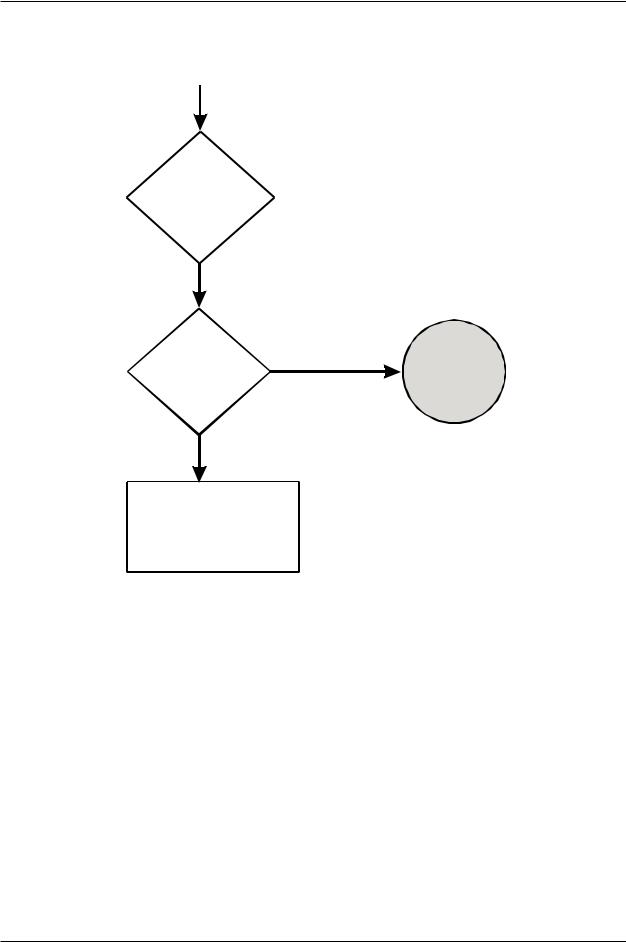
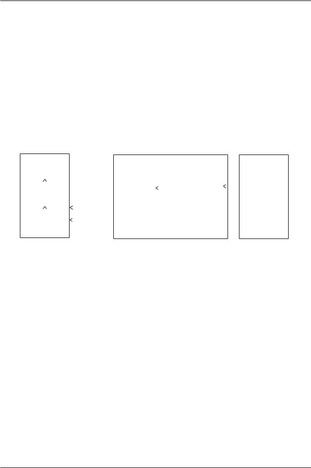
1.1 ERROR RECOVERY
Figures 1-1 and 1-2 show troubleshooting processes that may be helpful if the controller becomes unresponsive to commands or an error code has been encountered that cannot be cleared. Troubleshooting should begin with confirmation of basic integrity of the system: ensure that the power supply is on and meeting supply requirements, all cables are correctly attached, all circuit boards are properly installed and fully seated, all peripheral equipment is wired correctly, software is properly configured, etc.
1-2 |
August 9, 2005 |

 Kawasak
D SERIES CONTROLLER TROUBLESHOOTING AND COMPONENT REPLACEMENT
TROUBLESHOOTING
Locate error on the error |
Source of error known |
Troubleshoot |
|
|
|
table and determine the |
|
Run Program |
|||
|
|
||||
|
and correct |
|
|||
characteristics and possible |
|
|
and continue |
||
causes of the error |
|
source of |
|
to monitor |
|
|
error |
|
|||
|
|
|
|
|
|
|
|
|
|
|
|
|
Source of error unknown |
|
|
|
|
|
|
|
|
|
|
Press the yellow |
Error cleared and robot |
Run Program |
|
runs normally |
|||
reset button on the |
and continue |
||
|
|||
controller panel |
|
to monitor |
Error will not clear or machine is in a “locked” mode
Have any changes been |
|
|
|
Error clears and robot |
|
||||
made to system? New |
|
Ensure the robot |
Run Program |
||||||
Yes |
runs normally |
||||||||
internal parts, interface |
system data, all |
and continue |
|||||||
components added or |
|
components, signals, |
|
|
to monitor |
||||
removed, signal interface |
|
and programs are |
|
|
|
||||
agrees with program, etc. |
|
compatible |
|
|
|
||||
|
|
|
|
|
|
||||
|
|
|
|
|
|
|
|
||
No |
|
|
|
|
|
|
|
|
|
|
|
|
|
|
|
|
|
|
|
Cycle the |
Error or “locked” |
Run Program |
|
condition cleared |
and continue |
||
controller power |
|||
|
to monitor |
||
OFF and ON |
|
||
|
|
Error still present
Create |
Error or “locked” |
Reset |
Run program |
backup information |
condition cleared |
system settings not |
and continue |
files and initialize the |
|
set to defaults after |
to monitor |
system |
|
initialization |
|
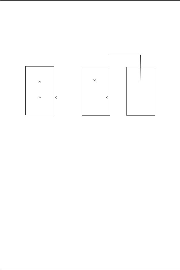
Continued on next page
Figure 1-1 Troubleshooting Process
August 9, 2005 |
1-3 |
 Kawasak
D SERIES CONTROLLER TROUBLESHOOTING AND COMPONENT REPLACEMENT
TROUBLESHOOTING
Continued from previous pg
Error still present
Remove the 1KA board from the rack and allow RAM memory to deplete
Reinstall |
Error clears and robot |
Run program |
|
1KA board, |
runs normally |
||
and continue |
|||
initialize the |
|
||
|
to monitor |
||
system, zero |
|
||
|
|
Begin electrical troubleshooting and repair if qualified; call service technician for further assistance
Figure 1-2 Troubleshooting Process (Continued)
1-4 |
August 9, 2005 |

 Kawasak
D SERIES CONTROLLER TROUBLESHOOTING AND COMPONENT REPLACEMENT
TROUBLESHOOTING
1.2 PRELIMINARY TROUBLESHOOTING
Prior to following error code troubleshooting procedures, ensure preliminary troubleshooting steps are completed.
1.Ensure proper 460 VAC three-phase power is available at the input and output side of the controller main disconnect (circuit breaker F1).
2.Ensure circuit breakers F2, F3, F4, and F5 are not tripped.
3.Ensure proper +5 VDC, +12 VDC, -12 VDC and +24 VDC are available from the AVR power supply.
4.Observe the state of LEDs and refer to the appropriate section of the D Series Controller Electrical Maintenance Manual for conditions indicated by the LEDs. If these conditions are not normal, correct the cause of abnormal LED indications.
5.Check for loose connection at circuits boards and cable connections.
6.Ensure all circuit boards are properly seated in the card rack (where applicable).
7.Ensure the F1 and F2 fuses on the 1KP board are not open.
1.2.1 TROUBLESHOOTING COMMON FAILURES
This section describes some common failures, possible causes, and corrective actions.
1.2.1.1Controller Power Cannot Be Set ON
1.2.1.2Teach Pendant is Inoperable
1.2.1.3Motor Power Cannot Be Set ON
1.2.1.4Robot Does Not Move
August 9, 2005 |
1-5 |

 Kawasak
D SERIES CONTROLLER TROUBLESHOOTING AND COMPONENT REPLACEMENT
TROUBLESHOOTING
1.2.1.1 CONTROLLER POWER CANNOT BE SET TO ON
This failure occurs when the controller does not power-up when the controller main disconnect is set to ON.
Failure 1: When the controller main disconnect is set to ON, circuit breaker F1 is tripped immediately.
Main causes include:
1.The AC power line is short-circuited in the controller, and circuit breaker F1 detects overcurrent and is tripped.
2.Defective F1 circuit breaker.
Interrupt the 460 VAC to the main disconnect (circuit breaker F1) set the controller main disconnect to ON. Using an ohm meter check for a short circuit between these points:
R and S, S and T, T and R, R and FG, S and FG, T and FG (FG=frame ground)
If a short circuit is detected replace components as necessary (wiring, transformer T1, circuit breaker F1, etc.).
Failure 2: When the main disconnect is set to ON, the control power lamp does not illuminate (circuit breaker F1 does not trip).
This failure occurs when the controller does not activate properly because of an abnormality in the primary power supplied to the controller or in the power supply circuit in the controller.
Main causes include:
1.The primary power voltage supplied to the controller is not within specifications, the primary power cable is disconnected or damaged, or the primary power is not supplied.
2.Power is not supplied to the 1KQ/1NR board, or the 1KQ/1NR board is defective.
3.Power is not supplied to the AVR power supply.
4.Power is not supplied to the control power lamp due to a defective AVR power supply, 1KX/1NR board, 1LS/1NS board or control power lamp.
5.Disconnected or short-circuited wiring in the controller.
1-6 |
August 9, 2005 |

 Kawasak
D SERIES CONTROLLER TROUBLESHOOTING AND COMPONENT REPLACEMENT
TROUBLESHOOTING
Ensure primary power supply is within specifications. Ensure primary power supply cable is properly connected and is not damaged.
Ensure connectors at the 1KQ/1NR board are properly installed and not damaged.
Ensure the 1KP board fuses F1 and F2 are not open.
Replace the 1KQ/1NR board.
Ensure the power supplied to the AVR power supply is within specifications. Ensure the power connector at the AVR power supply is properly connected and not damaged.
Ensure to output voltages from the AVR power supply are within specifications.
Ensure the control power lamp is properly installed and is not defective.
Repair or replace disconnected or short-circuited wiring in the controller.
August 9, 2005 |
1-7 |
 Kawasak
D SERIES CONTROLLER TROUBLESHOOTING AND COMPONENT REPLACEMENT
TROUBLESHOOTING
1.2.1.2 TEACH PENDANT IS INOPERABLE
The teach pendant is in operable with the controller main disconnect set to ON and the control power lamp is illuminated.
Failure 1: The control power lamp is illuminated and the teach pendant is inoperable (the back light is not illuminated).
DC power is supplied to the controller, but power is not supplied to the teach pendant to illuminate the display or back light.
Main causes include:
1.+12 VDC is not supplied to the teach pendant.
2.Defective LCD panel, circuit board, or other internal teach pendant components.
3.Disconnected or short-circuited teach pendant cable.
Ensure the teach pendant cable is properly connected to the controller.
Replace the teach pendant.
Replace the teach pendant cable.
Failure 2: The back light is illuminated, but the screen is not displayed.
When the teach pendant back light is illuminated this indicates power is supplied to the teach pendant. If the teach pendant is operating normally the initial screen is displayed regardless of the 1KA board condition.
Main causes include:
1.Defective LCD panel, circuit board, or other internal teach pendant components.
Replace the teach pendant.
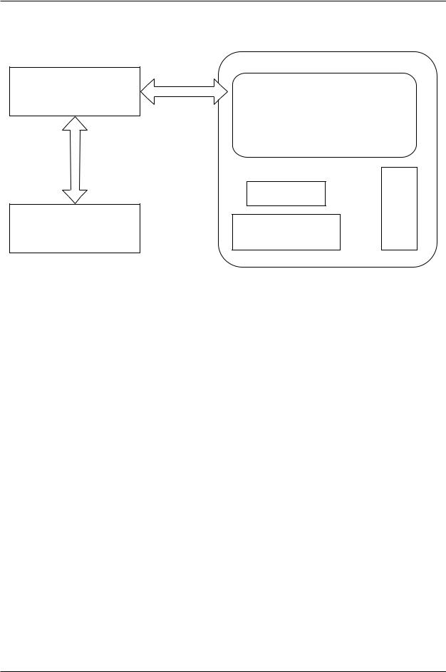
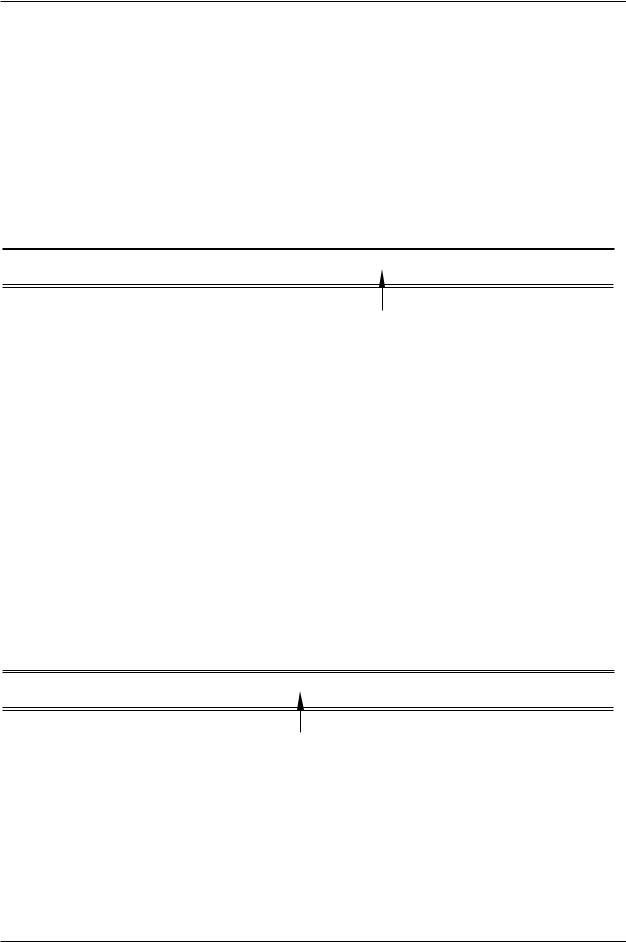
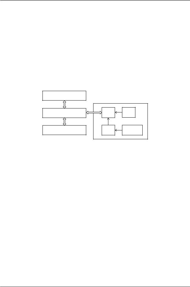
Failure 3: The teach pendant screen is displayed and the back light is illuminated, but key input and AS Language commands are not possible.
This condition occurs when key input and AS Language commands do not reach the
1KA board or data from the 1KA board does not reach the teach pendant.
Data is transmitted between the 1KA board and the teach pendant as shown in figure 1- 3.
1-8 |
August 9, 2005 |
 Kawasak
D SERIES CONTROLLER TROUBLESHOOTING AND COMPONENT REPLACEMENT
TROUBLESHOOTING
1KX/1NX Mother Board
Display Device
Input
Keys
1KA Main CPU Board
Teach Pendant
Figure 1-3 1KA/Teach Pendant Communication
Main causes include:
1.Interruption in data communication between the teach pendant and the 1KA board.
2.Defective LCD panel, circuit board, or other internal teach pendant components.
3.Defective 1KA or 1KX/1NX boards.
4.Disconnected or short-circuited teach pendant cable.
Ensure the teach pendant cable is properly connected to the controller.
Replace the teach pendant cable.
Replace the teach pendant.
Replace the 1KA or 1KX/1NX boards.
August 9, 2005 |
1-9 |

 Kawasak
D SERIES CONTROLLER TROUBLESHOOTING AND COMPONENT REPLACEMENT
TROUBLESHOOTING
1.2.1.3 MOTOR POWER CANNOT BE ENABLED
This condition exists when motor power does not engage when the MOTOR POWER switch is pressed.
Main causes include:
1.An error condition exists.
2.K1, K2, or K3 are not engaged due to a defective 1KQ/1NR board, MC unit, teach pendant, software, eternal signals etc.
3.Emergency stop condition exists.
4.Defective power block.
5.Disconnected or short-circuited motor power supply harness.
6.Motor temperature or controller internal temperature exceeds limits
If the operation panel error lamp is illuminated or an error message is displayed on the teach pendant LCD, take appropriate measures to release the error condition according to the error message.
Check and repair any abnormalities in the motor power supply circuit.
Ensure all EMERGENCY STOP switches are released.
Replace the power block.
Replace the motor power supply harness.
Ensure motor temperature and controller internal temperature does not exceed limits.
1-10 |
August 9, 2005 |
 Kawasak
D SERIES CONTROLLER TROUBLESHOOTING AND COMPONENT REPLACEMENT
TROUBLESHOOTING
1.2.1.4 ROBOT DOES NOT MOVE
This condition exists when the robot does not move when conditions are set for teach or repeat mode.
Main causes include:
1.External hold condition exists.
2.An error condition exists.
3.Operation panel switches set incorrectly.
4.Motor brakes are not released.
5.If the check mode is selected, ensure an enabling device is engaged and the GO
(step forward) key is pressed.
6.Robot is waiting for input signals in repeat mode (cycle start, step forward, program change, WX, JUMP, etc.)
Release external hold condition.
If the operation panel error lamp is illuminated or an error message is displayed on the teach pendant LCD, take appropriate measures to release the error condition according to the error message.
Ensure the operation panel switches are set correctly for robot operation.
Ensure proper brake voltage is available to the brake release circuit. Check and repair poor connections, disconnected connectors, open wiring, short circuited wiring, or any abnormalities in the brake circuits. Ensure the 1KP board, 1KQ/1NR board, AVR power supply, MC unit, 1KQ/1NR board, servo motor, and controller internal brake harnesses are in serviceable condition.
When check mode is selected, ensure an enabling device is engaged and the GO (step forward) key is pressed.
In repeat mode, ensure input signals are received to release a wait condition.
!WARNING
The robot may move suddenly when a wait condition is released. Do not approach the robot when it appears to be stopped.
August 9, 2005 |
1-11 |

 Kawasak
D SERIES CONTROLLER TROUBLESHOOTING AND COMPONENT REPLACEMENT
TROUBLESHOOTING
1.3 ERROR CODES
This unit provides information about the error codes that are displayed on the teach pendant or other user interfaces that provide display screen information. The error codes are listed in numerical order by prefix and code number with the message that is displayed on the teach pendant. An expanded explanation of the message is provided along with possible methods to clear or prevent the specific error. Troubleshooting information is preceded by an symbol.
Table 1-1 provides an explanation of the error code prefixes.
Table 1-1 Error Code Prefix Descriptions
Error Log Code |
Description |
Comment |
|
|
|
D |
Fatal error |
Hardware, software, or peripheral device error. |
|
|
When error is corrected control power must be |
|
|
cycled OFF and ON. |
|
|
|
E |
Non-fatal error |
When error is corrected, press error reset. |
|
|
|
P |
Operation error |
Does not affect robot motion. |
|
|
|
W |
Mechanical/control warning |
May cause an error if not corrected. |
|
|
|
Table 1-2 describes the controller state for each type of error.
Table 1-2 Controller Error State
Error Type |
Error Lamp |
Cycle Start Lamp |
Motor Power |
|
|
|
|
P |
OFF |
ON |
ON |
|
|
|
|
W |
1ON or OFF |
1ON or OFF |
1ON or OFF |
E |
ON |
OFF |
1ON or OFF |
D |
ON |
OFF |
OFF |
|
|
|
|
1Depending on the error content
1-12 |
August 9, 2005 |
 Kawasak
D SERIES CONTROLLER TROUBLESHOOTING AND COMPONENT REPLACEMENT
TROUBLESHOOTING
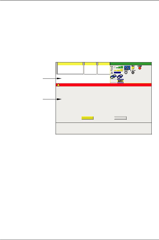
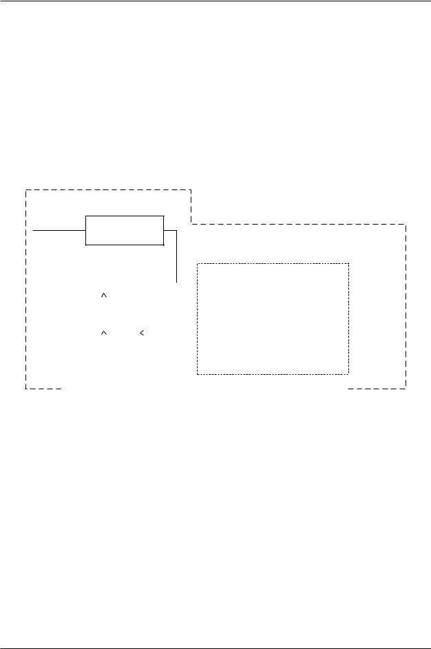
1.3.1 ERROR DISPLAY
Error messages are displayed on the teach pendant LCD screen and/or a PC interfaced with the controller using KRterm/KCWIN32 terminal software.
The teach pendant LCD screen displays operation errors (P errors) in the system message area and other error messages are shown in a pop-up screen display (Figure 1-4).
System Message Area
Error Pop-up Screen
|
Program |
[Comment ] |
Step |
PC |
Status |
03-01-31 11:55 |
||
|
pg6 |
|
1 |
1 pcprg1 |
T |
|
JOINT |
|
|
|
|
|
|
||||
|
[ |
] |
[ |
] |
C |
|
|
|
|
R |
90% |
|
|
||||
Program aborted. No = 1 |
|
|
|
|
|
|||
|
|
|
|
|
|
|||
|
|
|
|
|
R P S |
|
|
|
! |
Error |
|
|
|
|
|
|
|
(E0100) 02-11-08(Fri) 16:33:20 |
|
|
|
|
|
|||
Abnormal comment statement exists. |
|
|
|
|
||||
|
|
|
Reset |
|
|
Close |
|
|
|
JT 1 |
JT 2 |
JT 3 |
JT 4 |
|
JT 5 |
JT 6 |
|
|
0.000 |
0.000 |
0.000 |
0.000 |
|
0.000 |
0.000 |
|
Figure 1-4 Teach Pendant Error Screen Display
1.3.2 ERROR LIST
Refer to the following sections for errors and descriptions:
1.3.2.1DXXXX Fatal Error Codes
1.3.2.2EXXXX Non-Fatal Error Codes
1.3.2.3PXXXX Operation Error Codes
1.3.2.4WXXXX Mechanical/Control Warning Error Codes
August 9, 2005 |
1-13 |
 Kawasak
D SERIES CONTROLLER TROUBLESHOOTING AND COMPONENT REPLACEMENT
TROUBLESHOOTING
1.3.2.1 DXXXX FATAL ERROR CODES
ERROR CODE D0001 |
CPU Error. (PC=XX) |
The 1KA board CPU has stopped (detected by the AS software). This error is caused by defective AS or servo software, defective hardware, or noise related malfunction.
PC Error Display Example:
Error (D0001) CPU error Code=1
Task (Pc01) Stop SIG=00070004 [FAULT (PARALLEL)] PC=*****
Indicates the place the error occurred
Refer to the error message displayed on a PC interfaced with the controller.
Cycle controller power OFF and ON. Do not initialize the controller. If a message for initialization is displayed, select “NO”.
If the error does not reset when power is cycled, initialize the system and reload program data.
Replace the 1KA board.
If the above steps do not correct the error, contact KRI customer service.
_____________________________________________________________________
ERROR CODE D0002 |
Main CPU BUS error. (PC=XX) |
A 1KA board bus error occurs (in the VME bus line, detected by AS software); data processing is not completed normally. This error is caused by defective AS software, defective 1KA board, or noise related malfunction.
PC Error Display Example:
Error (D0002) CPU BUS error Code=1
Task (Pc01) Stop SIG=00070004 [NMI(VME BUS ERROR)] PC=*****
Indicates the place the error occurred
Refer to the error message displayed on a PC interfaced with the controller.
Cycle controller power OFF and ON. Do not initialize the controller. If a message for initialization is displayed, select “NO”.
If the error does not reset when power is cycled, initialize the system and reload program data.
Replace the 1KA board.
If the above steps do not correct the error, contact KRI customer service.
_____________________________________________________________________
1-14 |
August 9, 2005 |
 Kawasak
D SERIES CONTROLLER TROUBLESHOOTING AND COMPONENT REPLACEMENT
TROUBLESHOOTING
ERROR CODE D0003 |
VME BUS error. (PC=XX) |
This error occurs when the CPU does not receive a response from one of the I/O bus devices within a specific time. This error is caused by defective AS software, defective 1KA board, or noise related malfunction.
PC Error Display Example:
Error (D0003) VME bus error Code=1
Task (Pc01) Stop SIG=00070004 [NMI(VME BUS ERROR)] PC=***** bus-read=******** bus-write=*********
Indicates the place the error occurred
Refer to the error message displayed on a PC interfaced with the controller.
Cycle controller power OFF and ON. Do not initialize the controller. If a message for initialization is displayed, select “NO”.
If the error does not reset when power is cycled, initialize the system and reload program data.
Replace the 1KA board.
If the above steps do not correct the error, contact KRI customer service.
_____________________________________________________________________
ERROR CODE D0004 |
[ARM CONTROL BOARD] CPU error. (PC=XX) |
The 1KB board CPU is stopped (detected by the AS software). This error is caused by defective AS or servo software, defective hardware, or noise related malfunction.
PC Error Display Example:
Error (D0004) [ARM CONTROL BOARD] CPU error Code=1
Task (Pc01) Stop SIG=00070004 [FAULT (PARALLEL)] PC=*****
Indicates the place the error occurred
Refer to the error message displayed on a PC interfaced with the controller.
Cycle controller power OFF and ON. Do not initialize the controller. If a message for initialization is displayed, select “NO”.
Ensure the correct 1KB board software is loaded into the 1KA board.
Replace the 1KB board.
If the above steps do not correct the error, contact KRI customer service.
_____________________________________________________________________
August 9, 2005 |
1-15 |
 Kawasak
D SERIES CONTROLLER TROUBLESHOOTING AND COMPONENT REPLACEMENT
TROUBLESHOOTING
ERROR CODE D0005 |
[ARM CONTROL BOARD] CPU BUS error. (PC=XX) |
On the 1KB board, a bus error occurs (in the VME bus line, detected by AS software); data processing is not completed normally. This error is caused by defective AS software, defective 1KB board, or noise related malfunction.
PC Error Display Example:
Error (D0005) [ARM CONTROL BOARD] CPU BUS error Code=1
Task (Pc01) Stop SIG=00070004 [NMI(VME BUS ERROR)] PC=*****
Indicates the place the error occurred
Refer to the error message displayed on a PC interfaced with the controller.
Cycle controller power OFF and ON. Do not initialize the controller. If a message for initialization is displayed, select “NO”.
Ensure the correct 1KB board software is loaded into the 1KA board.
Replace the 1KB board.
If the above steps do not correct the error, contact KRI customer service.
_____________________________________________________________________
ERROR CODE D0900 |
Teach data is broken. |
The program storage area of the system memory is damaged and is not linking data correctly.
Main causes include:
1.Loss of memory battery back-up.
2.Noise related malfunction.
3.Defective 1KA board.
Set the 1KA board switch SW2-8 to ON and initialize the memory, do not use AUX 0805 or SYSINIT command. Reload the robot program data.
Check the memory backup battery. Replace if necessary (3.3 VDC or less). When battery voltage drops to 3.3 VDC, or less, error W1010 is displayed.
Replace the 1KA board if the error recurs.
_____________________________________________________________________
1-16 |
August 9, 2005 |

 Kawasak
D SERIES CONTROLLER TROUBLESHOOTING AND COMPONENT REPLACEMENT
TROUBLESHOOTING
ERROR CODE D0901 AS Flash memory sum check error.
A check sum error occurrs in AS software, in flash memory on the 1KA board, when the controller is powered-up. The check sum data is created when the FCHK command is executed and is recorded in flash memory during AS software download.
Main causes include:
1.When the AS software is downloaded, the FCHK command is not executed.
2.The addressing of the FCHK command is wrong.
3.The flash memory and 1KA board are defective.
4.The system data in the flash memory is corrupt.
Confirm the content of the command as_load.cmd file on the PC card. If error occurs immediately after downloading the AS software, download AS software again. If error continues after download, replace the 1KA board.
_____________________________________________________________________
ERROR CODE D0902 Servo flash memory sum check error.
A check sum error of the servo software in flash memory on the 1KA board occurrs when the controller is powered-up. The check sum data is created when the FCHK command is executed and is recorded in flash memory during software download.
Main causes include:
1.When the servo software is downloaded, the FCHK command is not executed.
2.The addressing of the FCHK command is wrong.
3.The flash memory and 1KA board are defective.
4.The system data in flash memory is corrupt.
If the error occurs immediately after servo software download, confirm the content of sv_load.cmd on the PC card and download servo software again. If the error reoc-
curs, replace the 1KA board.
_____________________________________________________________________
ERROR CODE D0903 |
IP board memory error. (Code) |
This error occurs when the flash ROM on the 1GS board is corrupt (check sum error).
Code 2: flash ROM SAM error.
Code 3: DPRAM write and read error.
Code 4: SRAM write and read error.
Replace the 1GS board.
_____________________________________________________________________
August 9, 2005 |
1-17 |
 Kawasak
D SERIES CONTROLLER TROUBLESHOOTING AND COMPONENT REPLACEMENT
TROUBLESHOOTING
ERROR CODE D0904 Memory is locked due to AC_FAIL.
The memory is accessed during the controller shut down due to a power supply abnormality (ACFAIL) (AVR +5 V, +12 V, -12 V, +24 V).
Cycle the controller power OFF and ON.
Check for proper AVR voltage supply (+5 V, +12 V, -12 V, +24 V) and related circuitry.
_____________________________________________________________________
ERROR CODE D1000 Read error of servo control software.
Main causes include:
1.Servo control software (armsc.mb) not found at controller power-up or software is corrupt.
2.Defective 1KJ/1QJ board.
Download servo control software (armsc.mb).
Replace 1KJ/1QJ board.
_____________________________________________________________________
ERROR CODE D1001 Download error of servo control software.
Servo control software (armsc.mb) download failure at controller power-up.
Main causes include:
1.Incorrect servo control software.
2.Defective 1KJ/1QJ board.
2. Defective 1KA and or 1KB board.
Ensure the correct servo software is loaded into the 1KA board.
Replace the 1KJ/1QJ board.
Replace the 1KA and or 1KB board.
_____________________________________________________________________
1-18 |
August 9, 2005 |

 Kawasak
D SERIES CONTROLLER TROUBLESHOOTING AND COMPONENT REPLACEMENT
TROUBLESHOOTING
ERROR CODE D1002 |
Init. error of servo software. |
Servo software (armsc.mb) initialization failure at controller power-up.
Main causes include:
1.Servo software is not installed correctly or is corrupt.
2.Incompatibility between the AS and servo software.
3.Defective 1KA and or 1KB board.
Reinstall servo software.
Check compatibility of AS and servo software and reinstall software as needed.
Replace the 1KA and or 1KB boards.
_____________________________________________________________________
ERROR CODE D1003 |
Init. error of servo control software. |
Servo software (armsv.abs) initialization failure at controller power-up.
Main causes include:
1.Servo software is not installed correctly or is corrupt.
2.Incompatibility between the AS and servo software.
3.Defective 1KA and or 1KB board.
Reinstall servo software.
Check compatibility of AS and servo software and reinstall software as needed.
Replace the 1KA and or 1KB boards.
_____________________________________________________________________
August 9, 2005 |
1-19 |
 Kawasak
D SERIES CONTROLLER TROUBLESHOOTING AND COMPONENT REPLACEMENT
TROUBLESHOOTING
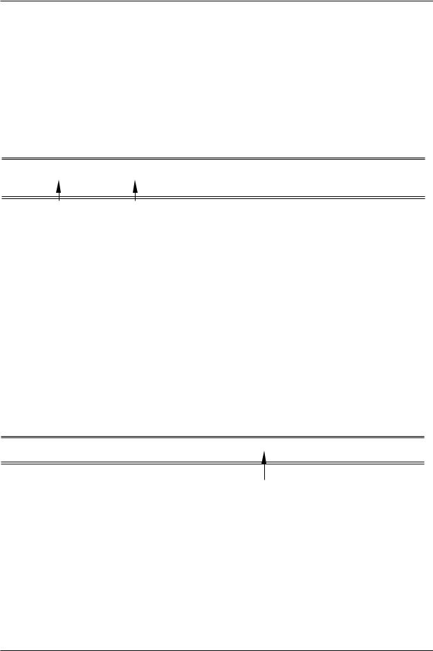
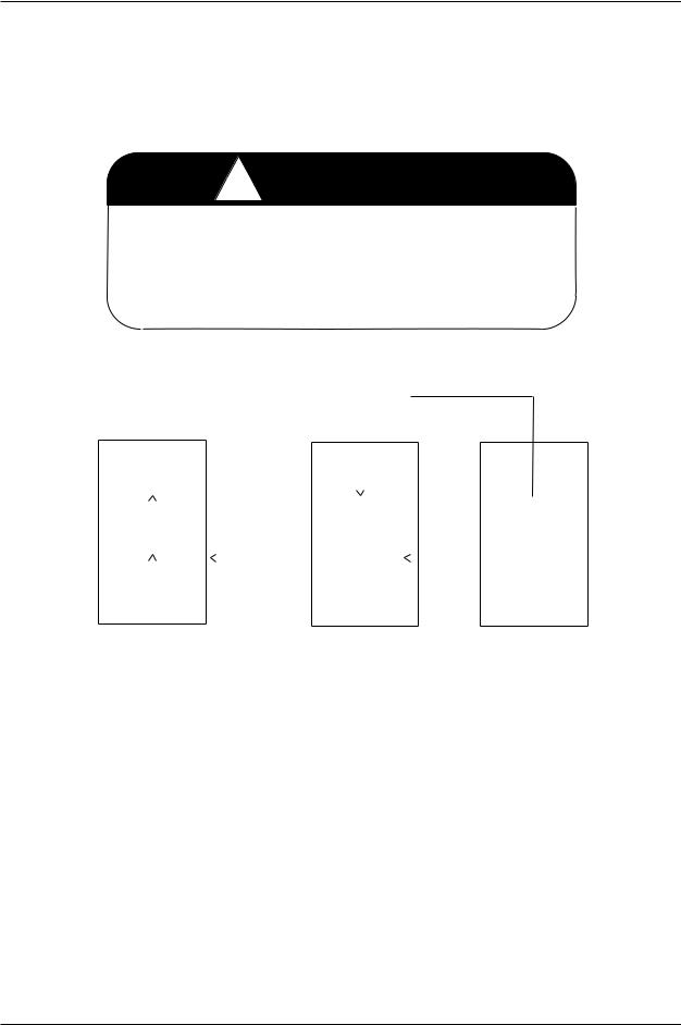
ERROR CODE D1004 [ARM CTRL BOARD] watch dog error of servo control software.
The watch dog circuit on the 1KA board or 1KB board has detected a software problem. This is caused by a defective 1KA main CPU board or 1KB servo CPU board or a problem with the servo software.
1KX (Mother Board) |
Interface |
ELPD |
|
CPU |
|||
|
|
Watch Dog
Error Signal
Servo
1KA (Main CPU Board) Control  Gate Array
CPU
1KB (Servo CPU Board)
Replace the AS or servo software.
Replace the 1KA or 1KB board.
_____________________________________________________________________
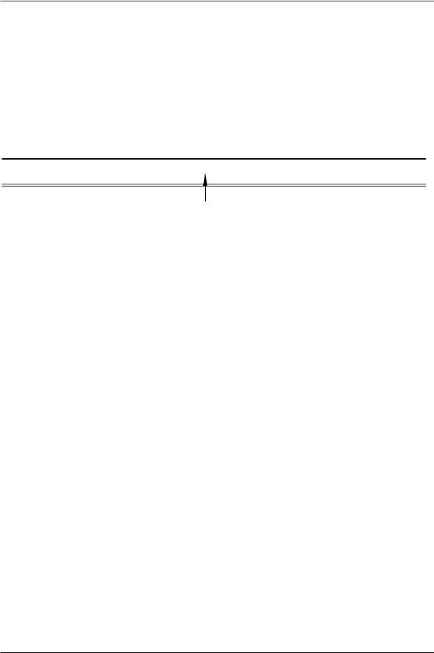
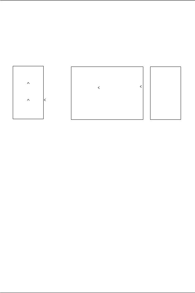
ERROR CODE D1005 |
Servo board command error. (xx) |
Servo software returned an error code, other than a servo system error, to the AS software after receiving an unrecognized command from the 1KA board.
1KX (Mother Board) |
Interface |
ELPD |
|
CPU |
|||
|
|
||
1KA (Main CPU Board) |
Servo |
Gate Array |
|
Control |
|||
|
CPU |
|
|
|
1KB (Servo CPU Board) |
||
Main causes include:
1.Corrupt servo or AS software.
2.Noise malfunction.
3.Defective 1KB servo board or 1KA main CPU board.
4.Versions of servo and AS software incompatible.
Install correct versions of servo and AS software.
Replace the 1KA or 1KB board.
_____________________________________________________________________
1-20 |
August 9, 2005 |
 Kawasak
D SERIES CONTROLLER TROUBLESHOOTING AND COMPONENT REPLACEMENT
TROUBLESHOOTING
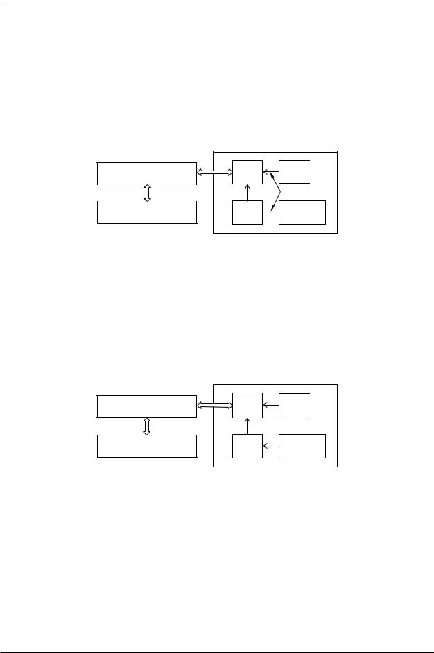
ERROR CODE D1006 |
AMP power unit error. |
General servo system error. This error indicates that a servo system error has occurred. Refer to any other servo system errors which occurred at the same time.
When a servo error signal (SVER) is sent from the 1KB board (servo CPU board) to the 1KP board (power sequence board) motor power is shut down. The error notification is sent to the AS software via the EPLD. The error information from the 1KB board is sent through the command line and the corresponding error code(s) is/are displayed after
D1006.
1KP (Power Sequence Board) |
|
|
|
1KX (Mother Board) |
Interface |
ELPD |
|
CPU |
|||
|
|
||
1KA (Main CPU Board) |
Servo |
Gate Array |
|
Control |
|||
|
CPU |
|
|
|
1KB (Servo CPU Board) |
||
Check the servo error codes that follow this error for additional information. Ensure that the 1KP board and 1KB board are properly seated.
_____________________________________________________________________
August 9, 2005 |
1-21 |
 Kawasak
D SERIES CONTROLLER TROUBLESHOOTING AND COMPONENT REPLACEMENT
TROUBLESHOOTING
ERROR CODE D1007 |
Regenerative time over [XX]. |
This error occurs when current is sent to regenerative resistors for six or more consecutive seconds.
When the robot decelerates, the motors enter the power generation state to absorb the inertia energy from the arm. When the P-N power voltage exceeds the rated value (390 VDC), the current is split from the power block to the regenerative resistor. When the voltage drops to a safe level (365 VDC) the resistor is removed from the circuit.
Motor power
Motor power circuit
|
|
|
|
|
|
|
|
|
|
|
|
|
|
|
|
|
|
|
|
|
|
|
|
|
|
|
|
|
|
|
|
|
|
|
|
|
|
|
|
|
|
|
|
|
|
|
|
|
|
|
|
|
|
|
|
|
|
|
|
|
|
|
|
|
|
|
|
|
|
|
|
|
|
|
|
|
|
Interface |
|
|
|
|
|
|
|
|
|
|
|
|
|
|
|
|
|
|
|
|
|
|
|
|
|
|
|
|
|
|
|
|
|
|
|
|
|
|
|
|
|
|
|
|
|
|
|
|
|
|
|
|
|
|
|
|
|
|
|||||||
|
|
|
|
|
|
|
|
|
|
|
|
|
|
|
|
|
|
|
|
|
|
|
|
|
|
|
P-N power |
|
|
|
|
|
|
|
|
|
|
|
|
|
|
|
|
|
|
|
|
|
|
|
|
|
|||||||||||||||||||
|
|
|
|
|
|
|
|
CPU |
|
|
|
|
|
|
|
|
|
|
|
|
|
|
|
|
|
|
|
|
|
|
|
|
|
|
|
|
|
|
|
|
|
|
|
|
|
|
|
|
|
|
|
|
|
|
|
|
|
||||||||||||||
|
|
|
|
|
|
|
|
|
|
|
|
|
Motor power |
|
|
|
|
voltage |
|
|
|
|
|
|
|
|
|
|
|
|
|
|
|
|
|
|
|
|
|
|
|
|
|
||||||||||||||||||||||||||||
|
|
|
|
|
|
|
|
|
|
|
|
|
|
|
|
|
|
|
|
|
|
|
|
|
|
|
|
|
|
|
|
|
|
|
|
|
Drive circuit |
|
|||||||||||||||||||||||||||||||||
|
|
|
|
|
|
|
|
|
|
|
|
|
|
|
|
|
|
|
|
|
|
(P-N power |
|
|
|
monitoring |
|
|
|
|
|
|
|
|
|
|
|
|
|||||||||||||||||||||||||||||||||
|
|
|
|
|
|
|
|
|
|
|
|
|
|
|
|
|
|
|
|
|
|
|
|
|
|
|
|
|
|
|
|
|
|
|
|
|
1KC: IGBT |
|
|||||||||||||||||||||||||||||||||
|
|
|
|
|
|
|
Servo |
|
|
|
|
|
|
|
|
|
|
voltage) |
|
|
|
|
circuit/ |
|
|
|
|
|
|
|
|
|
|
|
|
|
|||||||||||||||||||||||||||||||||||
|
|
|
|
|
|
|
|
|
|
|
|
|
|
|
|
|
|
|
|
|
|
|
|
|
|
|
|
|
|
|
|
|
1KD: IGBT |
|
|||||||||||||||||||||||||||||||||||||
|
|
|
|
|
|
|
|
|
|
|
|
|
|
|
|
|
|
|
|
|
|
|
|
|
|
|
Regeneration |
|
|
|
|
|
|
|
|
|
|||||||||||||||||||||||||||||||||||
|
|
|
|
|
|
|
|
CPU |
|
|
|
|
|
|
|
|
|
|
|
|
|
|
|
|
|
|
|
|
|
|
|
|
|
|
|
|
|
|
1KL/1KR: FET |
|
|||||||||||||||||||||||||||||||
|
|
|
|
|
|
|
|
|
|
|
|
|
|
|
|
|
|
|
|
|
|
|
|
|
|
|
|
|
controlling |
|
|
|
|
|
|
|
|
|
|
|
|
||||||||||||||||||||||||||||||
|
|
|
|
|
|
|
|
|
|
|
|
|
|
|
|
|
|
|
|
|
|
|
|
|
|
|
|
|
|
|
|
|
|
|
|
|
|
|
|
|
|
|
|
|
|
|
|
|
|
|
|
|
|
|
|
|
|
|
|
|
|
|
|||||||||
|
|
|
|
|
|
|
|
|
|
|
|
|
|
|
|
|
|
|
|
|
|
|
|
|
|
|
|
|
|
|
|
|
|
|
|
|
|
|
circuit |
|
|
|
|
|
|
|
|
|
|
|
|
|
|
|
|
|
|
|
|
|
|
|
|
|
|||||||
|
|
|
|
|
Gate Array |
|
|
|
|
|
|
|
Regenerative |
|
|
|
|
|
|
|
|
|
|
|
|
|
|
|
|
|
|
|
|
|
|
|
Regenerative |
|
|
||||||||||||||||||||||||||||||||
|
|
|
|
|
|
|
|
|
|
|
|
signal |
|
|
|
|
|
|
|
|
|
|
|
|
|
|
|
|
|
|
|
|
|
|
|
|
|
||||||||||||||||||||||||||||||||||
|
|
|
|
|
|
|
|
|
|
|
|
|
|
|
|
|
|
|
|
|
|
|
|
|
|
|
|
|
|
|
|
|
|
|
|
|
|
|
|
|
|
|
|
|
|
|
|
|
resistor |
|
|
||||||||||||||||||||
|
|
|
|
|
|
|
|
|
|
|
|
|
|
|
|
|
|
|
|
|
|
|
|
|
|
|
|
|
|
|
|
|
|
|
|
|
|
|
|
|
|
|
|
|
|
|
|
|
|
|
|
|
|
|
|
|
|
|
|
|
|
||||||||||
|
|
|
|
|
|
|
|
|
|
|
|
|
|
|
|
|
|
|
|
|
|
|
|
|
|
|
|
|
|
|
|
|
|
|
|
|
|
|
|
|
|
|
|
|
|
|
|
|
|
|
|
|
|
|
|
|
|
|
|
|
|
|
|
|
|
|
|
|
|
|
|
|
|
|
|
|
|
|
|
|
|
|
|
|
|
|
|
|
|
|
|
|
|
|
|
|
|
|
|
|
|
|
|
|
|
|
|
|
|
|
|||||||||||||||||||||||||||||||||
|
|
|
|
1KB board |
|
|
|
|
|
|
|
|
|
|
|
|
|
|
|
|
|
|
|
|
|
|
|
|
|
|
|
|
Power block |
|
|||||||||||||||||||||||||||||||||||||
|
|
|
|
|
|
|
|
|
|
|
|
|
|
|
|
|
|
|
|
|
|
|
|
|
|
|
|
|
|
|
|
|
|
|
|
|
|
|
|
|
|
|
|
|
|
|
|
|
|
|
|
|
|
|
|
|
|
|
|
|
|
|
|
|
|
|
|
|
|
|
|
|
|
|
|
|
|
|
|
|
|
|
|
|
|
|
|
|
|
|
|
|
|
|
|
|
|
Controller |
|
|
|
|
|
|
|
|
|
|
|
|
|
|
|
|
|
|
|
|
|
|
|
|
|
|
|
|
|
|
|
|
|
|
|
|
|
||||||||
Main causes include:
1.Abrupt direction changes at high speed.
2.Burned out regenerative resistors in the power block.
3.Defective power block.
4.Defective servo board (1KB board).
5.Loose or disconnected harness between 1KX board (mother board) connector X211 or X212 and the 1KB board (servo CPU board) connector X501 or X502.
6.Defective/incorrect optional second regenerative resistance unit (when used).
Avoid abrupt high speed direction changes. Change accuracy, speed, add points.
Replace defective regenerative resistor.
Install/replace optional second regenerative resistance unit.
Replace defective 1KB board.
Replace defective power block.
Check connections described in item 5 and repair as necessary.
_____________________________________________________________________
1-22 |
August 9, 2005 |
 Kawasak
D SERIES CONTROLLER TROUBLESHOOTING AND COMPONENT REPLACEMENT
TROUBLESHOOTING
ERROR CODE D1008 |
P-N low voltage [XX]. |
The voltage between P-N supplied to the power block is 60 VDC or less at servo on.
!WARNING
Because motor power is not supplied, when low voltage occurs, the arm will fall until the error is detected. As a result, other errors may be generated (abnormal speed, deviation error, etc.).
Primary power |
|
Main |
|
|
MC unit |
|
Motor power |
|||||||
|
|
|
|
disconnect |
|
(1KQ/1NQ board) |
|
|
|
|||||
|
|
|
|
|
|
|
|
|
|
|
|
|
|
|
|
|
|
|
|
|
|
|
|
K3 STATUS |
|
|
|||
|
|
|
|
|
|
|
|
|
|
|
|
|
|
|
|
Interface |
|
|
|
|
|
|
|
|
|
|
|
|
|
|
CPU |
|
|
|
|
|
|
|
|
|
|
|
|
|
|
|
|
|
|
|
|
|
|
|
|
|
|
|
|
|
|
|
|
|
|
|
|
|
|
|
|
|
|
|
|
|
|
|
|
P-N power low |
|
|
|
|
|
|
|
P-N power |
|
|
Servo |
|
|
|
|
|
|
|
|
|||||
|
|
|
|
|
|
|
|
|
|
voltage |
||||
|
|
|
voltage error |
|
EPLD |
|
|
|
|
|||||
|
CPU |
|
|
|
|
|
monitoring |
|||||||
|
|
|
|
|
|
|
|
|
|
|
|
|||
|
|
|
|
|
|
|
|
|
|
|
|
|
|
circuit |
|
|
|
|
|
|
|
|
|
|
|
|
|
||
|
|
|
|
|
|
|
|
|
|
|
|
|
|
|
|
|
|
|
|
|
|
|
|
|
|
|
|
|
|
|
Gate Array |
|
|
|
|
|
|
|
|
|
|
|
|
|
|
|
|
|
|
|
|
|
1KP board |
|
|
||||
1KB board |
|
|
|
|
|
Power block |
||||||||
Main causes include:
1.Motor power circuit connector detached or loose.
2.Three phase (U, V, W) control power circuit breaker set to OFF.
3.Defective 1KB/1KP/1KQ/1NQ boards.
4.Defective power block.
5.Defective MC unit or harness.
Ensure the motor power circuit connector is properly attached.
Ensure control power circuit breaker is set to ON.
Replace the 1KB/1KP/1KQ /1NQ boards.
Replace the power block.
Replace the MC unit or harness.
_____________________________________________________________________
August 9, 2005 |
1-23 |
 Kawasak
D SERIES CONTROLLER TROUBLESHOOTING AND COMPONENT REPLACEMENT
TROUBLESHOOTING
ERROR CODE D1009 |
P-N- high voltage [XX]. |
The voltage between P-N supplied to the power block exceeded 410 VDC.
Primary power |
|
Main |
|
|
|
|
|
|
MC unit |
|
|
|
|
|||
|
|
|
|
disconnect |
|
|
|
|
(1KQ/1NQ board) |
|
|
|
|
|||
|
|
|
|
|
|
|
|
|
|
|
|
|||||
|
|
|
|
|
|
|
|
|
|
|
|
|
|
|
|
|
|
|
|
|
|
|
|
|
|
|
|
Motor power |
|
|
|
|
|
|
|
|
|
|
|
|
|
|
|
|
|
|
|
|
|
|
|
Interface |
|
|
|
|
|
|
|
|
|
|
|
|
|
|
|
|
CPU |
|
|
|
|
|
|
|
|
|
|
|
|
|
|
|
|
|
|
|
|
|
|
|
|
|
|
|
Regenerative |
|
|
Additional |
|
|
|
|
|
|
|
|
|
|
|
|||||||
|
|
|
|
|
P-N power high |
|
P-N power |
|
|
|
resistor |
|
|
regenerative |
|
|
|
Servo |
|
|
|
voltage |
|
|
|
|
|
|
resistor |
|
|||
|
|
|
voltage error |
|
|
|
|
|
|
|
|
|
||||
|
CPU |
|
|
|
monitoring |
|
|
|
Thermal |
|
|
Thermal |
|
|||
|
|
|
|
|
|
|
|
|
|
|
|
|||||
|
|
|
|
|
|
|
|
circuit |
|
|
|
(140° C) |
|
|
|
|
|
|
|
|
|
|
|
|
|
|
|
|
|
(140° C) |
|
||
|
|
|
|
|
|
|
|
|
|
|
||||||
|
|
|
|
|
|
|
|
|
|
|
|
|
|
|
|
|
|
|
|
|
|
|
|
|
|
|
|
|
|
|
|
|
|
|
Gate Array |
|
|
|
|
|
|
|
|
|
|
|
|
|
|
|
|
|
|
|
|
|
|
|
|
Power block |
|
Additional regenerative |
|||||
1KB board |
|
|
|
|
|
|
||||||||||
|
|
|
|
|
|
|
|
|
|
|
|
|
|
resistor (option) |
||
Main causes include:
1.High inertia loads due to excessive tool weight or incorrect program data.
2.Defective regenerative resistance control circuit, overheat failure of regenerative resistance unit, defective voltage monitoring circuit, or defective power block.
3.Defective servo board (1KB board) or harness.
4.Defective additional regenerative resistance unit.
Reteach program steps to eliminate sudden high speed direction changes (dynamic shock).
Replace the regenerative unit.
Replace the 1KB board, power block or harness.
Replace the additional regenerative resistor unit.
_____________________________________________________________________
1-24 |
August 9, 2005 |
 Kawasak
D SERIES CONTROLLER TROUBLESHOOTING AND COMPONENT REPLACEMENT
TROUBLESHOOTING
ERROR CODE D1010 Regenerative resistor over-heat [XX].
The thermal switch for the power block regenerative resistor unit, or the optional regenerative resistor unit reached 140° C (284°F), or the heat sink thermal switch reached 90° C (194°F), or the controller cabinet thermal switch reached 70° C (158° F). The thermal switches are wired in series and the AS software cannot distinguish which thermal switch is activated. For D7X controller, if the heat exchange fan is inoperative
(X207 disconnected) this error is generated.
Primary power |
|
Main |
|
|
|
|
|
|
MC unit |
|
|
|
|
|||
|
|
|
|
disconnect |
|
|
|
|
(1KQ/1NQ board) |
|
|
|
|
|||
|
|
|
|
|
|
|
|
|
|
|
|
|||||
|
|
|
|
|
|
|
|
|
|
|
|
|
|
|
|
|
|
|
|
|
|
|
|
|
|
|
|
Motor power |
|
|
|
|
|
|
|
|
|
|
|
|
|
|
|
|
|
|
|
|
|
|
|
Interface |
|
|
|
|
|
|
|
|
|
|
|
|
|
|
|
|
CPU |
|
|
|
|
|
|
|
|
|
|
|
|
|
|
|
|
|
|
|
|
|
|
|
|
|
|
|
Regenerative |
|
|
Additional |
|
|
|
|
|
|
|
|
|
|
|
|||||||
|
|
|
|
|
P-N power high |
|
P-N power |
|
|
|
resistor |
|
|
regenerative |
|
|
|
Servo |
|
|
|
voltage |
|
|
|
|
|
|
resistor |
|
|||
|
|
|
voltage error |
|
|
|
|
|
|
|
|
|
||||
|
|
|
|
|
|
|
|
|
|
|
|
|||||
|
CPU |
|
|
|
monitoring |
|
|
|
Thermal |
|
|
Thermal |
|
|||
|
|
|
|
|
|
|
|
|
|
|
|
|||||
|
|
|
|
|
|
|
|
circuit |
|
|
|
(140° C) |
|
|
(140° C) |
|
|
|
|
|
|
|
|
|
|
|
|
||||||
|
|
|
|
|
|
|
|
|
|
|
||||||
|
|
|
|
|
|
|
|
|
|
|
|
|
|
|
|
|
|
|
|
|
|
|
|
|
|
|
|
|
|
|
|
|
|
|
Gate Array |
|
|
|
|
|
|
|
|
|
|
|
Additional regenerative |
|||
|
|
|
|
|
|
|
Power block |
|
||||||||
|
|
|
|
|
|
|
|
|
|
|||||||
1KB board |
|
|
|
|
|
|
||||||||||
|
|
|
|
|
|
|
|
|
|
|
|
|
|
resistor (option) |
||
Main causes include:
1.High inertia loads due to excessive tool weight or incorrect program data.
2.Defective cooling fans.
3.Insufficient clearance for air circulation.
4.High ambient controller temperature.
5.Defective power block.
6.Disconnected or defective harness between the 1KC/1KD board and the additional regenerative resistor unit.
7.Defective regenerative resistor unit.
8.Defective additional regenerative resistor unit.
9.Defective 1KB board.
10.Disconnected or defective harness between X211 or X212 on the 1KX/1NX board and X501 or X502 on the power block.
August 9, 2005 |
1-25 |

 Kawasak
D SERIES CONTROLLER TROUBLESHOOTING AND COMPONENT REPLACEMENT
TROUBLESHOOTING
Reteach program steps to eliminate sudden high speed direction changes (dynamic shock).
Ensure cooling fans are in proper working condition.
Reduce controller ambient temperature.
Replace defective thermal switch(es).
Repair or replace disconnected or defective harness(es).
Replace the regenerative unit.
Replace the 1KB board, power block or harness.
Replace the additional regenerative resistor unit.
Connect or repair D7X power supply connection for heat exchange fan (X207).
_____________________________________________________________________
ERROR CODE D1011 AS or servo software is not compatible with the robot model.
This error occurs when the servo software does not match the robot specifications.
Load the correct AS and servo software.
_____________________________________________________________________
ERROR CODE D1012 |
Servo type mismatch. Check the settings. |
Servo type set for the robot and servo software do not match.
Change the robot servo type setting.
Install servo software that matches the robot setting.
_____________________________________________________________________
1-26 |
August 9, 2005 |
 Kawasak
D SERIES CONTROLLER TROUBLESHOOTING AND COMPONENT REPLACEMENT
TROUBLESHOOTING
ERROR CODE D1013 P-N capacitor is not discharged.
This error occurs when motor power is OFF for a period of time and the P-N power voltage does not decrease to 60 VDC or less.
Primary power |
|
Main |
|
|
MC unit |
|
Motor power |
|||||||
|
|
|
|
disconnect |
|
(1KQ/1NQ board) |
|
|
|
|||||
|
|
|
|
|
|
|
|
|
|
|
|
|
|
|
|
|
|
|
|
|
|
|
|
K3 STATUS |
|
|
|||
|
|
|
|
|
|
|
|
|
|
|
|
|
|
|
|
Interface |
|
|
|
|
|
|
|
|
|
|
|
|
|
|
CPU |
|
|
|
|
|
|
|
|
|
|
|
|
|
|
|
|
|
|
|
|
|
|
|
|
|
|
|
|
|
|
|
|
|
|
|
|
|
|
|
|
|
|
|
|
|
|
|
|
P-N capacitor |
|
|
|
|
|
|
|
P-N power |
|
|
Servo |
|
|
|
|
|
|
|
|
|||||
|
|
|
|
|
|
|
|
|
|
voltage |
||||
|
|
|
discharge error |
|
EPLD |
|
|
|
|
|||||
|
CPU |
|
|
|
|
|
monitoring |
|||||||
|
|
|
|
|
|
|
|
|
|
|
|
|||
|
|
|
|
|
|
|
|
|
|
|
|
|
|
circuit |
|
|
|
|
|
|
|
|
|
|
|
|
|
||
|
|
|
|
|
|
|
|
|
|
|
|
|
|
|
|
|
|
|
|
|
|
|
|
|
|
|
|
|
|
|
Gate Array |
|
|
|
|
|
|
|
|
|
|
|
|
|
|
|
|
|
|
|
|
|
1KP board |
|
|
||||
1KB board |
|
|
|
|
|
Power block |
||||||||
Main causes include:
1.Defective 1KB/1KP/1KQ/1NQ boards.
2.Defective power block.
3.Defective MC unit or harness between the MC unit and the power block.
Replace the 1KB/1KP/1KQ/1NQ boards.
Replace the power block.
Replace the MC unit or harness between the MC unit and the power block.
_____________________________________________________________________
ERROR CODE D1014 |
Servo system error. (Code=XX) |
An unrecognized error occurred in the 1KB board.
Contact KRI customer service (include operating conditions/settings at the time the error occurred).
_____________________________________________________________________
ERROR CODE D1015 The servo data file does not exist.
This error occurs when the servo data file is not found.
Contact KRI customer service (include operating conditions/settings at the time the error occurred).
_____________________________________________________________________
August 9, 2005 |
1-27 |
 Loading...