


User manual
UFX 314 data bus de-multiplexer
(BN 20610071)

Contents
|
|
Page |
|
General |
3 |
1. |
Features |
3 |
2. |
Mechanical layout |
4 |
2.1 |
Rear view |
4 |
2.2 |
Front view |
4 |
2.3 |
Status LEDs |
4 |
3.Installation
3.1 |
Installation |
5 |
3.2 |
UFO®compact controller |
7 |
3.3 |
Network configuration |
7 |
3.4 |
USB installation |
8 |
|
3.4.1 Microsoft Windows |
8 |
|
3.4.2 Linux |
11 |
4. |
Software Update |
11 |
5.Web interface
5.1 |
The main page |
12 |
|
5.1.1 The device group box |
12 |
|
5.1.2 The system group box |
12 |
5.2 |
Log page |
12 |
5.3 |
Status page |
13 |
5.4 |
Update page |
13 |
6.Modem access
6.1 |
Setting up in Microsoft Windows |
13 |
6.2 |
Setting up in Linux |
19 |
7. |
Open source |
22 |
2
General
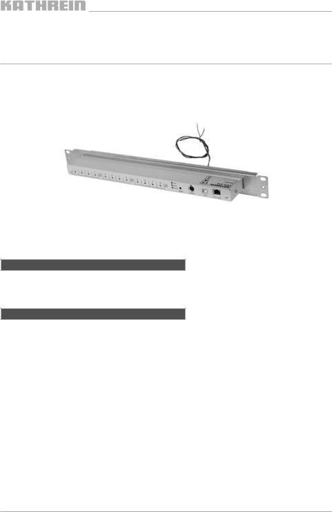
The UFX 314 data bus de-multiplexer (BN 20610071) is used for the central control of all channel units installed in a UFG 412 base unit. Each channel unit is connected using a separate cable. Several demultiplexers can be connected to a system over a network.
1. Features
Facilitates the use of the USW 30 control software
Required on the use of certain functions for some channel units, e. g. for NIT generation Can be used to update older UFO®compact systems
Control of individual channel units using UFO®compact controller (from software version 9.20) or PC with control software USW 30 (version 3.2)
Feature for remote maintenance over LAN as well as analogue, ISDN or GSM modem Up to eight UFX 314 can be configured over LAN to form a group
Up to 256 groups can be controlled independently of each other in a LAN segment
3

2. Mechanical layout
The points are described in the plan view from left to right.
2.1 Rear view
Redundant Power System |
Expansion connection for monitoring a redundant power supply, currently has |
|
no function |
Modem |
USB port for connecting a modem (see section 6) or a USB stick |
Power |
Power connection 12.5 V/approx. 200 mA (without controller or USB device), |
|
max. 900 mA |
12 x Mini-DIN sockets |
For the connection of up to 12 UFO®compact channel units |
2.2 Front view
12 x port LEDs |
These LEDs are used to indicate the channel unit to which a control unit is |
|
currently connected |
3 status LEDs |
Error (red), Event (yellow), Power (green) |
Reset button |
For manually re-starting the device |
Mini-DIN socket |
For the connection of a handheld controller |
USB device port |
For the connection to a PC, with USW 30 |
RJ45 socket |
10/100 Mbit Ethernet, for connecting several UFX 314 and a control PC |
2.3 status LEDs
The Power LED illuminates as soon as the UFX 314 is supplied with power. The status is indicated using the Error LED and Event LED. The Event LED illuminates during the start phase and extinguishes as soon as the UFX 314 is ready. The Error LED and Event LED illuminate continuously during a software update. At the end of the update, the Event LED extinguishes. When the device is then re-started, the Error LED also extinguishes, and the Event LED illuminates at the start.
In normal operation, the Error LED and Event LED signal the presence of messages. An illuminated Event LED signifies that information has been written to the log. If the Event LED is flashing, a warning has been generated, it should still be possible to continue to operate the UFX 314. The flashing Error LED signifies that an error
has occurred and the correct operation of the UFX 314 is no longer assured. If the Error and Event LED flash alternately, a serious error has occurred making normal operation more or less impossible.
4
3. Installation
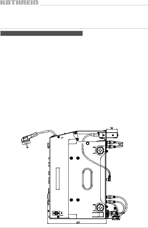
3.1 Installation
The demultiplexer is installed in the 1 HU fan unit that is mounted above the base unit.
For this purpose the following steps are required:
Fit the UFX 314 into the 19” front panel (1 HU) supplied Remove the pre-assembled blanking plate
Connect straight connectors on connecting cables to the demultiplexer (mini-DIN sockets 1 ... 12) The angled version is to be connected to the modules
If a modem is being used, an RS 232 adapter must be connected (special accessory, not included with the UFX 314). The modem operates independently of the demultiplexer to which it is connected
Now push the demultiplexer into the 1-HU front unit from the front and screw into place
Then connect the power supply unit power cable to the blue terminals (black = ground, brown = 12 V 5)
The channel unit → UFX 314 connecting cables should always be laid to the right along the related channel unit (exception: channel unit on the extreme right)
Where the following text refers to a switch, a hub can also be used as an alternative. It is also possible to connect the control PC to the switch. If only two UFX 314 are to be connected together, a crossed Ethernet cable can be used - however in this case a control PC can then only be connected using USB.
5

6
Kaananel z ug 1 |
|
|
ChannelKa na zunitug1212 |
|
Ch |
unit 1 |
483 |
|
|
|
|
|
|
|
|
|
|
|
|
( )=1HE
44
( )=8HE
355
Channel unit 1 |
ChaKa nanelzunitug1212 |
Ka na l z ug 1 |
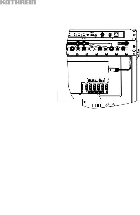
Connect the power cable for the UFX 314 to the screw terminals in the power supply for the base unit
3.2 UFO®compact controller
The UFO®compact controller can be connected to any of the demultiplexers. However, it is to be noted that the controller only operates with the demultiplexers that belong to the same group to which it is connected. The usage of an older UFO®compact controller prior to software version 9.20 is in principle possible, however there may be connection problems with the channel units.
Only one control system can be active per group, this means that you can only access the group using one UFO®compact controller or with one USW 30. As the groups are independent of each other, several groups in a network can be controlled at the same time.
3.3 Network configuration
Connect several UFX 314 using a network. If you want to integrate the devices into an existing network, you should consult the responsible network administrator to prevent problems from the start. Firewall and antivirus applications may adversely affect the function.
The network configuration for the UFX 314 can only be undertaken using the controller software USW 30 and is described in section 7 of the manual provided with the software.
In the delivery status, every demultiplexer is set to “Zeroconf”. Microsoft Windows also uses this method if a fixed IP address has not been defined and a DHCP server is not available.
The related standard was published by the IETF under “RFC 3927” 1). The devices in the network select a spare IP address from the range 169.254.1.0 to 169.254.255.0 and use the network mask 255.255.0.0.
The USW 30 connects with a demultiplexer in the group using TCP port 9312 and can then communicate with all other multiplexers in this group over this connection. It does not matter to which device in a group the USW 30 connects. Between the UFX 314 a TCP connection on port 9313 is used.
To establish a connection via a router, the router must forward port 9312 to a UFX 314.
The UFX 314 does not have any access protection for Ethernet or USB access, for this reason instead of simple port forwarding, the usage of a virtual private network (VPN) should be considered. You will find information on VPN in the related specialist literature and on the Internet.
The “Multicast DNS” 2) and “DNS Service Discovery” 3) protocols used for the network search use Multicast packets on UDP port 5353. The network is searched by each UFX 314 to find other devices in its group.
1) http://files.zeroconf.org/rfc3927.txt |
2) http://www.multicastdns.org/index.html |
3) http://www.dns-sd.org/index.html |
7 |
3.4 USB installation
3.4.1 Microsoft Windows
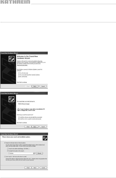
You will find the driver for the connection of a PC using USB on the USW 30 control software CD (not included). To install the driver, you will need administrator permissions on the PC. The installation is described based on the English version of Windows XP.
If the UFX 314 indicates an error after connecting/changing connections, or if it is not correctly detected by Windows, disconnect it from the PC and restart it using the Reset button. Before reconnecting to the PC, wait until the demultiplexer has started completely (see 2.3 Status LEDs).
After the UFX 314 is connected, a wizard for installing new hardware appears.
Choose “No, not this time” and click “Next” to open the next page in the wizard.
Select “Install from a list or specific location”.
Select “Search for the best driver in these locations” and “Include this location in the search:”.
By clicking “Browse” you can open a dialog box where you can open the folder "UFX314\drivers" on the USW 30 CD.
In the event of an update to the USW 30, the drivers can be found in the software installation folder.
8
 Loading...