


Service Handbook
Waterclean 600 CD,
LP/MP, PI
1.024-...
5.905-521
08.2004

FOREWORD |
WTC 600 LP / MP |
Foreword
Good servicing and maintenance requires comprehensive, practical training and clearly organised documents.
This is why we offer all servicing engineers regular basic training and further qualification courses for the whole product range.
In addition, we compile service manuals for the main units which can be used as instructions to start with and as a reference work later on.
In addition, we issue regular Service Information about on-going developments of our products.
The texts and pictures can only be copied and duplicated or passed on to third parties after obtaining explicit permission from:
ALFRED KÄRCHER GmbH & Co.
CUSTOMER SERVICE TRAINING
P. O. Box 160
D-71349 Winnenden
www.kaercher.com
2 |
Service Handbook 08.2004 |

WTC 600 LP / MP |
CONTENTS |
Contents |
|
1 General.......................................................................................... |
7 - 10 |
|
1.1 |
Introduction ........................................................................................................... |
7 |
1.2 |
Marking of Instructions ........................................................................................ |
7 |
1.3 |
Intended Use .......................................................................................................... |
7 |
1.4 |
Safety Instructions ................................................................................................ |
8 |
1.4.1 |
Quality of the Untreated Water ................................................................................. |
8 |
1.4.2 |
Chlorination of Drinking Water .................................................................................. |
8 |
1.4.3 |
Disposal of Chemicals ............................................................................................. |
8 |
1.4.4 |
Handling Electricity / Protection Class ..................................................................... |
9 |
1.5 |
General installation notes .................................................................................. |
10 |
1.6 |
Units and Designations ....................................................................................... |
11 |
2 Description ................................................................................ |
11 - 20 |
|
2.1 |
Overview .............................................................................................................. |
11 |
2.2 |
Flow Diagram ...................................................................................................... |
13 |
2.3 |
Description of the System .................................................................................. |
14 |
2.3.1 |
Modular Design ...................................................................................................... |
14 |
2.3.1.1 |
Pre-chlorination Module ......................................................................................... |
14 |
2.3.1.2 |
Flocculation Module............................................................................................... |
14 |
2.3.1.3 |
Mediafilterand Activated Carbon Filter ................................................................ |
15 |
2.3.1.4 RO System, Pump and Fine Filter ........................................................................ |
15 |
|
2.3.1.5 |
Control Panel and Display ..................................................................................... |
15 |
2.3.1.6 |
Anti Scalant and Post Chlorination ........................................................................ |
15 |
2.3.1.7 |
Pressure-increase Pump ...................................................................................... |
16 |
2.3.2 |
Safety Installations ................................................................................................. |
16 |
2.3.3 |
Operating Modes .................................................................................................... |
17 |
2.3.3.1 |
Automatic Operation (Standard Operating Mode) ................................................. |
17 |
2.3.3.2 |
Manual Operation .................................................................................................. |
17 |
2.4 |
Technical Data WTC 600 LP/MP ......................................................................... |
18 |
2.5 |
Consumption Materials ...................................................................................... |
20 |
2.5.1 |
Chemicals for Metering Container .......................................................................... |
20 |
2.5.2 |
Cleaning Chemicals ............................................................................................... |
20 |
2.5.3 |
Filter ....................................................................................................................... |
20 |
3 Operation of the System .......................................................... |
21 - 43 |
|
3.1 |
Assembly and Starting Operation ..................................................................... |
21 |
3.2 |
Mixing Chlorine, Flocculation Agent and Antiscalant ..................................... |
22 |
3.2.1 |
Initial Starting of Operation ..................................................................................... |
22 |
3.2.2 |
Pre-chlorination ...................................................................................................... |
22 |
3.2.3 |
Antiscalant.............................................................................................................. |
24 |
3.2.4 |
Metering Amounts and Mixing of the Post Chlorination .......................................... |
25 |
3.2.5 |
Flocculation Agent .................................................................................................. |
25 |
3.2.5.1 |
Mixing of the flocking test solution .......................................................................... |
25 |
Service Handbook 08.2004 |
3 |

CONTENTS |
|
WTC 600 LP / MP |
Contents |
|
|
3.2.5.2 |
Perform flocking test............................................................................................... |
26 |
3.2.5.3 |
Evaluate flocking test ............................................................................................. |
26 |
3.3 |
Connecting the Equipment ................................................................................ |
27 |
3.3.1 |
Connections, Valves and Indicators ....................................................................... |
27 |
3.3.1.1 |
Pressure-increase Module .................................................................................... |
28 |
3.3.1.2 |
RO Module with Preliminary Filters ....................................................................... |
28 |
3.3.2 |
Electrical Connections ........................................................................................... |
29 |
3.3.2.1 |
Pressure-increase Pump ...................................................................................... |
29 |
3.3.2.2 |
Preliminary Filter ................................................................................................... |
29 |
3.3.2.3 |
Metering Station .................................................................................................... |
29 |
3.3.2.4 |
Float Switch ........................................................................................................... |
31 |
3.3.2.5 |
Reverse Osmosis System .................................................................................... |
31 |
3.4 |
Starting Operation ............................................................................................... |
31 |
3.4.1 |
Metering Station ..................................................................................................... |
31 |
3.4.2 |
Media filter and activated carbon filter .................................................................... |
32 |
3.4.2.1 |
Initial Filling ............................................................................................................ |
32 |
3.4.2.2 |
Starting Operation ................................................................................................. |
32 |
3.4.2.3 |
Backwashing / Regeneration ................................................................................ |
32 |
3.4.2.4 |
Programming ......................................................................................................... |
33 |
3.4.3 |
Starting Operation of the RO System .................................................................... |
35 |
3.4.3.1 |
Operating Levels and Passwords ......................................................................... |
35 |
3.4.3.2 |
Menu Selection ...................................................................................................... |
35 |
3.4.3.3 |
Selection of an Option ........................................................................................... |
35 |
3.4.3.4 |
Selecting Several Arguments at the Same ............................................................ |
36 |
3.4.3.5 |
Adjusting Operating Parameters and Balancing Values ......................................... |
36 |
3.4.3.6 |
Acknowledging Data Inputs .................................................................................. |
36 |
3.4.3.7 |
Operational Interruptions ....................................................................................... |
36 |
3.4.3.8 |
Initial startup ........................................................................................................... |
38 |
3.4.4 |
Normal Operation ................................................................................................... |
40 |
3.4.4.1 |
Operating Messages for Normal Operation .......................................................... |
41 |
3.4.5 |
Putting Out of Operation ......................................................................................... |
42 |
3.4.6 |
Disinfection............................................................................................................. |
43 |
4 Maintenance .............................................................................. |
44 - 62 |
|
4.1 |
Fine Filter ............................................................................................................. |
44 |
4.2 |
Metering Station WTC 600 CD ............................................................................ |
44 |
4.3 |
Reverse Osmosis Module (RO Module) ............................................................ |
45 |
4.3.1 |
RO Filter Replacement ........................................................................................... |
45 |
4.4 |
Cleaning in Case of Malfunction ........................................................................ |
46 |
4.4.1 |
Design of the Flushing and Disinfection Equipment ............................................... |
47 |
4.4.2 |
Disinfection............................................................................................................. |
49 |
4.4.3 |
Acidic and Alkaline Cleaning .................................................................................. |
50 |
4.4.3.1 |
Cleaning Solution for Acidic Cleaning ................................................................... |
51 |
4 |
Service Handbook 08.2004 |

WTC 600 LP / MP |
CONTENTS |
||
Contents |
|
|
|
4.4.3.2 |
Cleaning Solution for Alkaline Cleaning ................................................................. |
|
51 |
4.4.4 |
Conserving ............................................................................................................. |
|
51 |
4.4.4.1 |
Draining and rinse the metering stations ................................................................ |
|
51 |
4.4.4.2 |
Conserve RO systems .......................................................................................... |
|
51 |
4.4.4.3 |
Draining the pre-filter .............................................................................................. |
|
53 |
4.4.5 |
Removing the Preservation After Longer Operational Interruptions ....................... |
|
53 |
4.4.6 |
Rinsing the pre-filter ............................................................................................... |
|
54 |
4.4.7 |
Replacing the activated carbon or filter sand ......................................................... |
|
55 |
4.5 |
Malfunction, Cause and Corrective Action ....................................................... |
|
57 |
4.5.1 |
Metering Station LED and Indicator LEDs at the Switch Cabinet ........................... |
|
57 |
4.5.2 |
Malfunction Indication at the Operating Panel ........................................................ |
|
58 |
4.5.3 |
Malfunctions of the RO Control and Metering Pump .............................................. |
|
59 |
4.5.4 Malfunctions – Sand and Activated Carbon Filter, Fine Filter and Flocculation ...... |
60 |
||
4.6 |
Maintenance Plan ................................................................................................ |
|
61 |
4.6.1 |
Maintenance During Operation ............................................................................... |
|
61 |
4.6.2 |
Maintenance Plan Service ..................................................................................... |
|
62 |
Appendix ................................................................................... |
63 - 84 |
||
|
RO control manufacture settings .......................................................................... |
|
63 |
|
RO control program structure ............................................................................... |
|
65 |
|
RO 1000: User manual ........................................................................................... |
|
67 |
|
Operating Record for the WTC 600 LP/MP ........................................................... |
|
84 |
List of key words ............................................................................. |
86 - 88 |
||
Service Handbook 08.2004 |
5 |

WTC 600 LP / MP
6 |
Service Handbook 08.2004 |

WTC 600 LP / MP |
GENERAL |
1 General
1.1Introduction
This service manual contains basic instructions and information which are to be observed upon set-up, operation and maintenance.
Therefore, it is imperative that the service manual is read by the installer as well as by the responsible specialist staff prior to installation and starting of operation. Please observe not only the general safety instructions listed in the section “Safety Instructions”, but also the special safety instructions included in the other sections.
1.2Marking of Instructions
The safety instructions contained in these operating instructions, which in case of non-observance can cause dangerous situations for persons, are specially marked with the general symbol for dange.
The safety instructions contained in these operating instructions, which in case of non-observance can cause poisoning, cauterizing, etc. for persons, are specially marked with the death’s-head symbol.
CAUTION Following this symbol are recommendations or tips which make working easier and provide for secure operation.
NOTE Following this symbol are recommendations or tips which make working easier and provide for secure operation.
Instructions that are attached directly to the equipment must be observed under all means and kept in completely readable condition.
1.3Intended Use
The equipment is intended for the conditioning of untreated water into drinking water.
The retention degree of harmful chemical substances and biological pathogens or contaminants is very high.
The quality of the produced drinking water ultimately depends on the contamination degree and salt content of the untreated water.
-Prior to the initial starting of operation, we recommend carrying out an analysis of the untreated water.
-Continuous drinking-water quality can be ensured only when the equipment is controlled regularly.
-The respective national or international drinking water regulations are to be observed.
Under consideration of these rules of conduct, water produced from this system can quite safely be classified as drinking water.
Service Handbook 08.2004 |
7 |

GENERAL |
WTC 600 LP / MP |
1.4Safety Instructionse
1.4.1Quality of the Untreated Water
Sufficient quality of the untreated water must be ensured!
Faultless drinking water is achieved only when all filters of the equipment are maintained regularly.
1.4.2Chlorination of Drinking Water
When applying post chlorination, the limit values set by national laws must be maintained. The chemicals used have a caustic and fire-promoting effect.
Dangers:
-Danger of fire in case of contact with combustible materials.
-Toxic gas develops when coming in contact with acids.
-Heat or direct sunlight decomposes the chemical: Chlorine and oxygen are released.
-Caustic effects to the eyes, skin and respiratory system result.
Safety Instructions:
-Wear acid-resistant protective equipment (goggles, gloves) and when dust is produced, breathing mask protection with a filter.
-Keep an eye wash bottle (small) readily available.
-Provide for adequate room ventilation and a washing facility.
-Store the chemicals in a cool, dry place, not below 5 °C.
-Store chemicals in a location out of the reach of children.
In Case of Accidents:
-In case of contact with the eyes, rinse immediately and thoroughly with fresh water and consult a doctor.
-Use water to extinguish; avoid impact and friction.
-If solutions are spilt, flush the area with a sufficient amount of fresh water.
1.4.3Disposal of Chemicals
It is generally recommended to admit resulting disinfection solutions, preservation solutions, etc. into a neutralizing system.
If this should not be possible, the disinfection solution, after clarification with the relevant authority (mayor’s office, district administration office, etc.) is to be neutralized and can afterwards be led into the public sewer system.
8 |
Service Handbook 08.2004 |

WTC 600 LP / MP |
GENERAL |
1.4.4Handling Electricity / Protection Class
Be aware of dangerous electrical voltage!
For work on components/assemblies which are marked with this symbol, protective measures are to be taken:
-Switch off the power
-Secure against restarting
-Check and assess that no voltage is given.
The electrical connection of the equipment may be carried out only by a qualified electrician.
The power supply cable must be fitted with a protective conductor (protection class I).
1.5General installation notes
-Only use food safe components and resources on the drinking water side
-Pay special attention to hygienic cleanliness when installing drinking water pipes.
1.6Units and Designations
Unit |
|
Designation |
|
|
|
bar |
|
bar (pressure) |
|
|
|
di/da |
|
Diameter, inside / diameter, outside |
|
|
|
g/h |
|
Gram per hour |
|
|
|
Hz |
|
Hz (frequency) |
|
|
|
l |
|
Liter |
|
|
|
l/h |
|
Liter per hou |
|
|
|
mg/h |
|
Milligram per hour |
|
|
|
mg/l |
|
Milligram per lite |
|
|
|
ml |
|
Milliliter |
V AC |
|
Volt (AC) |
|
|
|
W |
|
Watt (power) |
|
|
|
°dH |
|
Degree of hardness (water hardness) |
|
|
|
µS/cm |
|
Microsiemens per cm (spec. conductance value |
|
|
|
ETL |
|
Spare parts list |
|
|
|
LW |
|
Conductance value |
|
|
|
SLP |
|
Circuit Diagram |
|
|
|
Table 1 Units and their meaning |
||
NOTE |
1000 milliliter = 1 liter; 1000 mg = 1 |
|
Service Handbook 08.2004 |
9 |
DESCRIPTION |
WTC 600 LP / MP |
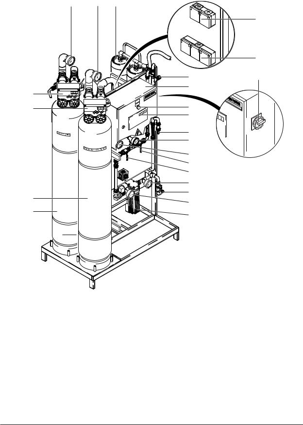
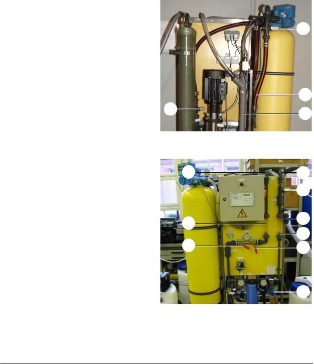
2 Description
2.1Overview
1.2 |
2.1 |
4.12, 4.13 |
f
|
|
g |
|
4.23 |
e |
|
c |
|
b |
|
|
a |
d |
|
4.24 |
|
|
|
|
|
|
4.21 |
|
|
4.14 |
|
|
4.11 |
|
|
4.15 |
|
|
4.17 |
|
|
4.4 |
|
2.2 |
4.3 |
|
4.7 |
|
|
|
|
|
1.3 |
4.5, 4.6 |
|
|
|
Figure 1 Overview of components
10 |
Service Handbook 08.2004 |
WTC 600 LP / MP |
DESCRIPTION |
Legend for figure 1 and figure 2:
1.1 |
Pre-chlorination metering point |
4.11 |
Manometer, pump pressure |
|
1.2 |
Manometer - media filter inlet pressure |
4.12 |
Membrane pressure pipe |
|
1.3 |
Media filter |
4.13 |
Membrane |
|
1.4 |
Differential pressure switch |
4.14 |
Manometer - concentrate pressure |
|
1.5 |
Concussion restrictor |
4.15 |
Concentrate control valve |
|
1.6 |
Flocculation metering point |
4.16 |
Concentrate flowmeter |
|
2.1 |
Manometer - activated carbon filter |
4.17 |
Pressure control valve |
|
|
inlet pressure |
4.18 |
High-pressure pump |
|
2.2 |
Activated carbon filter |
|||
4.19 |
Conductivity and temperature |
|||
4.1 |
Antiscalant metering point |
|||
|
measuring cell - drinking water |
|||
4.2 |
Non-return valve |
4.20 |
Drinking water flowmeter |
|
4.3 |
Untreated water sampling tap |
4.21 |
Drinking water sampling tap |
|
4.4 |
Manometer - fine filter input pressure |
4.22 |
Non-return valve |
|
4.5 |
Fine filter housing |
4.23 |
Post chlorination metering point |
|
4.6 |
Fine filter candle |
4.24 |
Reverse osmosis control |
|
4.7 |
Manometer - fine filter output pressure |
6.1 |
Pre-chlorination metering |
|
4.8 |
Input solenoid valve |
6.2 |
Antiscalant metering |
|
4.9 |
Manostat |
6.3 |
Post chlorination metering |
|
4.10 |
High-pressure pump |
6.4 |
Flocculation metering |
Items 1.1 to 6.4 are attached to the components as reference numbers.
aMedia filter control
bControl, activated carbon filter
cControl cabinet
dManual / automatic rotary switch
eMaster switch
fMedia and activated charcoal plug sockets
gPower outlets (3x) for metering stations
Service Handbook 08.2004 |
11 |

DESCRIPTION |
WTC 600 LP / MP |
2.2Flow Diagram
Figure 2 Flow diagram of the complete reverse osmosis system (RO system)
12 |
Service Handbook 08.2004 |
WTC 600 LP / MP |
DESCRIPTION |
2.3Description of the System
2.3.1Modular Design
The installation is a drinking water conditioning system. Its core application is the emineralization of brackish water with a salt content up to 2000 ppm (WTC 600 LP), respectively up to 5000 ppm (WTC 600 MP).
The design of the system is modular, and can be adapted accordingly to the local conditions depending on the application conditions as well as the composition of the untreated water:
-Media filter and flocculation – module 1
-Activated carbon filter – module 2
-Reverse osmosis system – module 4
-Pressure-increase pump – module 5
-Metering stations
The RO system is designed for stationary use.
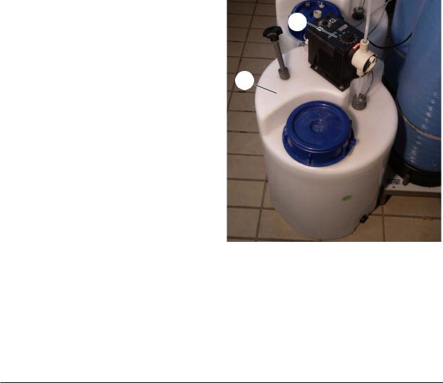
2.3.1.1Pre-chlorination Module
The WTC 600 CD metering station, consisting
of metering container (3/1) and pump (3/2), is
2
connected to the sand filter module for prechlorination if required.
1
Figure 3 WTC 600 CD
2.3.1.2Flocculation Module
The WTC 600 CD metering station (see figure 3) with injection adapter is connected to the sand filter module for pre-flocculation if required.
The exact requirement of flocculation agent is to be determined when starting operation (see Section 3.2.5).
Service Handbook 08.2004 |
13 |
DESCRIPTION |
WTC 600 LP / MP |
2.3.1.3Mediafilterand Activated Carbon Filter
The pre-filter units of the RO system consist of the media filter and the activated carbon filter.
The filter fillings consist of support pebbles and filter sand according to DIN 19623, as well as activated carbon.
The filters are each controlled by means of a central control valve with microprocessor control and located at the top of the filter.
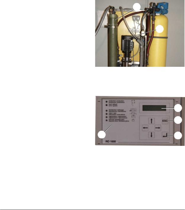
2.3.1.4RO System, Pump and Fine Filter
The fine filter is located on the front side of the
equipment. It is connected directly in front of 1 the RO system.
The RO pump (4/2) pumps the pre-filtered
water through two RO filters (4/1) which are 2 connected in series.
2.3.1.5Control Panel and Display
The control panel is used for data input in the control and as LED indicator for the operating modes and malfunction indications (5/1).
Parameters are entered with the arrow pushbuttons. Data input is acknowledged with the ENTER pushbutton (5/4) and cancelled with the ESC pushbutton (5/3).
Programming conditions, etc., are indicated in the display (5/2).
Figure 4 RO pump
2
3
1 |
4 |
Figure 5 Control panel and display
2.3.1.6Anti Scalant and Post Chlorination
For hardness stabilization of the untreated water and post chlorination of the drinking water a WTC 600 CD metering station is connected to the RO module in the same manner as for prechlorination.
14 |
Service Handbook 08.2004 |

WTC 600 LP / MP |
DESCRIPTION |
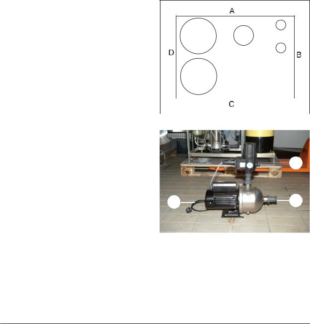
2.3.1.7Pressure-increase Pump
If required, the WTC 600 PI pressure-increase pump (6/1) is connected between untreated water supply and RO system. It is used for pressure increase of the untreated water.
NOTE A pressure-increase pump should be used for a water pressure (flow pressure) 2 bar.
CAUTION Observe mechanical protection as well as protection of the connection cable against water!
1
Figure 6 WTC 600 PI
2.3.2Safety Installations
Emergency Stop
The emergency stop switch (7/4) (main switch) is located on the side of the switch box.
RC Protective Switch
RC protective switch (external): i 30 mA
Circuit Breaker
Automatic circuit breaker (7/3) 10 A for power limitation of the power outlets, etc
Motor Protection Switch
The motor protection switch (7/2) is factory-set depending on the power consumption of the RO pump (compare circuit diagram (7/1)) and must be checked:
WTC 600 |
Nominal output |
Actual power |
Motor protection |
|
RO pump |
consumption |
switch setting |
|
|
|
|
LP 400 V |
2.2 kW |
1.5 kW |
4 A |
|
|
|
|
MP 400 V |
2.2 kW |
2.2 kW |
5.1 A |
|
|
|
|
|
|
|
|
LP 230V |
2.2 kW |
1.5 kW |
10 A |
|
|
|
|
MP 230 V |
2.2 kW |
2.2 kW |
14 A |
|
|
|
|
Table 2 Setting of motor protection switch
Service Handbook 08.2004 |
15 |

DESCRIPTION |
|
|
WTC 600 LP / MP |
|
Microfuses |
|
|
|
|
Two microfuses (7/6) for protection of the |
|
3 |
|
|
control electronics (7/5) are located on the |
2 |
4 |
5 |
|
control board for the electronics: |
1 |
|
|
|
|
|
|
||
|
|
|
|
|
- 5x20 6,3 A time-delay |
|
|
|
|
- 5x20 0,1 A time-delay. |
|
|
|
6 |
|
|
|
|
|
Figure 7 Switch cabinet and control electronic
2.3.3Operating Modes
2.3.3.1Automatic Operation (Standard Operating Mode)
After switching on the main switch, the system is fully automatic controlled through the electronic control system and the float switch in the drinking water tank. The mode selector switch is in the “Auto” position.
The control system usually operates in the normal plane in the operating mode operation.
With the exception of an error acknowledgement (only in case of pre-selection Vwacknowledgement by actuating the ESC key button), no further operating by the operator is possible; this is to protect the control system against unintended / unauthorized manipulations.
NOTE By entering the respective password, the user level or the technician level for input of operating parameters, etc. is cleared (see section 3.4.3.1). The program structure is given in the appendix, Figure 21.
NOTE Operating parameters and setting values are listed on the data sheet by the manufacturer (cf. Tables 34 and 35).
2.3.3.2Manual Operation
The float switch in the drinking water tank is deactivated by the manual / automatic rotary switch ("Manual" position), so that the plant can run continuously.
CAUTION Manual operation is not standard operating mode, as the system does not switch off automatically.
16 |
Service Handbook 08.2004 |

WTC 600 LP / MP |
DESCRIPTION |
2.4Technical Data WTC 600 LP/MP
Parameter |
WTC 600 LP |
|
WTC 600 MP |
|
|
|
|
Ambient temperature |
+1°C - +50°C |
|
|
|
|
|
|
Storage temperature (delivery) |
to -10°C |
|
|
|
|
|
|
Humidity |
<100% r.F. |
|
|
|
|
|
|
Supply voltage |
3*400V 50 Hz1) |
|
|
|
1*230V 50 Hz1) |
|
|
Pre-filter controls: prim / sec. |
230 V/12 V 50 Hz |
|
|
|
|
|
|
Metering pumps |
230 V 50-60Hz |
|
|
|
|
|
|
Wiring |
3 Ph, N, PE |
|
|
|
|
|
|
Electrical protection |
16 A |
|
|
Connected electrical load |
2.2 kW |
|
2.2 kW |
|
|
|
|
Effective electrical power consumption |
1.5 kW |
|
2.2 kW |
Mechanical protection / protection against water |
|
||
|
|
|
|
Switch cabinet |
IP44 |
|
|
|
|
|
|
Pump and valves |
IP44 |
|
|
|
|
|
|
Metering pump |
IP44 |
|
|
|
|
|
|
Power outlets (plug inserted) |
< IP44 |
|
|
|
|
|
|
Minimum temperature of untreated water |
+5°C |
|
|
|
|
|
|
Maximum temperature of untreated wate |
+35°C |
|
|
|
|
|
|
Reference temperature |
+15°C |
|
|
|
|
|
|
pH-value, untreated water |
6-9.5 |
|
|
|
|
|
|
pH-value during cleaning |
3-11 |
|
|
|
|
|
|
System input pressure and flow |
2-6 bar at min. 2 m³/h |
|
|
|
|
|
|
Capacity range |
15000 l/day (±10%) |
|
|
|
|
|
|
Maximum drinking water capacity |
650 l/h |
|
|
Dimensions: H x W x D |
|
|
|
WTC 600 LP/MP |
1800 x 660 x 720 mm |
|
|
|
|
|
|
WTC 600 LP/MP - A |
1800 x 1120 x 720 mm |
|
|
|
|
|
|
WTC 600 LP/MP - AM |
1800 x 1120 x 720 mm |
|
|
|
|
|
|
Weight in delivery condition (without filter container) |
|
||
|
|
|
|
WTC 600 LP/MP |
135 kg |
|
|
|
|
|
|
WTC 600 LP/MP - A |
155 kg |
|
|
|
|
|
|
WTC 600 LP/MP - AM |
175 kg |
|
|
|
|
|
|
Table 3 Technical Data
1) depending on the system version
Service Handbook 08.2004 |
17 |

DESCRIPTION |
WTC 600 LP / MP |
|
|
Filter Container |
|
|
|
Volume per container |
103 l |
Filling capacities, Mediafilter |
|
Support pebbles 2.0 - 3.15 mm |
15 kg |
|
|
Filter sand 0.4 - 0.8 mm |
100 kg |
|
|
Filter amounts, activated carbon filter |
|
|
|
Support pebbles 1 - 2 mm |
15 kg |
|
|
Activated carbon filter F100 |
32 kg |
|
|
Water connections |
|
|
|
Inlet threaded connection hose nozzle |
Outer diameter d25 |
|
|
Drinking water threaded connection hose nozzle |
Outer diameter d25 |
|
|
Concentrate threaded connection hose nozzle |
Outer diameter d25 |
|
|
Outlet for flushing water |
HT pipe d50 |
|
|
Canal connection (supplied by customer) |
> DN 50 |
|
|
Hydraulic Data |
|
|
|
Maximum allowable flow rate in filteroperation |
1,3 m3/h |
Amount of waste water produced during |
2 m³/h, ca. 670 liter per backwashing |
backwashing |
|
|
|
Allowable Operating Conditions |
|
|
|
Maximum pressure |
6 bar |
|
|
Metering Pump |
|
Feed capacity at max. counter-pressure (10 bar) |
1 l/h |
|
|
Metering Container: |
|
|
|
Weight with pump |
10 kg |
|
|
Connections |
|
|
|
Hose connections (PE) di/do |
4/6 |
|
|
Hose connection, ventilation (PVC) di/do |
4/6 |
|
|
Float Switch |
|
Minimum hysteresis |
300 l |
|
|
Table 4 Technical Data |
|
18 |
Service Handbook 08.2004 |

WTC 600 LP / MP |
DESCRIPTION |
2.5Consumption Materials
Swear protective equipment and observe safety instructions!
2.5.1Chemicals for Metering Container
For mixing of the metering solution, use the measuring cup with the handle (250 ml or 1000 ml).
NOTE Explanations of the units, see Chapter 1.6.
NOTE A metering container from the WTC 600 CD metering station has a volume of 75 liter.
Product |
|
ItemNo. |
|
|
|
Chlorinated lime |
6.291-505.0 |
|
|
|
|
Sterilization agen RM 852 |
6.291-772.0 |
|
|
|
|
RM 5000 hardness stabilization |
6.290-991.0 |
|
|
|
|
RM 5001 Flockulents, 10 l |
6.294-703.0 |
|
|
|
|
RM 5001 Flockulents, 60 l |
6.294-716.0 |
|
|
|
|
Table 5 |
Kärcher Original Products |
|
2.5.2Cleaning Chemicals
Product |
|
|
Item No. |
RM Kleen MCT 511 |
|
6.294-008.0 |
|
|
|
|
|
RM Kleen MCT 103 |
|
6.294-009.0 |
|
|
|
|
|
RM P3 Oxonia Active |
|
6.294-010.0 |
|
|
|
|
|
RM 1,2 Propandiol, 5 l |
|
6.290-910.0 |
|
|
|
|
|
Sulfite 5 kg |
|
6.769-040.0 |
|
|
|
|
|
Soda |
|
|
6.287-014.0 |
|
|
|
|
RM 511 Vaporapid bio-descaling acid |
|
6.290-239.0* |
|
Table 6 |
Cleaning Chemicals |
* Attention! Note national variants! |
|
2.5.3Filter
Product |
|
Item No. |
|
|
|
Filter element 5µ |
6.414-466.0 |
|
|
|
|
Replacement set, metering pump |
6.762-172.0 |
|
|
|
|
Table 7 |
Filter Elements |
|
Service Handbook 08.2004 |
19 |

OPERATION OF THE SYSTEM |
WTC 600 LP / MP |
3 Operation of the System
3.1Assembly and Starting Operation
Assembly |
Chapter |
|
|
|
|
Checking the scope of delivery (delivery note) |
|
|
|
|
|
Placing the equipment in the set-up location and positioning |
|
|
|
|
|
Connecting the untreated water to the WTC 600 LP/MP; connecting |
2.2, 3.3.2.1, 3.3.1 |
|
the WTC 600 PI in between, if required (depending on delivery scope) |
|
|
|
|
|
Installing the piping for backwashing and drinking water |
2.2 |
|
|
|
|
Installing the float switch |
3.3.2.4 |
|
|
|
|
Filling and connecting the sand filter and the activated carbon filter |
3.4.2 |
|
|
|
|
Connecting the electrical system |
SLP, 3.3.2 |
|
|
|
|
Table 8 |
Assembly work to be carried out upon starting operation |
|
Starting Operation |
Chapter |
|
|
|
|
Establishing the untreated water supply |
2.2 |
|
|
|
|
Manually actuating the sand filter backwashing |
3.4.2 |
|
|
|
|
Manually actuating the activated carbon filter backwashing |
3.4.2 |
|
|
|
|
Flushing the reverse osmosis |
3.4.3.7 |
|
|
|
|
Filling the chemicals container |
3.2 |
|
|
|
|
Adjusting the flow rates |
3.4.3.8 |
|
|
|
|
Filling out the metering table in the operating instructions |
|
|
|
|
|
|
|
|
Instructing the operator (operating instructions) |
|
|
|
|
|
Table 9 |
Overview of start-up work |
|
A water analysis with the following values must exist for commissioning of the WTC 600:
-Total hardness GH in °dH
-Iron Fe in mg/l
-Manganese Mn in mg/l
-Ammonium NH4 or NH3 in mg/l
-System yield determined by the sales department (Normal case: 75%, in special cases 50%).
20 |
Service Handbook 08.2004 |
WTC 600 LP / MP |
OPERATION OF THE SYSTEM |
3.2Mixing Chlorine, Flocculation Agent and Antiscalant
3.2.1First fill of the metering tanks
The first time they are filled, the metering tanks are filled with 30 litres of chlorine-free water. This is taking from the reverse osmosis at the drinking water sampling tap (1/12).
For the first fill of the metering tank, the system is switched to disinfection mode and set to the following flow rates:
-Drinking water: 100 l/h
-Concentrate: 600 l/h
CAUTION During the disinfection operating mode, all confirmation queries are switched off! Observe the pressure downstream of the fine filer: as soon as it is less than 2 bar pressure, immediately switch off the system. The high-pressure pump is running dry!
Use the prescribed system yield (50% or 75%) and the water analysis to determine each of the chemical quantities for a 30 litre metering solution according to Chap. 3.2 to 3.5, add to the tanks and mix well.
Switch the system to operation mode.
3.2.2 Pre-chlorination
CAUTION Only use drinking water to dilute the original chlorine product upstream of the chlorination point. This water is taken from the drinking water tap (1/4.21).
1.Take the system yield (50% or 75%) from the evaluation of the untreated water analysis.
2.Take the analysis values for iron (Fe), manganese (Mn) and ammonium (NH3 or NH4 ) in mg/l from the untreated water analysis.
3. Iron content: |
____ x 0,4 = ______ |
|
Manganese content: |
____ x 0,6 = ______ |
|
Ammonium content: |
____ x 8,0 = ______ |
|
Basic requirement: |
|
1,2 |
Total: |
========== |
|
4.For 50% yield:
Total x 192 = ____ ml RM 852 per 10 litre metering solution OR
Total x 51 = ____ ml calcium hypochlorite (1ml corresponds to 1.05g) per 10 litres metering solution
Service Handbook 08.2004 |
21 |

OPERATION OF THE SYSTEM |
WTC 600 LP / MP |
5.For 75% yield:
Total x 128 = _____ ml RM 852 per 10 litre metering solution OR
Total x 34 = _____ ml calcium hypochlorite (1ml corresponds to 1.05g) per 10 litres metering solution
These values are entered in the customer's operating instructions.
Calculation example:
-Yield 75%
-Iron (Fe) 1.0 mg/l
-Manganese (Mn) 1.0 mg/l
-Ammonium (NH4) 0.2 mg/l
Iron content: |
1,0 |
x |
0,4 |
= |
0,4 |
Manganese content: |
1,0 |
x |
0,6 |
= |
0,6 |
Ammonium content: |
0,2 |
x |
8,0 |
= |
1,6 |
|
|
|
|
|
|
Basic requirement: |
|
|
|
|
1,2 |
|
|
|
|
|
|
Total: |
|
|
|
|
3,8 |
For 75% yield:
Total x 128 = 486 ml RM 852 per 10 litre metering solution
OR
Total x 34 = 129 ml calcium hypochlorite (1ml corresponds to 1.05g) per 10 litres metering solution
22 |
Service Handbook 08.2004 |

WTC 600 LP / MP |
OPERATION OF THE SYSTEM |
3.2.3Antiscalant
The drinking water for the metering solution is taken from the sampling tap for drinking water (1/4.21).
The antiscalant metering quantity can be set with a very good approximation using the following table. The optimum quantity can only be calculated using a calculation program after a precise water analysis has been carried out. The typical metering range lies between 2 and 5 mg/l.
Where water hardnesses are higher than 28°dH, special design is necessary.
If this design is not possible, the following setting is recommended: 5 mg/l RM5000 and 50% yield, until the precise design is available.
Range of Water Hardness |
Antiscalant [mg/l] |
Metered |
Run-down |
|
|
|
|
amount of |
Tank Service |
|
|
|
RM 5000 [ml] |
Life [h] |
|
|
|
per 10 l |
|
|
|
|
Metering |
|
|
|
|
Solution |
|
|
|
|
|
|
1 |
(0°-7° dH) |
2,5 |
58 |
214 |
|
|
|
|
|
2 |
(7°-14° dH) |
3 |
69 |
214 |
|
|
|
|
|
3 |
(14°-21° dH) |
4 |
92 |
214 |
|
|
|
|
|
4 |
(21°-28° dH) |
5 |
115 |
214 |
|
|
|
|
|
Table 10 Metering of antiscalant at 75% yield
Range of Water Hardness |
Antiscalant [mg/l] |
Metered |
Run-down |
|
|
|
|
amount of |
Tank Service |
|
|
|
RM 5000 [ml] |
Life [h] |
|
|
|
per 10 l |
|
|
|
|
Metering |
|
|
|
|
Solution |
|
|
|
|
|
|
1 |
(0°-7° dH) |
2,5 |
87 |
214 |
|
|
|
|
|
2 |
(7°-14° dH) |
3 |
104 |
214 |
|
|
|
|
|
3 |
(14°-21° dH) |
4 |
138 |
214 |
|
|
|
|
|
4 |
(21°-28° dH) |
5 |
173 |
214 |
|
|
|
|
|
Table 11 Metering of antiscalant at 50% yield
1 °dH = 1,79 °frH
1 °dH = 17,9 mg CaCO3/l
1 °frH = 10,0 mg CaCO3/l
Service Handbook 08.2004 |
23 |

OPERATION OF THE SYSTEM |
WTC 600 LP / MP |
3.2.4Metering Amounts and Mixing of the Post Chlorination
The chlorine quantity given matches a chlorine content of 0.3mg/l in the drinking water.
The following quantities of RM 852 or calcium hypochlorite are each required for 10 litres of metering solution:
- |
RM 852 Sterilization Agent: |
32 ml |
- |
Chlorinated Lime: |
17 ml (= 18 g) |
Example: 75 litres ready mixed metering solution (one metering tank) consists of 7.5 x 32 = 240 ml RM 852 or 7.5 x 17 = 128ml (=136 g) calcium hypochlorite and chlorine-free drinking water (cf. Chapter 3.2.3 for extraction).
The quantities must be adjusted accordingly for higher or lower chlorine contents.
Example: Chlorine content: 1.2 mg/l
- |
RM 852: |
4 x 32 ml = 128 ml |
- |
Chlorinated Lime: |
4 x 17 = 68 ml |
3.2.5Flocculation Agent
The exact demand in flocculents can only be determined by test. Therefore a test solution is mixed first, then the raw water is flocked and finally the dosing quantity is evaluated.
3.2.5.1Mixing of the flocking test solution
Auxiliaries:
-Measuring cup with 500-ml-scale 6.277-001.0 (within service kit)
-Desalinated water (refill water for car batteries)
-Flocculent RM 5001 6.294-716.0 resp. 6.294-703
-Measuring cup 25 ml 6.394-425.0 (within service kit)
-Dropping bottle 50 ml,PE 6.394-426.0 (within service kit)
-Plastic eating spoon.
Work Steps:
1.Give 25 ml flocculent RM 5001 into measuring cup
2.Fill up with desalinated water to 500 ml
3.Stir up thoroughly with plastic eating spoon
4.Give 50 ml of this into a clean dropping bottle, close bottle
5.Cast away the remainder.
24 |
Service Handbook 08.2004 |

WTC 600 LP / MP |
OPERATION OF THE SYSTEM |
3.2.5.2Perform flocking test
Auxiliaries:
-Transparent cup, 1 litre with marking at 0.5 litre 6.277-001.0
-Dropping bottle with test solution 6.394-426.0
-Plastic eating spoon.
Work Steps:
1.Measure pH-value of water, has to be between 6 and 9
2.Pour 0.5 Liter raw water into cup
3.Give 10 drops of flocking test solution into spoon
4.Fill flocking test solution into cup, at this stir strongly for 5 seconds
5.Leave cup: flocking has to start within 1 minute and settle significantly.
NOTE If no flockung has start repeat test and change quantity of flocking test solution (first more test solution, if not successful repeat with less test solution).
If analysis is not possible on the spot, take out 2 litres of test solution and store in refrigerator at ca. 4°C until analysis. Cooling maintains cloudiness by suspended matter.
NOTE Shake well before measurement in laboratory.
3.2.5.3Evaluate flocking test
Adjustment of dosing pump flocking means:
-Stroke: 40%
-Frequency: 70%.
The required amount of flocculation agent RM 5001 is then calculated as follows:
-For 50% yield: number of drops x 120 = ml RM 5001 per 10 litres metering solution
-For 75% yield: number of drops x 80 = ml RM 5001 per 10 litres metering solution
Calculation example:
The flocculation test gave 11 drops of flocculation test solution to 500ml up to ideal flocculation, the yield is 75%:
11 drops x 80 = 880 ml RM 5001 per 10 litres of metering solution
Service Handbook 08.2004 |
25 |
OPERATION OF THE SYSTEM |
WTC 600 LP / MP |
3.3Connecting the Equipment
3.3.1Connections, Valves and Indicators
Depending on the local untreated water supply, the WTC 600 LP/MP is connected directly to the off-site supply or supplemented through a WTC 600 PI pressure-increase module.
The following constructional measures must be observed:
-The off-site untreated water supply must be equipped with a shut-off device (supplied by user / customer).
-All pipes / lines (untreated water, backwashing, concentrate and drinking water) to be installed without mechanical tension.
-Drinking water line to be installed with free run-out and no further shut-off devices.
-Backwashing line to be installed with steady drop (under no circumstances inclined upward).
For easy and secure operation and maintenance of the system, minimum clearances from the walls are to be observed:
Page |
|
Minimum clearances [cm] |
|
|
|
|
|
|
|
A |
|
50 |
|
|
|
|
|
|
|
|
|
|
|
|
|
|
|
||
|
|
|
|
|
|
|
|
|
|
B |
|
10 |
|
|
|
|
|
|
|
|
|
|
|
|
|
|
|||
|
|
|
|
|
|
|
|
|
|
C |
|
70 |
|
|
|
|
|
|
|
|
|
|
|
|
|
|
|
|
|
D |
|
50 |
|
|
|
|
|
|
|
|
|
|
|
|
|
|
|
|
|
Table 12 |
Minimum clearances |
Figure 8 Minimum clearances WTC 600 LP/MP |
|||||||
2
1 |
|
|
|
3 |
|
||||
|
|
|
Figure 9 Water connections, WTC 600 PI
Installation space (incl. working space for maintenance and operation, not including piping): WTC 600 LP and MP: width x depth: 1300 x 1900mm
WTC 600 LP-A, LP-AM, MP-A, MP-AM: width x depth: 1700 x 1900 mm WTC 600 CD: width x depth: 500 x 1100 mm
WTC 600 PI: width x depth: 600 x 200 mm
26 |
Service Handbook 08.2004 |
WTC 600 LP / MP |
OPERATION OF THE SYSTEM |
3.3.1.1Pressure-increase Module
Connection to the RO system (9/2) Hose shank d25
Connection to the untreated water (9/3) Hose shank d25
CAUTION Observe mechanical protection of the electrical connection cable (9/1) as well as protection against water!
The fan wheel of the pump must be at least 20 cm away from the next wall. CAUTION Otherwise damage to the motor caused by heat build-up must be considered.
3.3.1.2RO Module with Preliminary Filters
In the delivery condition, blind discs are installed for means of preservation to the screwed connection above the Antiscalant (10/1) metering line as well as to the drinking water connection (11/4) and to the concentrate connection (11/3). These are to be removed before starting operation.
Metering line connection for pre-chlorination (10/2)
Untreated water connection (10/3) hose shank d25
Concentrate drain (10/4) HT-pipe d50
Drinking water connection (11/4) hose shank d25
Metering line connection for post chlorination (11/5)
Sampling valve for drinking water (11/6)
Sampling valve for untreated water (11/9)
Pressure control valve (11/1)
Flow meter, concentrate (11/2)
Flow meter, drinking water (11/7)
Concentrate control valve (11/8)
1
Figure 10 Connections, rear
3
2
1
Figure 11 Connections, front
2
3
4
4
5
6
7
8
9
Service Handbook 08.2004 |
27 |
OPERATION OF THE SYSTEM |
WTC 600 LP / MP |
3.3.2Electrical Connections
3.3.2.1Pressure-increase Pump
230 V external, via connection cable.
3.3.2.2Preliminary Filter
In delivery condition, the preliminary filters are connected to the power outlets (1/f) on the rear side of the RO equipment.
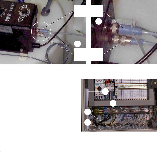
3.3.2.3Metering Station
The pumps of the projected metering stations are connected to the power outlets (1/g).
NOTE The cable from the float switch must be inserted in the metering pump unit.
Digital input (release)
2
1
Alarm output (empty alarm)
Figure 12 Alarm output and digital input of the metering pumps
For connection of the control cables in the |
|
|
|
|
electrical switching cabinet, the blind |
|
|
|
|
connections in the flange plate (13/4) are |
|
|
1 |
|
replaced by the enclosed cable screw fittings |
|
|
||
|
|
|
||
(13/3). |
|
|
|
|
Connect the control cables in accordance with |
2 |
|||
|
|
|
||
Table 13. |
|
3 |
|
|
|
|
|
||
NOTE |
The complete connecting |
4 |
|
|
|
diagrams / plans (13/1) are located |
|
||
|
in the switch cabinet. |
|
|
|
NOTE |
The connections for signal inputs |
Figure 13 Connections, metering stations |
||
|
that are not required are bridged at |
|
|
|
|
the connecting terminal (13/2). |
|
|
|
28 |
Service Handbook 08.2004 |
 Loading...