


MINIDISC RECORDER
XM-G6
SAMPLING RATE CONVERTER
M I N I D I S C R E C O R D E R X M - G 6
REC PAUSE
REC
INSTRUCTIONS
For Customer Use:
Enter below the Model No. and Serial No. which are located either on the rear, bottom or side of the cabinet. Retain this information for future reference.
Model No.
Serial No.
LVT0378-002A
[B]
Warnings, Cautions and Others
CAUTION
To reduce the risk of electrical shocks, fire, etc.:
1.Do not remove screws, covers or cabinet.
2.Do not expose this appliance to rain or moisture.
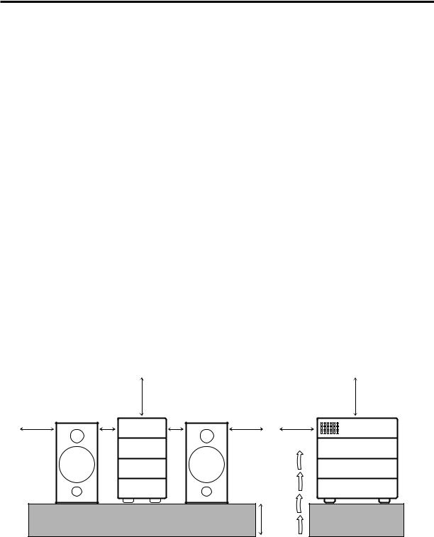
Caution: Proper Ventilation
To avoid risk of electric shock and fire, and to prevent damage, locate the apparatus as follows:
1 Front:
No obstructions and open spacing. 2 Sides/ Top/ Back:
No obstructions should be placed in the areas shown by the dimensions below.
3 Bottom:
Place on the level surface. Maintain an adequate air path for ventilation by placing on a stand with a height of 10 cm or more.
Front view |
|
|
Side view |
|
|
15 cm |
|
|
15 cm |
|
1 cm |
1 cm |
|
|
15 cm |
AX-UXG6 |
15 cm |
15 cm |
AX-UXG6 |
|
|
|
||
|
XT-UXG6R |
|
|
XT-UXG6R |
|
TD-UXG6 |
|
|
TD-UXG6 |
|
XM-G6 |
|
|
XM-G6 |
|
|
|
10 cm |
|
G-1
MPORTANT FOR LASER PRODUCTS
REPRODUCTION OF LABELS
1CLASSIFICATION LABEL, PLACED ON REAR ENCLOSURE
CLASS 1
LASER PRODUCT
2 WARNING LABEL, PLACED INSIDE THE UNIT
DANGER: Invisible laser radiation when open and interlock failed or defeated.
AVOID DIRECT EXPOSURE
TO BEAM. |
(e) |
|
|
|
|
ADVARSEL: Usynlig |
laser- |
stråling ved åbning, |
når |
sikkerhedsafbrydere er ude af funktion. Undgå udsættelse for stråling (d)
VARNING: Osynlig laserstrålning när denna del är öppnad och spärren är urkopplad. Betrakta ej strålen. (s)
VARO: Avattaessa ja suojalukitus ohitettaessa olet alttiina näkymättömälle lasersäteilylle. Älä katso säteeseen. (f)
1.CLASS 1 LASER PRODUCT
2.DANGER: Invisible laser radiation when open and interlock failed or defeated. Avoid direct exposure to beam.
3.CAUTION: Do not open the top cover. There are no user serviceable parts inside the Unit; leave all servicing to qualified service personnel.
G-2

Introduction
We would like to thank you for purchasing one of our JVC products. Before operating this unit, read this manual carefully and thoroughly to obtain the best possible performance from your unit,
and retain this manual for future reference.
Welcome to XM-G6 |
Precautions |
|
|
|
|
XM-G6 is MiniDisc Recorder exclusively designed for UXG6R micro component system. Although you cannot operate this MD recorder without UX-G6R, this integration offers enhanced features to simple and easy operations systematized on UX-G6R.
Since the basic settings and common operations are almost identical to those of UX-G6R, this manual mainly explains MD related operations. Concerning UX-G6R’s settings and operations, refer to its Instructions for details.
• The following marks are used in this manual:
Gives you warnings and cautions to prevent from a damage or risk of fire/electric shock. Also gives you information which is not good for obtaining the best possible performance from the unit.
Gives you information and hints you had better know.
Installation
•Install in a place which is level, dry and neither too hot nor too cold — between 5˚C (41˚F) and 35˚C (95˚F).
•Install the unit in a location with adequate ventilation to prevent internal heat built-up in the units.
•Leave sufficient distance between the unit and a TV.
DO NOT install the units in a location near heat 
 sources, or in a place subject to direct sunlight,
excessive dust or vibration.
Power sources
•The power source of this unit is controlled by UX-G6R’s system operation. Refer to its Instructions.
•When connecting the unit to the UX-G6R, make sure to unplug the AC power cord of the UX-G6R from the wall outlet.
Moisture condensation
Moisture may condense inside the unit in the following cases:
•After starting heating in the room
•In a damp room
•If the unit is brought directly from a cold to a warm place Should this occur, the system may malfunction. In this case, leave the unit turned on for a few hours until the moisture evaporates, unplug the AC power cord, and then plug it in again.
DO NOT disassemble the unit since there are 
 no user serviceable parts inside.
If anything goes wrong, unplug the AC power cord and consult your dealer.
1

Contents
Introduction .......................................................... |
1 |
Welcome to XM-G6 ............................................................. |
1 |
Precautions ........................................................................... |
1 |
Contents ................................................................. |
2 |
Location of the Buttons and Controls ................. |
3 |
Front Panels .......................................................................... |
4 |
Remote Control (belongs to UX-G6R) ................................ |
4 |
Getting Started ...................................................... |
5 |
Unpacking ............................................................................ |
5 |
Connecting the System Control Cable and the External |
|
Wire .................................................................................. |
5 |
Connecting Another Digital Audio Equipment .................... |
6 |
Playing Back an MD ............................................. |
7 |
Playing Back the Entire MD — Normal Play ...................... |
7 |
Searching and Skipping Tracks ............................................ |
8 |
Programing the Playing Order of the Tracks |
|
— Program Play ............................................................... |
9 |
Playing at Random — Random Play .................................. |
10 |
Repeating Tracks — Repeat Play ....................................... |
10 |
Recording onto an MD ....................................... |
11 |
Things to Know Before You Start Recording .................... |
11 |
Recording FM/AM (MW/LW) Broadcasts ........................ |
12 |
Recording a CD .................................................................. |
14 |
Recording a Tape ................................................................ |
15 |
Recording onto a Tape ........................................................ |
16 |
Recording the External Equipment .................................... |
17 |
Editing an MD ..................................................... |
19 |
Introducing MD Editing Functions .................................... |
19 |
DIVIDE Function ............................................................... |
20 |
JOIN Function .................................................................... |
21 |
MOVE Function ................................................................. |
22 |
ERASE Function ................................................................ |
22 |
ALL ERASE Function ....................................................... |
23 |
Erasing a Portion of a Track ............................................... |
23 |
Assigning Titles to an MD .................................. |
24 |
Assigning a Title ................................................................. |
24 |
Changing the Title .............................................................. |
26 |
Handling MDs ..................................................... |
27 |
MD Handling Precautions .................................................. |
27 |
Additional Information ...................................... |
28 |
MD Disc Types ................................................................... |
28 |
ATRAC (Adaptive TRansform Acoustic Coding) .............. |
28 |
UTOC (User Table Of Contents) ........................................ |
28 |
Serial Copy Management System (SCMS) ........................ |
29 |
Sound Skip Guard Memory ................................................ |
29 |
MD Messages ..................................................................... |
30 |
MD Restrictions ................................................................. |
31 |
Troubleshooting .................................................. |
32 |
Specifications ....................................................... |
32 |
2
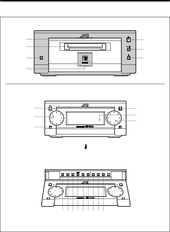
Location of the Buttons and Controls
Become familiar with the buttons and controls on the unit.
XM-G6 MiniDisc Recorder
1
2
3
4
5
SAMPLING RATE CONVERTER
6
REC PAUSE |
7 |
|
REC
AX-UXG6 |
Stereo Amplifier (belongs to UX-G6R) |
|||
|
1 |
STANDBY/ON |
|
OPEN/CLOSE |
|
|
M I C R O C O M P O N E N T |
S Y S T E M U X - G 6 R |
|
|
2 |
|
|
|
|
3 |
FM/AM |
|
AUX |
|
MULTI JOG |
MOS - FET |
VOLUME |
|
4
5
6
7
Buttons behind the Sliding Panel |
(When pressing OPEN/CLOSE button 4) |
DISPLAY |
4 |
¢ |
SET |
|
|
PLAY |
REC |
TITLE |
CLOCK |
/CHARA. |
CANCEL |
ENTER |
MODE |
MODE |
/EDIT |
/TIMER |
|||
STANDBY/ON |
|
|
|
|
|
|
|
|
OPEN/CLOSE |
|
M I C R O C O M P O N E N T |
S Y S T E M U X - G 6 R |
|
||||||
FM/AM |
|
|
|
|
|
|
|
|
AUX |
|
|
|
MOS - FET |
|
|
|
|
VOLUME |
|
89pqwerty |
|
||||||||
3

Front Panels
MiniDisc Recorder XM-G6
1 MD IN lamp (7)
2 MD loading slot (7)
3 REC PAUSE button (12)
4 REC indicator (12)
5 0(eject) button (8)
6 6(play/pause) button (8)
7 7(stop) button (8)
Stereo Amplifier |
AX-UXG6 |
1  button and STANDBY/ON lamp
2 MULTI JOG dial
3 FM/AM button (12)
4 OPEN/CLOSE button (7)
5 Display window
6 VOLUME dial
7 AUX button (17)
Buttons behind the Sliding Panel
8 DISPLAY/CHARA. button (13, 25)
9 4button (8, 9, 25) p ¢button (8, 9, 25)
q SET button (9, 13, 20, 25) w CANCEL button (9, 21, 25) e ENTER button (21, 25)
r PLAY MODE button (9) t REC MODE button (13)
y TITLE/EDIT button (20, 24)
Remote Control (belongs to UX-G6R)
*MD related operations are mainly assigned to the hollow buttons as illustrated bellow.
REMOTE CONTROL RM-SUXG6R
PANEL |
DIMMER |
|
OPEN/CLOSE |
|
|
ACTIVE |
|
SLEEP |
BASS EX. CLOCK/TIMER |
||
BASS |
TREBLE |
FM MODE |
PLAY MODE REPEAT AUTOPRESET
PTY/EON TITTLE/EDIT ENTER
DISPLAY
/CHARA. CANCEL
|
UP |
|
< |
SET |
> |
|
DOWN |
|
MD |
|
AUX |
TAPE FM/AM CD
VOLUME
• You can also use the buttons on the remote control if they have the same or similar names (or marks) as those on the units.
If operation using the remote control is different from that using each unit, it is then explained.
Concerning with the remote control
Refer to the Instructions supplied with UX-G6R.
4

Getting Started
Unpacking
After unpacking, check to be sure that you have the following items.
•Optical digital cable (1)
•External wire (1)
The number in the parentheses indicates the quantity of the pieces supplied. If any is missing, consult your dealer immediately.
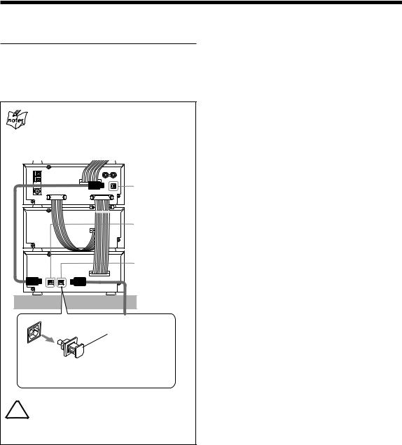
Connecting the System Control Cable and
the External Wire
Since XM-G6 Mini Disc Recorder is exclusively designed for UX-G6R micro component system, you can easily connect this unit using the system control cable and connector equipped on the rear panel of each unit as illustrated.
• To prevent malfunction, connect the external wire as illustrated.
Optical digital cable (supplied) External wire (supplied) DIGITAL OUT
AX-UXG6 |
XT-UXG6R |
FROM CONNECTOR-C |
XM-G6 |
TO CONNECTOR-C |
|
XT-UXG6R |
AUX |
|
System control cable-C |
|
Protective Plug |
Before connecting the unit, remove the protective plug from the terminal.
When connecting the XM-G6 MD recorder
Make sure to turn off UX-G6R and unplug the AC power cord. Leave it until all the connections complete.
DO NOT place XM-G6 unit or any other equipment onto AX-UXG6 stereo amplifier unit.
Damage or malfunction may result from heat generating portion of AX-UXG6.
1 Turn off UX-G6R system and unplug the AC power cord from the wall outlet.
2 Place the UX-G6R’s units onto the XM-G6 unit.
For example as follows, from top to bottom: AX-UXG6, XT-UXG6R, TD-UXG6, finally XM-G6.
3 Using the system control cable-C, connect XM-G6 unit to XT-UXG6R unit.
When connecting the system control cable to the connecter
Make sure to connect the cable to the terminal having the same name as “FROM CONNECTOR-C” and “TO CONNECTOR-C. ”
•To connect the system control cable, press the middle of the connector body until it clicks into the terminal on the rear panel.
•To disconnect, pull the connector out pushing both sides of the connector body. Never pull out the cables themselves.
To connect |
To disconnect |
||||||||||||||
|
|
|
|
|
|
|
|
|
|
|
|
|
|
|
|
|
|
|
|
|
|
|
|
|
|
|
|
|
|
|
|
|
|
|
|
|
|
|
|
|
|
|
|
|
|
|
|
4 Using the Optical digital cable, connect between XM-G6 unit and XT-UXG6R unit.
Now you have finished installation of XM-G6 unit to UX-G6R system.
5
Connecting Another Digital Audio Equipment
For digital audio recording onto an MD, XM-G6 unit connected to UX-G6R system has one more optical digital terminal (OPTICAL DIGITAL IN for AUX), prepared for an external digital audio output equipment.
When connecting another digital equipment
Make sure to turn off UX-G6R system with XM-G6 unit and unplug the AC power cord. Leave it until all the connection completes.
XT-UXG6R |
DIGITAL OUT for XM-G6
DIGITAL IN for XT-UXG6R
XM-G6 |
DIGITAL IN |
|
for AUX |
Protective Plug
Before connecting the other equipment, remove the protective plug from the terminal.
DO NOT place an external equipment onto (or 
 under) UX-G6R system and XM-G6 unit.
Damage or malfunction may result from heat generating portion of units.
1 Turn off UX-G6R system and unplug the AC power cord from the wall outlet.
2 Using the Optical digital cable (not supplied), connect between XT-UXG6R unit and another digital equipment.
Now you have finished installation to UX-G6R system.
6

Playing Back an MD
REMOTE CONTROL RM-SUXG6R
PANEL
OPEN/CLOSE DIMMER
ACTIVE |
|
SLEEP |
BASS EX. CLOCK/TIMER |
||
BASS |
TREBLE |
FM MODE |
PLAY MODE REPEAT AUTOPRESET
|
|
OPEN/CLOSE |
STANDBY/ON |
|
OPEN/CLOSE |
|
M I C R O C O M P O N E N T |
S Y S T E M U X - G 6 R |
MULTI JOG |
|
|
Play mode indicators |
|
AUX |
FM/AM |
|
|
MULTI JOG |
MOS - FET |
VOLUME |
PLAY MODE |
|
|
PTY/EON TITTLE/EDIT |
ENTER |
REPEAT |
|
|
|
|
|
|
|
|
|
|
DISPLAY |
|
CANCEL |
SET |
|
|
|
|
|
|
|
|
|
/CHARA. |
|
DISPLAY |
4 ¢ |
SET |
|
|
PLAY |
REC |
TITLE |
CLOCK |
||
|
|
|
CANCEL |
/CHARA. |
CANCEL |
ENTER |
MODE |
MODE |
/EDIT |
/TIMER |
||
|
UP |
|
|
|
|
|
|
|
|
|
|
|
< |
|
> |
UP/DOWN |
|
|
|
|
|
|
|
|
|
SET |
|
|
|
|
|
|
|
|
|
|
||
|
DOWN |
|
< / > |
4 |
¢ |
|
|
|
|
|
|
CANCEL |
|
||||
MD |
|
AUX |
MD 6 |
|
|
|||
|
|
|
DISPLAY |
|
SET |
PLAY MODE |
||
TAPE FM/AM |
CD |
(play/pause) |
|
|||||
4 / ¢ |
/CHARA. |
|
MD IN lamp |
0 (eject) |
||||
|
|
|
|
|
||||
|
|
|
|
|
|
|
|
|
7 (stop)
SAMPLING RATE CONVERTER
VOLUME
REC PAUSE
REC
MD loading slot 6 (play/pause) 7 (stop)
You can use Normal, Program, Random, or Repeat Play.
•When using the buttons behind the sliding panel, press OPEN/CLOSE button on AX-UXG6 unit to open the sliding panel first.
•When using the remote control, press MD 6 (play/ pause) button first and 7(stop) button successively.
Playing Back the Entire MD — Normal Play
1 Insert an MD into the MD loading slot.
The MD is pulled in automatically to light on the MD IN lamp orange.
• Make sure to insert an MD in the direction of arrow mark on the MD cartridge.
If you cannot insert an MD
You have inserted an MD incorrectly and taken it off by force.
MD loading slot rejects MD insertion. If this occurs, wait for one minute at most with the MD recorder turned on until a mechanical sound comes out of the MD mechanism.
The following information appears in the display window of UX-G6R as follows:
Total track number
Total playback time
7
Continued 
If the MD or each track has a title
The disc title and track titles will be shown at the lower portion of the display window (Title longer than 11 characters scrolls to show the entire title).
• DO NOT insert any foreign matters.
Searching and Skipping Tracks
While playing back an MD, you can do the following operations.
To search and skip to a particular point in a track
During playback, press and hold 4/ ¢button to meet the desired passages in a track:
2 Press 6(play/pause) button on the MD recorder or MD 6 (play/pause) button on the remote control.
Each track of the MD starts playing back, and playback information appears in the display window as follows:
Press and hold ¢button:
Fast forwards in the track.
Press and hold 4button:
Fast reverses in the track.
UP/DOWN button on the remote control is also available to search and skip operations.
Current track number
Elapsed playing time
•To stop playing back for a moment, press 6
(play/pause) button on the MD recorder.
The playback time starts blinking in the display window.
•To resume playback, press 6(play/pause) button again.
Playback continues from the point where it was stopped for a while.
3 Press 7(stop) button to stop playing back the MD.
4 Press 0(eject) button on the MD recorder to remove the MD.
• Pressing 0(eject) button during playback directly, the MD recorder stops playback and ejects the MD.
«
To go to another track
Before or during playback, press 4 / ¢ button repeatedly:
Press ¢button:
Skips to the beginning of the next and succeeding tracks.
Press 4button:
Goes back to the beginning of the current and previous tracks.
Rotating MULTI JOG dial clockwise also changes the tracks forwards quickly, while rotating it counterclockwise the tracks reverse quickly (< / > button on the remote control also available).
8
 Loading...