


 Loading...
MICRO COMPONENT SYSTEM
UX-H35— Consists of CA-UXH35 and SP-UXH35
UX-H33— Consists of CA-UXH33 and SP-UXH33
UX-H30— Consists of CA-UXH30 and SP-UXH30
MICRO COMPONENT SYSTEM
INSTRUCTIONS
For Customer Use:
Enter below the Model No. and Serial No. which are located either on the rear, bottom or side of the cabinet. Retain this information for future reference.
Model No.
Serial No.
GVT0101-008A
[B]
Warnings, Cautions and Others
IMPORTANT for the U.K.
DO NOT cut off the mains plug from this equipment. If the plug fitted is not suitable for the power points in your home or the cable is too short to reach a power point, then obtain an appropriate safety approved extension lead or consult your dealer.
BE SURE to replace the fuse only with an identical approved type, as originally fitted.
If nonetheless the mains plug is cut off ensure to remove the fuse and dispose of the plug immediately, to avoid a possible shock hazard by inadvertent connection to the mains supply.
If this product is not supplied fitted with a mains plug then follow the instructions given below:
IMPORTANT:
DO NOT make any connection to the terminal which is marked with the letter E or by the safety earth symbol or coloured green or green-and-yellow.
The wires in the mains lead on this product are coloured in accordance with the following code:
Blue : Neutral Brown : Live
As these colours may not correspond with the coloured markings identifying the terminals in your plug proceed as follows:
The wire which is coloured blue must be connected to the terminal which is marked with the letter N or coloured black.
The wire which is coloured brown must be connected to the terminal which is marked with the letter L or coloured red.
CAUTION— (standby/on) button!
Disconnect the mains plug to shut the power off completely (all lamps and indications go off). The  (standby/on) button in any position does not disconnect the mains line.
•When the unit is on standby, the STANDBY lamp lights red.
•When the unit is turned on, the STANDBY lamp goes off.
The power can be remote controlled.
CAUTION
To reduce the risk of electrical shocks, fire, etc.:
1.Do not remove screws, covers or cabinet.
2.Do not expose this appliance to rain or moisture.
CAUTION
•Do not block the ventilation openings or holes.
(If the ventilation openings or holes are blocked by a newspaper or cloth, etc., the heat may not be able to get out.)
•Do not place any naked flame sources, such as lighted candles, on the apparatus.
•When discarding batteries, environmental problems must be considered and local rules or laws governing the disposal of these batteries must be followed strictly.
•Do not expose this apparatus to rain, moisture, dripping or splashing and that no objects filled with liquids, such as vases, shall be placed on the apparatus.
IMPORTANT FOR LASER PRODUCTS
REPRODUCTION OF LABELS
1 CLASSIFICATION LABEL ON EXTERIOR SURFACE
2 WARNING LABEL INSIDE THE UNIT
CAUTION: Invisible |
laser |
|
ADVARSEL: Usynlig laser- |
|
VARNING: |
Osynlig |
laser- |
|
VARO: Avattaessa ja suo- |
||||
radiation when open |
and |
|
stråling ved åbning, når |
|
strålning när |
denna |
del |
är |
|
jalukitus |
ohitettaessa |
olet |
|
interlock failed or defeated. |
|
sikkerhedsafbrydere |
er ude |
|
öppnad och spärren är |
|
alttiina |
näkymättömälle |
|||||
AVOID DIRECT EXPOSURE |
|
af funktion. Undgå udsæt- |
|
urkopplad. |
Betrakta |
ej |
|
lasersäteilylle. Älä |
katso |
||||
TO BEAM. |
(e) |
|
telse for stråling |
(d) |
|
strålen. |
|
|
(s) |
|
säteeseen. |
(f) |
|
|
|
|
|
|
|
|
|
|
|
|
|
|
|
1.CLASS 1 LASER PRODUCT
2.CAUTION: Invisible laser radiation when open and interlock failed or defeated. Avoid direct exposure to beam.
3.CAUTION: Do not open the top cover. There are no user serviceable parts inside the unit; leave all servicing to qualified service personnel.
G-1
SAFETY INSTRUCTIONS
“SOME DOS AND DON’TS ON THE SAFE USE OF EQUIPMENT”
This equipment has been designed and manufactured to meet international safety standards, but like any electrical equipment, care must be taken if you are to obtain the best results and safety is to be assured.
Do read the operating instructions before you attempt to use the equipment.
Do ensure that all electrical connections (including the mains plug, extension leads and interconnections between pieces of equipment) are properly made and in accordance with the manufacturer’s instructions. Switch off and withdraw the mains plug when making or changing connections.
Do consult your dealer if you are ever in doubt about the installation, operation or safety of your equipment.
Do be careful with glass panels or doors on equipment.
DON’T continue to operate the equipment if you are in any doubt about it working normally, or if it is damaged in any way
—switch off, withdraw the mains plug and consult your dealer.
DON’T remove any fixed cover as this may expose dangerous voltages.
DON’T leave equipment switched on when it is unattended unless it is specifically stated that it is designed for unattended operation or has a standby mode.
Switch off using the switch on the equipment and make sure that your family know how to do this.
Special arrangements may need to be made for infirm or handicapped people.
DON’T use equipment such as personal stereos or radios so that you are distracted from the requirements of traffic safety. It is illegal to watch television whilst driving.
DON’T listen to headphones at high volume as such use can permanently damage your hearing.
DON’T obstruct the ventilation of the equipment, for example with curtains or soft furnishings.
Overheating will cause damage and shorten the life of the equipment.
DON’T use makeshift stands and NEVER fix legs with wood screws—to ensure complete safety always fit the manufacturer’s approved stand or legs with the fixings provided according to the instructions.
DON’T allow electrical equipment to be exposed to rain or moisture.
ABOVE ALL
—NEVER let anyone, especially children, push anything into holes, slots or any other opening in the case—this could result in a fatal electrical shock.
—NEVER guess or take chances with electrical equipment of any kind—it is better to be safe than sorry!
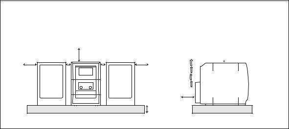
CAUTION: Proper Ventilation
To avoid risk of electric shock and fire, and to prevent damage, locate the apparatus as follows:
1 |
Front: |
No obstructions and open spacing. |
2 |
Sides/ Top/ Back: |
No obstructions should be placed in the areas shown by the dimensions below. |
3 |
Bottom: |
Place on a level surface. Maintain an adequate air path for ventilation by placing on a stand |
|
|
with a height of 10 cm or more. |
Front View |
|
15 cm |
|
15 cm |
1 cm |
1 cm |
15 cm |
|
|
|
10 cm |
UX-H35/UX-H33/UX-H30 |
|
||
Side View
15 cm
 15 cm
15 cm
UX-H35 UX-H33 UX-H30
G-2
Introduction
We would like to thank you for purchasing one of our JVC products.
Before operating this unit, read this manual carefully and thoroughly to obtain the best possible performance from your unit, and retain this manual for future reference.
About This Manual
This manual is organized as follows:
•The manual mainly explains operations using the buttons on the remote control.
You can use the buttons both on the remote control and on the main unit for the same operations if they have the same or similar names (or marks), unless mentioned otherwise.
•Basic and common information that is the same for many functions is grouped in one place, and is not repeated for each procedure. For instance, we do not repeat the information about turning on/off the unit, setting the volume, changing the sound effects, and others, which are explained in the section “Common Operations” on pages 10 and 11.
•The following symbols are used in this manual:
Gives you warning and caution to prevent damage or risk of fire/electric shock.
Furthermore, it gives you information about what is not good for obtaining the best possible performance from the unit.
Gives you information and hints you should know.
Precautions
Installation
•Install in a place which is level, dry and neither too hot nor too cold—between 5˚C and 35˚C.
•Install the unit in a location with adequate ventilation to prevent internal heat buildup in the unit.
•Leave sufficient distance between the unit and the TV.
•Keep the speakers away from the TV to avoid interference with TV.
DO NOT install the unit in a location near heat sources, or in a place subject to direct sunlight, excessive dust or vibration.
Power sources
•When unplugging the unit from the wall outlet, always pull on the plug, not the AC power cord.
DO NOT handle the AC power cord with wet hands.
Moisture condensation
Moisture may condense on the lens inside the unit in the following cases:
•After starting heating in the room
•In a damp room
•If the unit is brought directly from a cold to a warm
place
Should condensation occur, the unit may malfunction. In this case, leave the unit turned on for a few hours until the moisture evaporates, unplug the AC power cord, then plug it in again.
Others
•Should any metallic object or liquid fall into the unit, unplug the power cord and consult your dealer before operating any further.
•If you are not going to operate the unit for an extended period of time, unplug the power cord.
DO NOT disassemble the unit since there are no user serviceable parts inside.
If anything goes wrong, unplug the power cord and consult your dealer.
1

Contents
Location of the Buttons ............................................... |
3 |
Main Unit .......................................................................... |
3 |
Remote Control ................................................................. |
5 |
Getting Started ............................................................. |
6 |
Supplied Accessories ......................................................... |
6 |
Connecting Antennas ........................................................ |
6 |
Connecting Speakers ......................................................... |
7 |
Connecting Other Equipment ............................................ |
8 |
Putting the Batteries into the Remote Control .................. |
9 |
Common Operations ................................................. |
10 |
Setting the Clock ............................................................. |
10 |
Turning On the Power ..................................................... |
11 |
Adjusting the Volume ...................................................... |
11 |
Adjusting the Tone (Bass/Treble) .................................... |
11 |
Reinforcing the Bass Sound ............................................ |
11 |
Listening to FM and AM (MW) Broadcasts ........... |
12 |
Tuning in to a Station ...................................................... |
12 |
Presetting Stations ........................................................... |
12 |
Tuning in to a Preset Station ........................................... |
13 |
Receiving FM Stations with RDS ................................... |
13 |
Changing the RDS Information ...................................... |
14 |
Searching for Programs by PTY Codes (PTY Search) ... |
14 |
Switching Temporarily to a Program Type |
|
of Your Choice .......................................................... |
15 |
Playing Back Discs ..................................................... |
16 |
Playing Back the Entire Disc—Normal Play .................. |
16 |
Basic Disc Operations ..................................................... |
17 |
Programming the Playing Order of the Tracks |
|
—Program Play ......................................................... |
17 |
Playing at Random—Random Play ................................ |
18 |
Repeating Tracks—Repeat Play ...................................... |
18 |
Playing Back Tapes .................................................... |
19 |
Playing Back a Tape ........................................................ |
19 |
Recording ................................................................... |
20 |
Recording on a Tape ........................................................ |
20 |
Disc Direct Recording ..................................................... |
21 |
One Track Recording ...................................................... |
21 |
Using the Timers ........................................................ |
22 |
Using Daily Timer and Recording Timer ........................ |
22 |
Using Snooze Timer ........................................................ |
24 |
Using Sleep Timer ........................................................... |
24 |
Maintenance ............................................................... |
25 |
Troubleshooting ......................................................... |
26 |
Additional Information ............................................. |
27 |
Specifications .............................................................. |
28 |
2
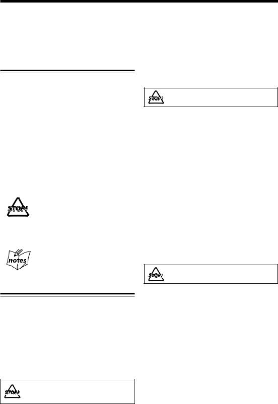
Location of the Buttons
Become familiar with the buttons on your unit.
Main Unit
Top view
1
2
3
4
5
6
PH ON E S
COMPACT
DIGITAL AUDIO
TIMER/SNOOZE |
OPEN |
ONE TOUCH |
|
MULTI CONTROL |
AHB PRO |
|
REC |
4 |
7 |
||
¢ |
||||
|
|
BAND |
VOLUME |
|
|
|
|
||
AUX |
TAPE |
TUNER |
CD |
7
8
9
p
Front view
q
w
STANDBY
MICRO COMPONENT SYSTEM
r
e
t
3
Continued
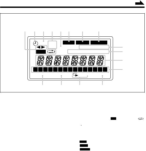
Display window
1 |
2 |
3 |
4 |
5 |
6 |
7 |
8 |
REC ON |
BASS |
SLEEP SNOOZE |
|
OFF CLOCK |
MONO STEREO |
9 |
|
REC |
RDS TA NEWS INFO |
p |
|
q
1 |
2 |
3 |
4 |
5 |
6 |
7 |
8 |
9 10 11 12 13 14 15 |
w |
PROGRAM RANDOM |
ALL |
OVER |
e |
r |
t |
y |
See the pages in parentheses for details.
Main unit
1 PHONES jack (11)
2 Disc cover
3 TIMER/SNOOZE button (10, 22 – 24)
4 ONE TOUCH REC (recording) button (20, 21)
5  (standby/on) button (11, 23)
6Source buttons
•AUX, @ #TAPE, BAND TUNER, and
#/8 CD
Pressing one of these buttons also turns on the unit.
7 MULTI CONTROL buttons
•4 (reverse skip), 7 (stop), and ¢ (forward skip)
8 AHB (Active Hyper Bass) PRO button (11)
9 0 OPEN (disc cover open) button (16) p VOLUME + / – buttons (11)
q Display window
w STANDBY lamp (11) e Cassette holder
r Remote sensor
t ) (cassette holder open) button (19 – 21)
Display window
1Tape operation indicators
• 2 3 (tape direction), REC (recording), and
(reverse mode) 2  (timer) indicator
3 REC (recording timer) indicator
4 ON/OFF (timer on-time/off-time) indicators 5 CLOCK indicator
6BASS indicator
7SLEEP indicator
8SNOOZE indicator
9 MONO and STEREO indicators
pRDS operation indicators
•RDS and TA/NEWS/INFO q Main display
•Shows the source name, frequency, etc. w Track calender indicators
e PROGRAM indicator r RANDOM indicator t Repeat indicators
• and ALL
y OVER indicator
4
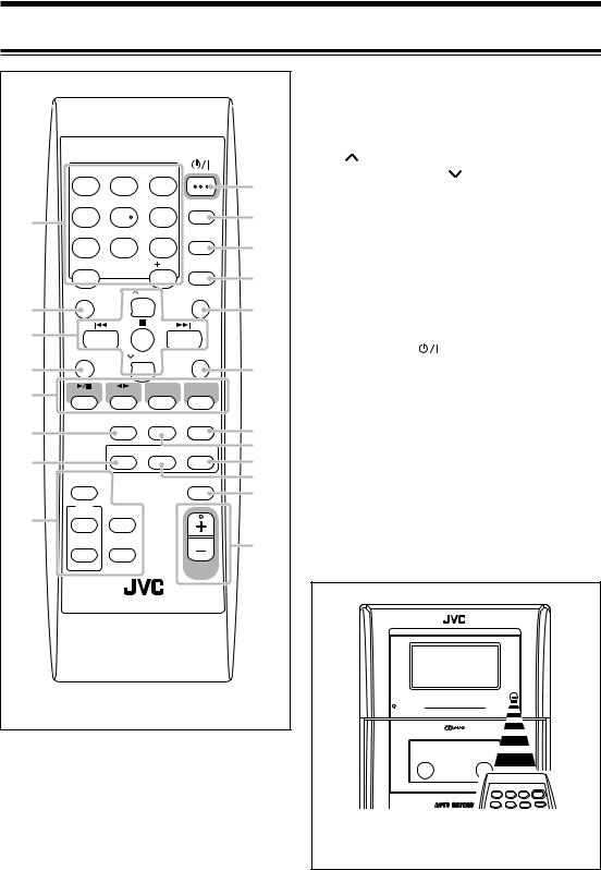
Remote Control |
|
|
|
|
|
|
|
|
||
|
|
|
|
|
|
See the pages in parentheses for details. |
||||
|
|
|
|
|
|
1 |
Number buttons |
|
|
|
|
|
|
|
|
|
2 |
BASS button (11) |
|
|
|
|
|
|
|
|
|
3 |
Multi control buttons |
|
||
|
|
|
|
STANDBY/ON |
|
|
• |
UP, 4 (reverse skip), 7 (stop), ¢ |
||
|
|
|
|
|
|
|
||||
|
1 |
2 |
3 |
|
9 |
|
|
(forward skip), and |
DOWN |
|
|
|
|
|
|
4 |
SET button (13) |
|
|
||
|
4 |
5 |
6 |
DISPLAY |
p |
5 |
Source buttons |
|
|
|
1 |
|
|
|
|
|
• 3/8 CD, 2 3 TAPE, TUNER, and AUX |
||||
7 |
8 |
9 |
CLOCK |
|
|
|||||
|
|
|
Pressing one of these buttons also turns on the |
|||||||
|
/TIMER |
q |
|
|||||||
|
|
|
|
|
|
unit. |
|
|
||
|
10 |
|
10 |
|
|
|
|
|
||
|
|
SLEEP |
|
6 |
REV.MODE (reverse mode) button (19 – 21) |
|||||
|
|
|
|
|
w |
|||||
|
|
|
|
|
7 |
PRGM (program) button (17) |
||||
|
BASS |
|
UP |
TREBLE |
|
|||||
|
|
|
8 |
RDS operation buttons (14, 15) |
||||||
|
|
|
|
|||||||
2 |
|
|
|
|
e |
|||||
|
|
|
|
|
• |
PTY SEARCH, PTY SELECT + / –, DISPLAY, |
||||
|
|
|
|
|
|
|
||||
3 |
|
|
|
|
|
|
|
and TA/NEWS/INFO |
|
|
|
SET |
DOWN |
CANCEL |
|
9 |
STANDBY/ON |
button (11, 23) |
|||
|
|
p DISPLAY button (10) |
|
|||||||
|
|
|
|
|
||||||
4 |
|
|
|
|
r |
|
||||
|
|
|
|
q CLOCK/TIMER button (10, 22, 23) |
||||||
5 |
CD |
TAPE |
TUNER |
AUX |
|
|||||
|
w SLEEP button (24) |
|
|
|||||||
|
|
|
|
|
|
|
||||
|
|
REV.MODE FM MODE |
AUTO |
|
e TREBLE button (11) |
|
||||
|
|
PRESET |
t |
r CANCEL button (18) |
|
|||||
6 |
|
|
|
|
|
|||||
|
|
PRGM |
RANDOM |
REPEAT |
y |
t AUTO PRESET button (12) |
||||
7 |
|
u |
y FM MODE button (12) |
|
||||||
|
|
|
|
|
||||||
|
PTY |
|
|
AHB PRO |
i |
u REPEAT button (18) |
|
|
||
|
SEARCH |
|
|
o |
i RANDOM button (18) |
|
||||
|
SELECT |
DISPLAY |
|
|
|
|||||
|
|
|
|
o AHB (Active Hyper Bass) PRO button (11) |
||||||
|
PTY |
|
|
|
|
|
|
|
|
|
8 |
|
|
|
|
|
; VOLUME + / – button (11) |
||||
|
+ |
|
|
|
|
|||||
|
TA/NEWS |
|
|
; |
|
|
|
|
|
|
|
|
/INFO |
|
|
|
|
|
|
|
|
|
|
|
|
|
|
|
|
|
|
|
|
– |
|
|
VOLUME |
|
|
|
|
|
|
|
|
|
|
|
|
|
|
STANDBY |
|
|
|
|
|
|
|
|
|
|
MICRO COMPONENT SYSTEM |
||
|
|
|
|
|
|
|
When using the remote control, point it at the |
|||
|
|
|
|
|
|
|
remote sensor on the front panel. |
|||
5 |
|
|
|
|
|
|
|
|
|
|
Getting Started
Continued
Supplied Accessories
Make sure that you have all the following items. The number in parentheses indicates the quantity of each piece supplied.
•AM loop antenna (1)
•FM antenna (1)
•AC power cord (1)
•Remote control (1)
•Batteries (2)
If anything is missing, consult your dealer immediately.
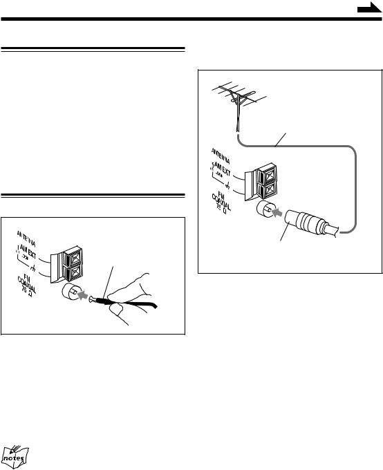
Connecting Antennas
FM antenna
FM antenna (supplied)
1Attach the FM antenna to the FM COAXIAL 75 Ω terminal.
2Extend the FM antenna.
3Fasten it up in the position which gives you the best reception, then fix it on the wall, etc.
About the supplied FM antenna
The FM antenna supplied with this unit can be used as temporary measure. If reception is poor, you can connect an outdoor FM antenna.
To connect an outdoor FM antenna
Before connecting the antenna, disconnect the supplied FM antenna.
Outdoor FM antenna (not supplied)
Coaxial cable (not supplied)
A 75 Ω antenna with coaxial type connector
(IEC or DIN 45325) should be used.
6
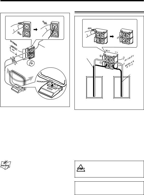
AM (MW) antenna
1 |
Vinyl-covered wire |
(not supplied) |
2 |
AM loop antenna |
(supplied) |
1Connect the AM loop antenna to the AM LOOP terminals as illustrated.
2Turn the AM loop antenna until you have the best reception.
To connect an outdoor AM (MW) antenna
When reception is poor, connect a single vinyl-covered wire to the AM EXT terminal and extend it horizontally. The AM loop antenna must remain connected.
For better reception of both FM and AM (MW)
•Make sure the antenna conductors do not touch any other terminals and connecting cords.
•Keep the antennas away from metallic parts of the unit, connecting cords, and the power cord.
Connecting Speakers
1 |
2 |
Speaker cord |
|
|
Speaker cord |
Right speaker |
Left speaker |
1Press and hold the clamp of the speaker terminal on the rear of the unit.
2Insert the end of the speaker cord into
the terminal.
Match the polarity between the unit and the speaker terminals: ª to ª and · to ·.
3Release your finger from the clamp.
•DO NOT connect speakers while the power is on.
•DO NOT connect more than one speaker to each speaker teminal.
IMPORTANT: Use only speakers with the same speaker impedance as shown on the speaker terminals on the rear of the unit.
7
Loading...