


MICRO COMPONENT SYSTEM
UX-G6R
Consists of AX-UXG6, XT-UXG6R, TD-UXG6,
and SP-UXG6.
STEREO AMPLIFIER
AX-UXG6
COMPACT DISC/TUNER
XT-UXG6R
CASSETTE DECK
TD-UXG6
SPEAKER SYSTEM
SP-UXG6
|
|
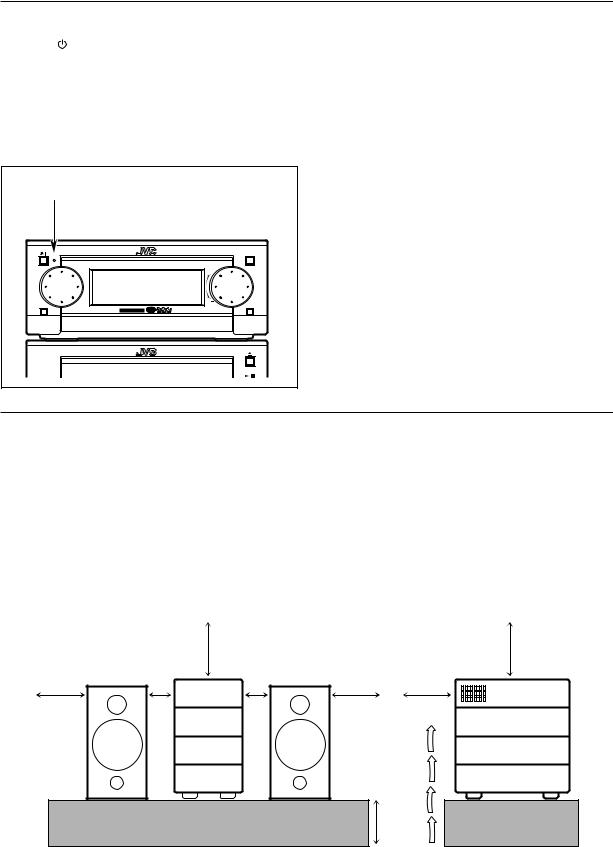
STANDBY/ON |
|
OPEN/CLOSE |
|
|
|
M I C R O C O M P O N E N T |
S Y S T E M U X - G 6 R |
|
|
FM/AM |
|
AUX |
|
|
MULTI JOG |
MOS - FET |
VOLUME |
REMOTE CONTROL RM-SUXG6E |
|
|
||
PANEL |
DIMMER |
|
|
|
OPEN/CLOSE |
|
|
|
|
|
|
|
1 B I T P • E • M D • D • C O N V E R T E R |
|
ACTIVE |
|
SLEEP |
|
|
BASS EX. CLOCK/TIMER |
|
|
||
BASS |
TREBLE |
FM MODE |
|
|
|
|
PHONES |
|
|
PLAY MODE |
REPEAT |
AUTOPRESET |
|
|
PTY/EON TITTLE/EDIT |
ENTER |
|
|
|
DISPLAY |
|
CANCEL |
|
|
/CHARA. |
|
|
|
|
|
UP |
|
|
|
< |
SET |
> |
|
|
|
DOWN |
|
|
|
MD |
|
AUX |
|
|
TAPE |
FM/AM |
CD |
|
|
|
|
DOLBY B NR |
|
|
4 |
7 |
¢ |
|
|
|
+ |
REC PAUSE |
AUTO |
|
VOLUME |
|
|
||
|
– |
|
REVERSE |
|
|
|
REC |
|
|
INSTRUCTIONS
For Customer Use:
Enter below the Model No. and Serial No. which are located either on the rear, bottom or side of the cabinet. Retain this information for future reference.
Model No.
Serial No.
LVT0376-001B
[B]
Warnings, Cautions and Others
Caution ––  switch!
Disconnect the mains plug to shut the power off completely (the STANDBY/ON lamp goes off).
The  switch in any position does not disconnect the mains line.
•When the unit is on standby, the STANDBY/ON lamp lights red.
•When the unit is turned on, the STANDBY/ON lamp lights green.
The power can be remote controlled.
CAUTION
To reduce the risk of electrical shocks, fire, etc.:
1.Do not remove screws, covers or cabinet.
2.Do not expose this appliance to rain or moisture.
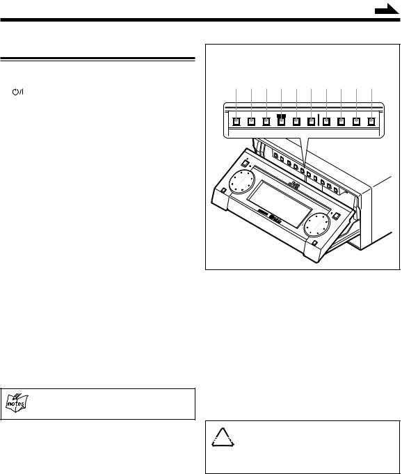
The STANDBY/ON lamp |
||
STANDBY/ON |
|
OPEN/CLOSE |
|
M I C R O C O M P O N E N T |
S Y S T E M U X - G 6 R |
FM/AM |
|
AUX |
MULTI JOG |
MOS - FET |
VOLUME |
|
1 B I T P • E • M D • D • C O N V E R T E R |
|
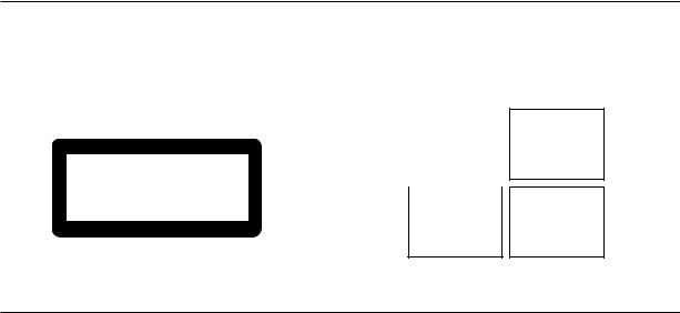
Caution: Proper Ventilation
To avoid risk of electric shock and fire, and to prevent damage, locate the apparatus as follows:
1 Front:
No obstructions and open spacing. 2 Sides/ Top/ Back:
No obstructions should be placed in the areas shown by the dimensions below.
3 Bottom:
Place on the level surface. Maintain an adequate air path for ventilation by placing on a stand with a height of 10 cm or more.
Front view |
15 cm |
|
Side view |
15 cm |
|
|
|
||
|
1 cm |
1 cm |
|
|
15 cm |
AX-UXG6 |
15 cm |
15 cm |
AX-UXG6 |
|
|
|
||
|
XT-UXG6R |
|
|
XT-UXG6R |
|
TD-UXG6 |
|
|
TD-UXG6 |
|
XM-G6 |
|
|
XM-G6 |
|
|
|
10 cm |
|
– G-1 –
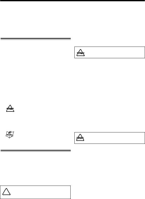
IMPORTANT FOR LASER PRODUCTS
REPRODUCTION OF LABELS
1CLASSIFICATION LABEL, PLACED ON EXTERIOR SURFACE
CLASS 1
LASER PRODUCT
2 WARNING LABEL, PLACED INSIDE THE UNIT
DANGER: |
Invisible |
laser |
radiation |
when open |
and |
interlock failed or defeated. |
||
AVOID DIRECT EXPOSURE |
||
TO BEAM. |
|
(e) |
|
|
|
|
|
|
ADVARSEL: Usynlig |
laser- |
|
stråling ved åbning, |
når |
|
sikkerhedsafbrydere er ude af funktion. Undgå udsættelse for stråling (d)
VARNING: Osynlig laserstrålning när denna del är öppnad och spärren är urkopplad. Betrakta ej strålen. (s)
VARO: Avattaessa ja suojalukitus ohitettaessa olet alttiina näkymättömälle lasersäteilylle. Älä katso säteeseen. (f)
1.CLASS 1 LASER PRODUCT
2.DANGER: Invisible laser radiation when open and interlock failed or defeated. Avoid direct exposure to beam.
3.CAUTION: Do not open the top cover. There are no user serviceable parts inside the Unit; leave all servicing to qualified service personnel.
– G-2 –
Introduction
We would like to thank you for purchasing one of our JVC products. Before operating this micro component system, read this manual carefully and thoroughly to obtain the best possible performance from your system, and retain this manual for future reference.
About This Manual
This manual is organized as follows:
•The manual mainly explains operations using the buttons and controls on the units. You can also use the buttons on the remote control if they have the same or similar names (or marks) as those on the units.
If operation using the remote control is different from that using each unit, it is then explained.
•Basic and common information that is the same for many functions is grouped in one place, and is not repeated in each procedure. For instance, we do not repeat the information about turning on/off the system, setting the volume, changing the sound effects, and others, which are explained in the section “Basic Settings” and “Common Operations” on pages 10 to 13.
•The following marks are used in this manual:
Gives you warnings and cautions to prevent from a damage or risk of fire/ electric shock.
Also gives you information which is not good for obtaining the best possible performance from the units.
Gives you information and hints you had better know.
Precautions
Installation
•Install in a place which is level, dry and neither too hot nor too cold — between 5˚C (41˚F) and 35˚C (95˚F).
•Install the units in a location with adequate ventilation to prevent internal heat buildup in the units.
•Leave sufficient distance between the units and the TV.
•Keep the speakers away from the TV to avoid interference with TV.
DO NOT install the units in a location near heat 
 sources, or in a place subject to direct sunlight,
excessive dust or vibration.
Power sources
• When unplugging from the wall outlet, always pull the plug, not the AC power cord.
DO NOT handle the AC power cord with wet hands.
Moisture condensation
Moisture may condense on the lens inside the units in the following cases:
•After starting heating in the room
•In a damp room
•If the units are brought directly from a cold to a warm place
Should this occur, the system may malfunction. In this case, leave the units turned on for a few hours until the moisture evaporates, unplug the AC power cord, and then plug it in again.
Others
•Should any metallic object or liquid fall into a unit, unplug the units and consult your dealer before operating any further.
•If you are not going to operate the units for an extended period of time, unplug the AC power cord from the wall outlet.
DO NOT disassemble the units since there are no user serviceable parts inside.
If anything goes wrong, unplug the AC power cord and consult your dealer.
1

Contents
Introduction .......................................................... |
1 |
About This Manual ............................................................... |
1 |
Precautions ........................................................................... |
1 |
Contents ................................................................. |
2 |
Location of the Buttons and Controls ................. |
3 |
Front Panels .......................................................................... |
4 |
Remote Control .................................................................... |
5 |
Getting Started ...................................................... |
6 |
Unpacking ............................................................................ |
6 |
Putting the Batteries into the Remote Control ..................... |
6 |
Connecting the System Control Cables and the External |
|
Wire .................................................................................. |
6 |
Connecting MD Recorder XM-G6 ....................................... |
7 |
Connecting Sub Woofer System ........................................... |
7 |
Connecting Antennas ............................................................ |
7 |
Connecting Speakers ............................................................ |
8 |
Connecting Other Equipments ............................................. |
9 |
Basic Settings ...................................................... |
10 |
Setting the Clock ................................................................ |
10 |
Setting the Display Illumination (Dimmer) ....................... |
10 |
Common Operations .......................................... |
11 |
Turning On the Power and Selecting the Sources .............. |
11 |
Adjusting the Volume ......................................................... |
11 |
Reinforcing the Bass Sound ............................................... |
12 |
Adjusting Bass and Treble Sounds ..................................... |
12 |
Operating the Sliding Panel ................................................ |
13 |
Listening to the External Equipment .................................. |
13 |
Listening to FM and AM Broadcasts ................ |
14 |
Tuning in a Station ............................................................. |
14 |
Presetting Stations .............................................................. |
15 |
Receiving FM Stations with RDS ...................... |
16 |
Changing the RDS Information .......................................... |
16 |
Searching for Programs by PTY Codes (PTY Search) ....... |
17 |
Switching to a Program Type Temporarily ......................... |
17 |
Playing Back a CD .............................................. |
20 |
Playing Back the Entire Disc — Normal Play ................... |
20 |
Searching and Skipping Tracks .......................................... |
21 |
Programing the Playing Order of the Tracks |
|
— Program Play ............................................................. |
21 |
Playing at Random — Random Play .................................. |
23 |
Repeating Tracks — Repeat Play ....................................... |
23 |
Playing Back a Tape ........................................... |
24 |
Playing Back a Tape — Basic Operation ........................... |
24 |
Fast-Winding a Tape ........................................................... |
25 |
Searching and Skipping to Each Program |
|
— Music Scan ................................................................ |
25 |
Playing Back Dolby-Recorded Tape .................................. |
25 |
Recording onto a Tape ........................................ |
26 |
Manual Recording onto a Tape ........................................... |
26 |
Recording in Auto Reverse ................................................ |
27 |
Synchronized Recording from a CD .................................. |
28 |
Recording from the external equipment ............................. |
28 |
Using the Timers ................................................. |
29 |
Using Recording Timer ...................................................... |
29 |
Using Daily Timer .............................................................. |
30 |
Using Sleep Timer .............................................................. |
32 |
Timer Priority ..................................................................... |
32 |
Maintenance and Additional Information ........ |
33 |
Handling CDs ..................................................................... |
33 |
Handling Cassette Tapes .................................................... |
34 |
Types of Cassette Tapes ...................................................... |
34 |
Troubleshooting .................................................. |
35 |
Specifications ....................................................... |
36 |
2
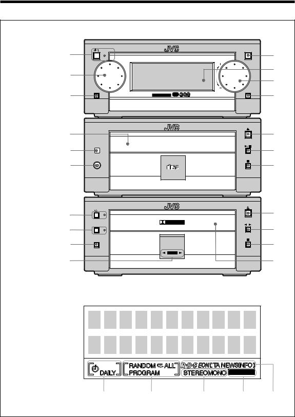
Location of the Buttons and Controls
Become familiar with the buttons and controls on the units.
Front Panels
AX-UXG6
Stereo Amplifier
1
2
3
STANDBY/ON |
OPEN/CLOSE |
M I C R O C O M P O N E N T |
S Y S T E M U X - G 6 R |
FM/AM |
|
AUX |
MULTI JOG |
MOS - FET |
VOLUME |
4
5
6
7
XT-UXG6R
Compact Disc
/Tuner
8
9 p
PHONES
1 B I T P • E • M D • D • C O N V E R T E R
COMPACT
DIGITAL AUDIO
q w e
TD-UXG6
Cassette Deck
r t y u
DOLBY B NR
REC PAUSE
AUTO |
REVERSE |
REC |
i o
;
a
Display window
REC |
|
|
BASS |
|
|
|
|
|
|
1 |
2 |
3 |
4 |
5 |
3
|
|
|
|
|
|
|
|
|
|
|
|
|
|
|
|
|
|
|
|
|
|
|
|
|
|
|
|
|
Continued |
||
Front Panels |
Buttons behind the sliding panel |
|
|
||||||||||||||||||||||||||||
|
|
|
|
|
|||||||||||||||||||||||||||
AX-UXG6 |
Stereo Amplifier |
1 2 3 4 5 6 7 8 9 p |
|||||||||||||||||||||||||||||
1 |
button and STANDBY/ON lamp (11)* |
|
|
|
|
|
|
|
|
|
|
|
|
|
|
|
|
|
|
|
|
|
|
|
|
|
|
|
|
|
|
2 |
MULTI JOG dial |
|
|
|
|
|
|
|
|
|
|
|
|
|
|
|
|
|
|
|
|
|
|
|
|
|
|
|
|
|
|
3 |
FM/AM button (14)* |
/CHARA. |
4 |
¢ |
|
|
SET |
|
|
CANCEL |
|
ENTER |
MODE |
MODE |
/EDIT |
/TIMER |
|||||||||||||||
|
|
|
DISPLAY |
|
|
|
|
|
|
|
|
|
|
|
|
|
|
|
|
|
|
|
|
|
|
|
PLAY |
REC |
TITLE |
CLOCK |
|
4 |
OPEN/CLOSE button (13)* |
|
|
|
|
|
|
|
|
|
|
|
|
|
|
|
|
|
|
|
|
|
|
|
|
|
|
|
|
|
|
5 |
Display window |
|
|
|
|
|
|
|
|
|
|
|
|
|
|
|
|
|
|
|
|
|
|
|
|
|
|
|
|
|
|
6 |
VOLUME dial (11) |
|
|
|
|
|
|
|
|
|
|
|
|
|
|
|
|
|
|
|
|
|
|
|
|
|
|
|
|
|
|
7 |
AUX button (13, 28)* |
|
|
|
|
|
|
|
|
|
|
|
|
|
|
|
|
|
|
|
|
|
|
|
|
|
|
|
|
|
|
|
|
|
|
|
STANDBY/ON |
|
|
|
|
|
|
|
|
|
|
|
|
|
|
|
|
|
|
|
|
|
|
|
|
|
|
XT-UXG6R |
Compact Disc/Tuner |
|
|
|
M I |
C |
R |
|
|
|
|
|
|
|
|
|
|
|
|
|
|
|
|
|
|
|
|
|
|
|
|
|
|
|
|
|
O |
|
|
|
|
|
|
|
|
|
|
|
|
|
|
|
|
|
|
|
|
|
|
||||
FM/AM |
|
|
|
|
|
C |
O |
M |
|
O |
N |
E |
|
|
|
|
|
|
|
|
|
|
|
|
|
|
|
|
|||
|
|
|
|
|
|
|
|
|
|
P |
|
|
|
|
|
|
|
|
|
|
|
|
|
|
|
|
|
|
|
||
|
|
|
|
|
|
|
|
|
|
|
|
|
|
|
|
|
|
|
|
|
|
|
|
|
|
|
|
|
|
|
|
8 |
CD tray |
|
|
|
|
|
|
|
|
|
|
|
|
|
|
N |
T |
|
|
|
|
|
|
|
|
|
|
|
|
|
|
|
MULTI |
|
|
|
|
|
|
|
|
|
|
|
|
|
S |
Y |
S |
|
E M |
|
|
|
|
|
|
|
|
|
|
||
|
|
|
|
|
|
|
|
|
|
|
|
|
|
|
|
|
|
T |
|
|
|
|
|
|
|
|
|
|
|
||
|
|
|
|
|
|
|
|
|
|
|
|
|
|
|
|
|
|
|
|
|
|
|
|
|
|
|
|
|
|
|
|
9 |
Remote sensor (5) |
|
JOG |
|
|
|
|
|
|
|
|
|
|
|
|
|
|
|
|
|
U |
X |
|
|
|
|
|
|
|
|
|
|
|
|
|
|
|
|
|
|
|
|
|
|
|
|
|
|
|
|
|
- |
G |
6 |
|
|
|
|
|
||||
|
|
|
|
|
|
|
|
|
|
|
|
|
|
|
|
|
|
|
|
|
|
|
|
|
|
R |
|
|
|
|
|
|
|
|
|
|
|
|
|
|
|
|
|
|
|
|
|
|
|
|
|
|
|
|
|
|
|
|
|
OPEN/CLOSE |
|
|
|
|
|
|
|
|
|
FET |
|
|
|
|
|
|
|
|
|
|
|
|
|
|
|
|
|
|
|
|
|
|
|
|
|
p |
PHONES jack (12) |
|
|
|
MOS - |
|
|
|
|
|
|
|
|
|
|
|
|
|
|
|
|
|
|
|
|
|
|
|
|
|
|
|
|
|
|
|
|
|
|
|
|
|
|
|
|
|
|
|
|
|
|
|
|
|
|
|
|
|
|
|
|||
q 0(open/close) button for CD tray (20)* |
|
|
|
|
|
|
|
|
|
|
|
|
|
|
|
|
|
|
|
|
|
|
|
|
|
|
|
|
|
||
w |
6(play/pause) button (21)* |
|
|
|
|
|
|
|
|
|
|
|
|
|
|
|
|
|
|
VOLUME |
|
|
|
|
|
|
|
|
|
|
|
|
|
|
|
|
|
|
|
|
|
|
|
|
|
|
|
|
|
|
|
|
|
|
|
AUX |
|
|
|
|
|||
e 7(stop) button (21) |
|
|
|
|
|
|
|
|
|
|
|
|
|
|
|
|
|
|
|
|
|
|
|
|
|
|
|
|
|
||
TD-UXG6 |
Cassette Deck |
r (auto-reverse) button and lamp (24, 27) t DOLBY B NR button and lamp (25, 27) y REC PAUSE button (26)
uTape operations indicators (24, 26)
•Tape direction (2/ 3) and REC indicators i 0(open/close) button for Tape tray (24)*
o `(playback) button (24)* ; 7(stop) button (25)
a Tape tray
To press the buttons suffixed with * mark also turns on the system.
Display window
1Timer mode indicators
• REC (recording timer) and
  DAILY (daily timer) indicators
2 CD playback mode indicators
• PROGRAM, RANDOM,  (repeat 1), and
  (repeat all) mode indicators
3FM mode indicators
•STEREO and MONO indicators 4 BASS indicator
5 RDS mode indicators
•RDS, EON, and TA / NEWS / INFO indicators
1 DISPLAY/CHARA. button (16)
2 4button (14, 21, 22, 25)
3 ¢button (14, 21, 22, 25)
4 SET button (22, 29)
5 CANCEL button (10, 22, 29)
6 ENTER button **
7 PLAY MODE button (21)
8 REC MODE button (28)
9 TITLE/EDIT button **
pCLOCK/TIMER button (10, 29)
**Used only with MiniDisc recorder XM-G6 (not supplied).
• DO NOT operate any button and control until 
 the system setup is completed.
• DO NOT operate the sliding panel by hands, otherwise it will cause serious damages on the sliding mechanism (see page 13).
4
 Continued
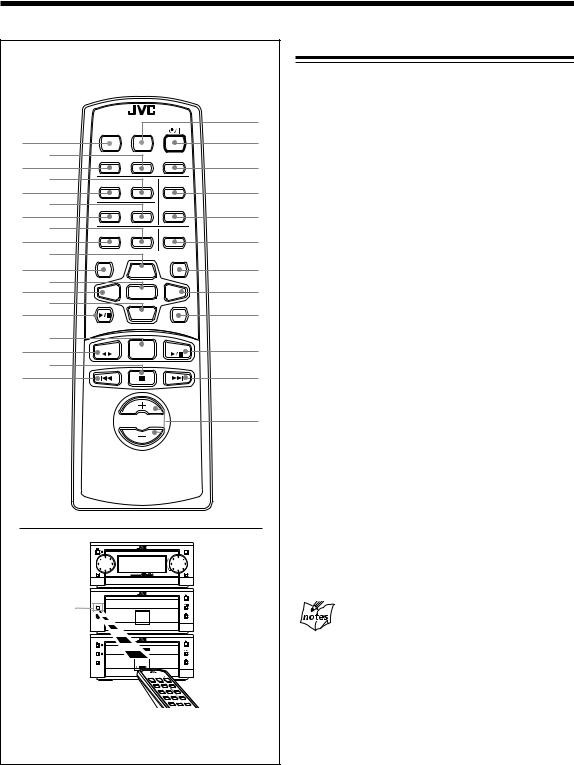
Become familiar with the buttons on the remote control.
Remote Control
|
|
REMOTE CONTROL RM-SUXG6R |
; |
||
|
|
PANEL |
|
|
|
|
|
OPEN/CLOSE DIMMER |
|
|
|
|
|
|
|
a |
|
1 |
|
|
|
|
|
2 |
ACTIVE |
|
SLEEP |
|
|
BASS EX. CLOCK/TIMER |
s |
||||
3 |
4 |
|
|
|
|
|
BASS |
TREBLE |
FM MODE |
|
|
5 |
6 |
|
|
|
d |
|
PLAY MODE REPEAT |
AUTOPRESET |
f |
||
7 |
8 |
|
|
|
|
|
PTY/EON TITTLE/EDIT |
ENTER |
|
||
9 |
p |
DISPLAY |
|
|
g |
|
|
CANCEL |
|
||
|
/CHARA. |
|
|
||
|
|
UP |
|
h |
|
q |
|
|
|
|
|
w |
< |
SET |
> |
j |
|
e |
r |
|
|||
|
|
|
|
|
k |
t |
|
|
DOWN |
|
|
|
|
|
|
|
|
|
|
MD |
|
AUX |
|
u |
|
|
|
|
l |
y |
TAPE |
FM/AM |
CD |
|
|
i |
|
|
|
/ |
|
o |
|
|
|
|
|
|
|
|
VOLUME |
|
z |
MOS - FET
Remote
Sensor
AUTO
REVERSE
PTY/EON
When using the remote control, point it at the remote sensor on the front panel.
Remote Control
1 PANEL OPEN/CLOSE button (13)
2 CLOCK/TIMER button (10, 29)
3 ACTIVE BASS EX. (extension) button (12)
4 TREBLE button (12)
5 BASS button (12)
6 REPEAT button (23)
7 PLAY MODE button (21)
8 TITLE/EDIT button *
9 PTY/EON button (17) p UP button (12, 14, 21)
q DISPLAY/CHARA. button (16) w SET button (22, 29)
e < (left cursor) button (10, 21, 29) r DOWN button (12, 14, 21)
t MD 6(play/pause) button * y FM/AM button (14)
u TAPE `(playback) button (24) i 7(stop) button (21, 25)
o 4button (14, 21, 22, 25) ; DIMMER button (10)
a  (standby/on) button (11) s SLEEP button (32)
d FM MODE button (15)
f AUTO PRESET button (15) g ENTER button *
h CANCEL button (10, 22, 29)
j > (right cursor) button (10, 21, 29) k AUX button (13, 28)
l CD 6(play/pause) button (21) / ¢button (14, 21, 22, 25)
zVOLUME +/– button (11)
*Used only with MiniDisc recorder XM-G6 (not supplied).
To operate the system correctly using the remote control
Before using these buttons:
For Tuner operations, press FM/AM button on the remote control first.
For CD operations, press CD 6(play/pause) button on the remote control first.
For Tape operations, press TAPE 23(playback) button on the remote control first.
5
Getting Started
Unpacking
After unpacking, check to be sure that you have all the following items.
The number in the parentheses indicates the quantity of the pieces supplied.
•AM loop antenna (1)
•FM antenna (1)
•Remote control (1)
•Batteries (2)
•Speaker cords (2)
•External wire (1)
If any is missing, consult your dealer immediately.
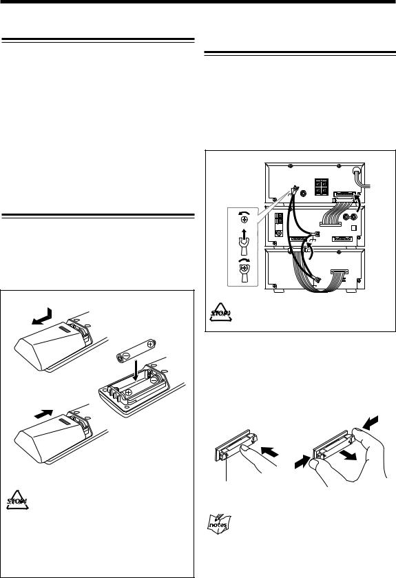
Putting the Batteries into the Remote Control
Insert the batteries — R6P (SUM-3)/AA (15F) — into the remote control, by matching the polarity (+ and –) on the batteries with the + and – markings on the battery compartment.
When the remote control can no longer operate the units, replace both batteries at the same time.
1
R6P(SUM-3)/AA(15F)
2
3
•DO NOT use an old battery together with a new one.
•DO NOT use different types of batteries together.
•DO NOT expose batteries to heat or flame.
•DO NOT leave the batteries in the battery compartment when you are not going to use the remote control for an extended period of time. Otherwise, it will be damaged from battery leakage.
Connecting the System Control Cables and
the External Wire
UX-G6R micro component system consists of three units, AX-UXG6 Stereo Amplifier, XT-UXG6R Compact Disc/ Tuner, TD-UXG6 Cassette Deck, and SP-UXG6 Speaker System.
You can easily connect these units using the system control cables equipped on the rear panel of the units.
• To prevent malfunction, connect the external wire as
illustrated. |
|
|
AX-UXG6 |
External wire |
FROM CONNECTOR-A |
(supplied) |
|
1 |
XT-UXG6R |
|
TO CONNECTOR-A |
2 |
FROM CONNECTOR-B |
|
|
3 |
TD-UXG6 |
|
TO CONNECTOR-B |
DO NOT change vertical stacking order of the |
|
units as illustrated to avoid heat buildup. |
|
•To connect the cables, press the middle of the connector body until it clicks into the connector on the rear panel.
•To disconnect, if needed, pull the connector out pushing both sides of the connector body. Never pull out the cables themselves.
To connect |
|
To disconnect |
||||||||||||||
|
||||||||||||||||
|
|
|
|
|
|
|
|
|
|
|
|
|
|
|
|
|
|
|
|
|
|
|
|
|
|
|
|
|
|
|
|
|
|
|
|
|
|
|
|
|
|
|
|
|
|
|
|
|
|
|
|
|
|
|
|
|
|
|
|
|
|
|
|
|
|
|
|
When connecting the system control cables to the connectors
Make sure to connect the cable to the connector having the same name such as “ FROM
CONNECTOR-A” and “ TO CONNECTOR-A.”
6
 Continued
Connecting MD Recorder XM-G6 |
Connecting Antennas |
|
|
|
|
You can also connect the MD recorder XM-G6 (not supplied), specifically designed for UX-G6R. This unit will complete UX-G6R micro component system.
When you connect and use this unit, refer to the Instructions supplied with it for details.
Supplied FM antenna
ANTENNA
External wire
(supplied with XM-G6)
AX-UXG6
External wire
(supplied with UX-G6R)
XT-UXG6R
FROM CONNECTOR-C
XM-G6
TO CONNECTOR-C
Optical digital cable (supplied with XM-G6)
• DO NOT install XM-G6 until you turn off the 
 system and unplug the AC power code, otherwise
installation should fail to damage the system.
• DO NOT change the vertical stacking order of XMG6 as illustrated to avoid heat buildup.
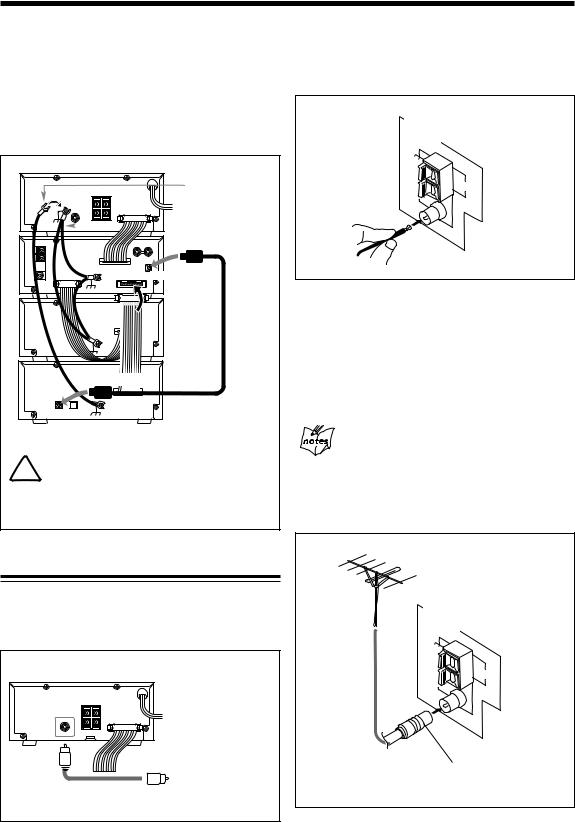
Connecting Sub Woofer System
When using JVC external sub woofer system, connect audio cable between AX-UXG6’s SUB WOOFER OUT jack and the input of your sub woofer system.
FM |
AM |
LOOP |
|
COAXIAL |
|
1 Attach the FM antenna to the FM 75 Ω COAXIAL terminal on the rear panel of XT-UXG6R.
2 Extend the FM antenna.
3 Fasten it up in the position which gives you the best reception.
About the supplied FM antenna
The FM antenna supplied with this unit can only be used as temporary measure. If reception is poor, you can connect an outdoor FM antenna.
To connect an outdoor FM antenna
Before connecting it, disconnect the supplied FM antenna.
Outdoor FM antenna
(not supplied)
ANTENNA
SUBWOOFER OUT
AX-UXG6 |
AX-UXG6 |
FM 75 |
AM |
LOOP |
|
COAXIAL |
|
|
|
Sub Woofer System |
A 75Ω antenna with coaxial type connector |
|
|||
|
|
(not supplied) |
(DIN 45325) should be used. |
|
|
Audio cable (not supplied)
7
Continued 
AM antenna
ANTENNA |
Vinyl-covered wire |
|
(not supplied) |
||
|
||
|
AM |
|
|
LOOP |
|
AM |
|
|
EXT |
|
|
FM 75 |
|
|
COAXIAL |
|
|
AM loop antenna (supplied) |
||
Connecting Speakers
You can connect the speakers using the speaker cords.
1 |
2, 3 |
|
|
|
Red |
Speaker Cord |
|
Speaker Cord |
|
|
|
RIGHT |
LEFT |
SPEAKERS |
|
||
Black |
|
|
Right speaker |
|
Left speaker |
1 Connect the AM loop antenna to the AM LOOP |
1 Open the speaker terminal. |
||
terminals as illustrated. |
2 Insert the end of the speaker cord to the terminal. |
||
2 Turn the AM loop antenna until you have the best |
|||
|
Match the polarity of the speaker terminals: Red (+) |
||
reception. |
|
to red (+) and black (–) to black (–). |
|
To connect an external AM antenna |
3 Close the speaker terminal on the rear of the unit. |
||
When reception is poor, connect a single vinyl-covered |
|
|
|
|
When connecting speaker cords |
||
wire to the AM EXT terminal and extend it horizontally. |
|
||
(The AM loop antenna must remain connected.) |
|
• Make sure to connect the cords correctly following |
|
|
the right series of above steps. |
||
|
|
||
For better reception of both FM and AM |
|
During operation, wrong connection or a short |
|
|
circuit make the power turned off to protect the |
||
• Make sure the antenna conductors do not touch |
|
||
|
system. |
||
any other terminals and connecting cables. |
|
||
|
The clock loses the setting and is reset to “0:00”. |
||
• Keep the antennas away from metallic parts of |
|
||
|
Also the MD recording may fail. |
||
the units, connecting cables, and the AC power |
|
||
|
• Use only speakers with the same speaker |
||
cord. |
|
||
|
impedance as indicated by the speaker terminals |
||
|
|
||
|
|
on the rear of the unit. |
|
|
|
|
|
8
 Continued
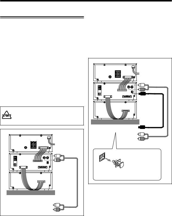
Connecting Other Equipments
You can connect the following equipments to the system:
•Audio equipment — used only as an analog playback device.
•Audio equipment with an optical digital input terminal
—used as a digital recording device.
When you connect and use these equipments, refer also to the manuals supplied with them.
To connect audio equipment without a digital output terminal
Connect the audio output jacks on the other equipment and the ANALOG IN jacks, using an audio cable (not supplied).
Be sure that the plugs of the audio cables and the jacks on the rear panel of the unit are color coded: White plugs and jacks are for left audio signals, and red ones for right audio signals.
• DO NOT connect other equipment while the power is on.
• DO NOT plug in any equipment until all connections are complete.
(AC wall outlet) |
To ANALOG IN |
XT-UXG6R |
To audio output |
on the other equipment |
• By using audio cable (not supplied), connect between the audio output jacks on the other equipment and the ANALOG IN jacks.
To connect audio equipment with an optical digital input terminal
By using both an optical digital cable (not supplied) and an audio cable (not supplied), connect:
•Between the optical digital input terminal on the other equipment and the optical digital output terminal on XTUXG6R.
•Between the audio output jacks on the other equipment and the ANALOG IN jacks.
(AC wall outlet) |
To ANALOG IN |
XT-UXG6R |
To DIGITAL OUT
To optical digital input
To audio output
 Protective Plug
Before connecting the other equipment, remove the protective plug from the terminal.
NOW, you can plug in the system and other connected equipment FINALLY!
When connecting the AC power cord into a wall outlet, the system switches to standby mode with STANDBY/ON lamp lit red.
9
 Loading...