


DVD DIGITAL CINEMA SYSTEM
English
TH-R1
Consists of XV-THR1, SP-PWR1, SP-THS55F,
SP-THS55C and SP-THS55S
ENTER
|
1 |
2 |
3 |
|
4 |
5 |
6 |
|
7 |
8 |
9 |
|
|
0 |
|
VOL |
SOURCE |
|
|


 17
17
TH-R3
Consists of XV-THR3, SP-PWR3,
SP-THS66F, SP-THS66C and
SP-THS66S
|
|
1 |
2 |
3 |
|
|
4 |
5 |
6 |
|
|
7 |
8 |
9 |
|
|
|
0 |
|
ENTER |
VOL |
SOURCE |
|
|
|
|
|


 b
b
INSTRUCTIONS
LVT1352-004A [EU]

SAFETY FIRST

 Safety Precautions
The rating plate and the safety caution are on the rear of the unit.
WARNING: DANGEROUS VOLTAGE INSIDE WARNING: TO PREVENT FIRE OR SHOCK HAZARD,
DO NOT EXPOSE THIS UNIT TO RAIN OR MOISTURE.
CAUTION:
A UNIT IS A CLASS 1 LASER PRODUCT. HOWEVER THIS UNIT USES A VISIBLE LASER BEAM WHICH COULD CAUSE HAZARDOUS RADIATION EXPOSURE IF DIRECTED. BE SURE TO OPERATE THE UNIT CORRECTLY AS INSTRUCTED.
WHEN THIS UNIT IS PLUGGED INTO THE WALL OUTLET, DO NOT PLACE YOUR EYES CLOSE TO THE OPENING OF THE DISC TRAY AND OTHER OPENINGS TO LOOK INTO THE INSIDE OF THIS UNIT.
USE OF CONTROLS OR ADJUSTMENTS OR PERFORMANCE OF PROCEDURES OTHER THAN THOSE SPECIFIED HEREIN MAY RESULT IN HAZARDOUS RADIATION EXPOSURE.
DO NOT OPEN COVERS AND DO NOT REPAIR YOURSELF. REFER SERVICING TO QUALIFIED PERSONNEL.
CLASS 1 LASER PRODUCT
REPRODUCTION OF LABELS
WARNING LABEL INSIDE OF THE UNIT
CAUTION:
8When you are not using the unit for a long period of time, it is recommended that you disconnect the power cord from the
mains outlet.
8Dangerous voltage inside. Refer internal servicing to qualified service personnel. To prevent electric shock or fire hazard, remove the power cord from the mains outlet prior to connecting or disconnecting any signal lead or aerial.
CAUTION (SP-PWR1/SP-PWR3)
The power supply to the subwoofer is linked to the centre unit. The POWER ON lamp on the subwoofer lights green when the power is turned on.
CAUTION
●Do not block the ventilation openings or holes. (If the ventilation openings or holes are blocked by a newspaper or cloth, etc., the heat may not be able to get out.)
●Do not place any naked flame sources, such as lighted candles, on the apparatus.
●When discarding batteries, environmental problems must be considered and local rules or laws governing the disposal of these batteries must be followed strictly.
●Do not expose this apparatus to rain, moisture, dripping or splashing and that no objects filled with liquids, such as vases, shall be placed on the apparatus.
OR
IMPORTANT:
8Please read the various precautions on page G1 and G2 before installing or operating the unit.
8It should be noted that it may be unlawful to re-record prerecorded tapes, DVDs, or discs without the consent of the owner of copyright in the sound or video recording, broadcast or cable programme and in any literary, dramatic, musical, or artistic work embodied therein.
CAUTION^A button!
(XV-THR1/XV-THR3)
Disconnect the mains plug to shut the power off completely (the STANDBY lamp goes off).
The button in any position does not disconnect the mains line.
●When the system is on standby, the STANDBY lamp lights red.
●When the system is turned on, the STANDBY lamp goes off. The power can be remote controlled.
CAUTION
To avoid personal injury or accidentally dropping the unit, have two persons unpack, carry,
SP-THR3: 28.4 kg and install the unit.
CAUTION
To reduce the risk of electrical shocks, fire, etc.:
1.Do not remove screws, cover or cabinet.
2.Do not expose this appliance to rain or moisture.
G1
SAFETY FIRST
The STANDBY/ON A button does not completely shut off mains power from the unit, but switches operating current on and off. ABB shows electrical power standby and ACB shows ON.
When the equipment is installed in a cabinet or a shelf, make sure that it has sufficient space on all sides to allow for ventilation
(10 cm or more on both sides, on top and at the rear).
When discarding batteries, environmental problems must be considered and the local rules or laws governing the disposal of these batteries must be followed strictly.
Failure to heed the following precautions may result in damage to the unit, remote control or disc.
1.DO NOT place the unit ^
^in an environment prone to extreme temperatures or humidity.
^in direct sunlight.
^in a dusty environment.
^in an environment where strong magnetic fields are generated.
^on a surface that is unstable or subject to vibration.
2.DO NOT block the unit’s ventilation openings or holes.
(If the ventilation openings or holes are blocked by a newspaper or cloth, etc., the heat may not be able to get out.)
3.DO NOT place heavy objects on the unit or remote control.
4.DO NOT place anything which might spill on top of the unit or remote control.
(If water or liquid is allowed to enter this equipment, fire or electric shock may be caused.)
5.DO NOT expose the apparatus to dripping or splashing.
6.DO NOT use this equipment in a bathroom or places with water. Also DO NOT place any containers filled with water or liquids (such as cosmetics or medicines, flower vases, potted plants, cups, etc.) on top of this unit.
7.DO NOT place any naked flame sources, such as lighted candles, on the apparatus.
8.AVOID violent shocks to the unit during transport.
MOISTURE CONDENSATION
Moisture in the air will condense on the unit when you move it from a cold place to a warm place, or under extremely humid conditions^just as water droplets form on the surface of a glass filled with cold liquid. In conditions where condensation may occur, disconnect the unit’s power plug from the wall and keep it disconnected for a few hours to let the moisture dry, then turn on the unit.
DISCLAIMER OF LIABILITY
JVC shall not be liable for any loss relating to the unit’s failure to properly record, store or playback any content (video, audio or otherwise) for any reason whatsoever. Any applicable warranties shall only cover replacement or repair of the effected unit, and shall not apply to recovery or replacement of lost content.
ATTENTION:
8Using a mobile phone in the vicinity of the unit may cause picture vibration on the TV screen or change the screen to a
blue back display.
8Some TVs or other appliances generate strong magnetic fields. Do not place such appliances on top of the unit as it
may cause picture disturbance.
8If there is a power outage when using the unit, the recorded data may be erased.
8Recorded programmes and data cannot be restored once the disc is damaged.
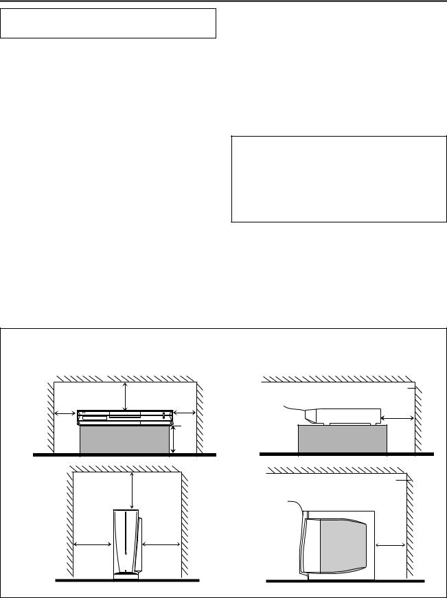
CAUTION: Proper Ventilation
To avoid risk of electric shock and fire and to protect from damage, place the apparatus on a level surface. The minimal clearances are shown below:
Wall or |
XV-THR1/ |
|
|
obstructions |
8 cm |
||
XV-THR3 |
|||
|
|||
|
3 cm |
3 cm |
|
|
|
15 cm |
Wall or |
SP-PWR1/ |
|
|
obstructions |
20 cm |
||
SP-PWR3 |
|||
|
|||
|
15 cm |
15 cm |
|
Wall or obstructions |
|
Front |
XV-THR1/XV-THR3 |
|
10 cm |
||
|
||
No |
|
|
obstructions |
|
Wall or obstructions
Front SP-PWR1/SP-PWR3
15 cm
No
obstructions
G2

CONTENTS
DISC INFORMATION |
2 |
NAVIGATION |
55 |
|
About Discs .................................................................................... |
2 |
Library Database Navigation ....................................................... |
55 |
|
INDEX |
7 |
Basic Operation Of Original Information...................................... |
56 |
|
Edit Original Information |
58 |
|||
|
|
|||
INSTALLING YOUR NEW UNIT |
11 |
Basic Operation Of Play List Information..................................... |
59 |
|
Edit Play List Information |
60 |
|||
Connecting The TV And TV Antenna |
11 |
|||
Edit Library Information |
63 |
|||
Connecting The FM And AM Antennas |
12 |
|||
Playback With MP3/JPEG Navigation |
64 |
|||
Assembling The Front And Surround Speakers |
13 |
|||
EDITING |
65 |
|||
Connecting The Satellite (Front, Centre, Surround) Speakers .... |
14 |
|||
Speaker Layout ............................................................................ |
15 |
DV Dubbing ................................................................................. |
65 |
|
Connecting The Powered Subwoofer .......................................... |
16 |
Edit From A Camcorder............................................................... |
67 |
|
Connecting To A Digital Component............................................ |
16 |
Edit To Or From Another Recorder ............................................. |
68 |
|
Connecting The Power Cord........................................................ |
16 |
Output/Input Set .......................................................................... |
69 |
|
INITIAL SETTINGS |
17 |
SYSTEM CONNECTIONS |
71 |
|
Auto Set Up.................................................................................. |
17 |
Connecting To A Satellite Receiver............................................. |
71 |
|
Preset Download.......................................................................... |
18 |
Connecting/Using A Decoder ...................................................... |
71 |
|
Language ..................................................................................... |
20 |
Remote Control Functions........................................................... |
72 |
|
Monitor Set................................................................................... |
21 |
TV Multi-Brand Remote Control .................................................. |
72 |
|
Speaker Set ................................................................................. |
22 |
Satellite Receiver Multi-Brand Remote Control ........................... |
73 |
|
BASIC OPERATIONS ON DVD DECK |
25 |
SUBSIDIARY SETTINGS |
74 |
|
Basic Playback............................................................................. |
25 |
Mode Set ..................................................................................... |
74 |
|
Adjusting The Volume .................................................................. |
26 |
Scan Mode Set ............................................................................ |
77 |
|
Listening With Headphones ......................................................... |
26 |
Tray Lock..................................................................................... |
77 |
|
Setting Auto Surround And Virtual Surround Back ...................... |
27 |
SHOWVIEW System Setup ............................................................ |
78 |
|
Playback Features ....................................................................... |
28 |
TV Tuner Set ............................................................................... |
79 |
|
Live Memory Playback ................................................................. |
32 |
Clock Set ..................................................................................... |
82 |
|
Using The On-screen Bar ............................................................ |
35 |
Format A Disc.............................................................................. |
83 |
|
Basic Recording ........................................................................... |
39 |
Finalise A Disc............................................................................. |
84 |
|
Recording Features...................................................................... |
40 |
Adjusting The Centre Tone.......................................................... |
85 |
|
Surround Mode ............................................................................ |
42 |
Subwoofer Power Control............................................................ |
85 |
|
Receiving Radio Broadcasts ........................................................ |
44 |
Adjusting The Speaker Output Using Test Tone ......................... |
85 |
|
Using The RDS (Radio Data System) When Receiving |
|
Adjusting The Equaliser Pattern .................................................. |
85 |
|
FM Stations ............................................................................... |
45 |
TROUBLESHOOTING |
86 |
|
TIMER RECORDING |
49 |
|||
ON-SCREEN MESSAGE |
89 |
|||
SHOWVIEW Timer Programming ................................................... |
49 |
|||
Manual Timer Programming......................................................... |
50 |
APPENDIX |
90 |
|
On-Disc Timer Programming |
51 |
|||
|
|
|||
Check, Cancel And Change Programmes ................................... |
53 |
SPECIFICATIONS |
92 |
|
Automatic Satellite Programme Recording |
54 |
|||
|
|
|||
|
|
LIST OF TERMS |
94 |
HOW TO USE THIS INSTRUCTION MANUAL
●All major sections and subsections are listed in the Table Of Contents on page 1. Use this when searching for information on a specific procedure or feature.
●The Index on pages 7 - 9 illustrates the controls and connections on the front and rear panel, the front display panel and the remote control.
●The list of terms on page 94 lists frequently-used terms, and the number of the page on which they are used or explained in the manual.
●The A mark signals a reference to another page for instructions or related information.
●Operation buttons necessary for the various procedures are clearly indicated through the use of illustrations at the beginning of each major section.
1
DISC INFORMATION

 About Discs
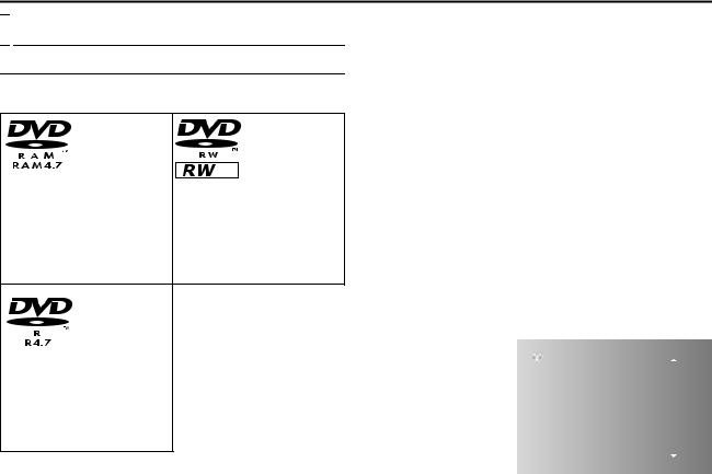
Recordable/Playable Discs
You can use discs with the following logos for recording and playback.
|
|
|
|
DVD-RAM |
DVD-RW |
||
12 cm: 4.7 GB/9.4 GB |
12 cm: 4.7 GB |
||
8 cm: 1.4 GB/2.8 GB |
8 cm: 1.4 GB |
||
Ver. 2.0/2x speed |
Ver. 1.1/1x - 2x speed |
||
Ver. 2.1/1x - 3x speed |
(Video mode/VR mode) |
||
Ver. 2.2/5x speed |
Ver. 1.2/4x/6x speed |
||
|
(Video mode/VR mode) |
||
DVD-R
12 cm: 4.7 GB
8 cm: 1.4 GB
Ver. 2.0/1x - 4x/8x speed (Video mode)
Ver. 2.1/16x speed (Video mode)
●The above table is based on the information as of February 2005.
●Recording and playback may not be performed depending on the characteristics and condition of the disc used, leading to unsatisfactory results. Using discs manufactured by JVC is recommended since they have been tested to be compatible with this unit.
DVD-RAM Discs
It is only possible to use discs which conform with DVD-RAM standard Version 2.0, 2.1 or 2.2.
●If you use a disc formatted under a different standard version, format it on this unit before use.
●It may not be possible to record, play back, edit or dub a DVD-RAM disc even if it conforms to the standard if it was recorded or edited on the devices from other manufacturers or on a PC, or if it has far too many titles, or if there is very little available capacity remaining on the disc.
●DVD-RAM discs recorded on this unit cannot be played back on an incompatible DVD player.
●It is possible to record copy-once programmes of digital broadcasts only onto 4.7/9.4 GB DVD-RAM discs. (2.8 GB DVD-RAM discs are not compatible)
●This unit does not support discs contained in cartridges. Use the disc after removing it from the cartridge. For details on discs in TYPE2 and TYPE4 (disc removable) cartridge, refer to its instruction manual.
●While recording, it is possible not only to start playback of a programme currently being recorded, but also to watch another programme previously recorded.
DVD-R/RW Discs
It is only possible to use DVD-R discs which conform with DVD-R standard Version 2.0 or 2.1.
It is only possible to use discs which conform with DVD-RW standard Version 1.1 or 1.2. Available in VR mode and Video mode.
When a DVD-R/RW disc (Video mode) is finalised (A pg. 84), it can be played back on a standard DVD player as a DVD VIDEO disc.
When a DVD-RW disc (VR mode) is finalised (A pg. 84), it can be played back on DVD player compatible with the VR mode of DVD-RW discs.
Before finalising^
it is possible to record on unrecorded areas of the disc, edit the disc title and programme titles, and delete programmes.
●It is impossible to record or edit DVD-R/RW discs recorded on other devices even if they have not been finalised.
●It is impossible to overwrite recorded areas of DVD-R discs.
●Available recording capacity does not increase even if a recorded programme is deleted from a DVD-R disc.
After finalising^
After a DVD-R/RW disc (Video mode) has been finalised, it is possible to play back the recorded programmes (video and/or audio) on a standard DVD video player as a DVD VIDEO disc. ● Edited titles are displayed
as the ADVD menuB in |
|
CONTENTS MENU |
PREV |
|
video mode. |
|
|
||
81 |
Sister Princess ED2 14/11 0:55 PR12<HDD MN26 |
16.11.2002 |
||
82 GALAXY ANGLE A#04 OP 06/10 9:30 PR12<HDD |
07.10.2002 |
|||
● It is impossible to record, |
||||
83 GALAXY ANGLE A#04 ED 06/10 9:30 PR12<HDD |
07.10.2002 |
|||
edit or delete the data |
84 |
FISHING WORLD OP 22/12 20:00 PR3 |
22.12.2002 |
|
either in video mode or in |
85 |
FISHING WORLD ED 22/12 20:00 PR3 |
22.12.2002 |
|
86 RALLY CAR OP 10/04 0:30 PR3 |
04.10.2002 |
|||
VR mode. |
87 |
RALLY CAR ED 10/04 0:30 PR3 |
04.10.2002 |
|
88 |
Chobits #04 OP 02/05 PR10 |
02.05.2002 |
||
● Either in video mode or in |
||||
89 Chobits #04 ED 02/05 PR10 |
02.05.2002 |
|||
VR mode, although the |
90 |
Chobits #25 ED 26/09 PR10 MN32 LPCM |
26.09.2002 |
|
disc can be played back |
NEXT |
|
|
on DVD players from other |
|
manufacturers, sometimes it may not be possible to play back depending on the disc and recording conditions.
●It is impossible to record on CD-R/RW or DVD-R discs used for authoring.
●When recording copy-once programmes of digital broadcasts, record in VR mode using CPRM compatible DVD-RW discs.
NOTE:
The following may result if you play back a DVD-R disc recorded on another unit.
●The disc does not play.
●A mosaic pattern (block noise) appears on the screen.
●Video or audio may be dropped out.
●The unit stops during playback.
2
DISC INFORMATION
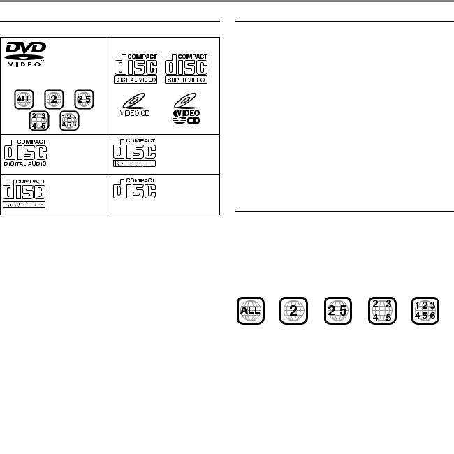
Discs For Playback Only
You can use discs with the following logos for playback only.
DVD VIDEO |
Video CD/Super Video CD |
(example of region code indications)
Audio CD |
CD-R |
CD-DA files |
CD-DA/JPEG/ |
|
MP3 files |
CD-RW |
CD-ROM |
CD-DA/JPEG/ |
JPEG/MP3 files |
MP3 files |
|
●Playback may not be performed depending on the characteristics and condition of the disc used.
●DTS Audio CDs can also be played back. (An optional DTS decoder is required)
●MP3 and JPEG discs can be played back on this unit only when they have been recorded in the ISO9660 or Joliet format and finalised.
●JPEG files that can be played back on this unit must conform to JFIF/Baseline process, and the maximum resolution of a JPEG file is 2,812 pixels in width and 2,112 pixels in height.
●CD-R/RW discs recorded in music CD format need to be finalised to play back on this unit.
●Operation and audio quality of this unit are not guaranteed for discs that do not conform to the Compact Disc specification (CD-DA).
Before you play back a CD, check for the CD logo and read the notes on the package to confirm that it conforms to the Compact Disc specification.
●Depending on the intentions of the author of the software, recording conditions of DVD discs and Video CD/SVCD discs may be restricted. Since this unit plays back discs according to the intentions of the author of the software as indicated on the disc, some functions may not operate as commanded.
●When switching from the first layer to the second layer of doublelayered DVD VIDEO discs, the image and sound may be momentarily distorted. This is not a malfunction.
●DVD-AUDIO discs compatible with DVD video players can be played.
●Super Audio CDs (SACD) compatible with conventional CD players can be played.
●It is possible to play back finalised +R/+RW (Video mode only) discs. ADVDB lights on the front display panel when a +R/+RW disc is loaded.
However, the use of +R double layer disc on this unit may not be recommended.
Unplayable Discs
The unit may not be able to play back or it may take some time to read a disc depending on the recording status or condition of the disc, or if the disc is scratched, dirty or warped.
In addition, do not attempt to play back discs in unusual shapes (heart-shaped, octagonal, or other forms). If such discs are accidentally played back, it may cause noise that can lead to speaker damage.
●CD-ROM discs (including PHOTO-CD and CD-G)
●Discs recorded in Packet Write (UDF) format
●1.3 GB double density CDs (DDCD)
●High density CDs (HDCD)
The following discs also cannot be played back.
●Discs of a region number other than A2B
●DVD-RAM (2.6 GB/5.2 GB)
●DVD-RAM (TYPE1)
Caution for DualDisc playback
The Non-DVD side of a ADualDiscB does not comply with the ACompact Disc Digital AudioB standard. Therefore, the use of NonDVD side of a DualDisc on this product may not be recommended.
Region Number
The world is divided into 6 regions for DVD VIDEO discs.
DVD VIDEO discs are assigned a region number to indicate which region they may be played back in. A disc cannot be played back on this unit unless the region number of the disc matches that of the unit. The region number for this unit is A2B. Only discs whose region number includes A2B or AALLB can be played back such as shown below.
Examples of DVD VIDEO labels which can be played back using this unit.
Marks of discs in this instruction manual
|
|
|
|
|
Allows operation with a |
|
|
|
|
Allows operation with a |
|
|
|
|
|
|
|
||||||
|
|
|
|
|
DVD-RAM disc. |
|
|
|
|
Video CD/Super Video |
|
|
|
|
|
|
|
|
|
|
|
|
CD (SVCD) disc. |
|
|
|
|
|
|
|
|
|
|||
|
|
|
|
|
Allows operation with a |
|
|
|
Allows operation with |
||
|
|
|
|
|
|
|
|||||
|
|
|
|
|
DVD-R disc. |
|
|
|
an Audio CD disc. |
||
|
|
|
|
|
Allows operation with a |
|
|
|
Allows operation with a |
||
|
|
|
|
|
|
|
|
||||
|
|
|
|
|
DVD-RW disc. |
|
|
|
disc including MP3 |
||
|
|
|
|
|
|
|
|
|
|
|
files. |
|
|
|
|
|
Allows operation with a |
|
|
|
|
Allows operation with a |
|
|
|
|
|
|
|
|
|
|
|||
|
|
|
|
|
DVD VIDEO disc. |
|
|
|
|
disc including JPEG |
|
|
|
|
|
|
|
|
|
||||
|
|
|
|
|
|
|
|
|
|
|
files. |
|
|
|
|
|
|
|
|
|
|
|
|
3
DISC INFORMATION
Recording Medium And Format
DVD-RAM
●Recording and erasing can be performed as many times as possible on a disc.
●Editing can be performed after recording, such as deleting unwanted parts.
●While recording, it is possible not only to start playback of a programme currently being recorded, but also to watch another programme previously recorded.
DVD-RW (VR mode)
●Recording and erasing can be performed as many times as possible on a disc.
●Editing can be performed after recording, such as deleting unwanted parts.
DVD-RW (Video mode)
●Can be played back on other DVD players after finalising.
●New recording can be performed by erasing all the data on a disc once played back.
DVD-R
●Can be played back on other DVD players after finalising.
●Suitable when keeping a recorded disc for a long time.
File Structure Of Discs
DVD VIDEO
Typically, DVD VIDEO discs are made up of larger units called AtitlesB. Each title has a number (title number) that can be used to select desired titles. Titles are further divided into units called AchaptersB. Each chapter has a number (chapter number) that can also be used to select desired chapters. Note that some discs are not divided into titles and chapters.
When you record a programme on a DVD-RAM/RW (VR mode) disc
A single recording session results in a single title. In addition, chapter marks are automatically inserted when recording is paused. It is also possible to insert chapter marks at desired locations during playback. (A pg. 30)
When you record a programme on a DVD-R/RW (Video mode) disc
A single recording session results in a single title. In addition, chapter marks are automatically inserted when recording is paused. It is also possible to insert chapter marks at desired locations during playback. Once the disc has been finalised, these chapter marks are deleted and new chapter marks are assigned automatically approximately every 5 minutes.
DVD-RAM, DVD-RW, DVD-R or DVD VIDEO disc
|
|
|
Title 1 |
|
|
|
|
|
|
|
|
Title 2 |
|
|
||
|
|
|
|
|
|
|
|
|
|
|
||||||
|
|
|
|
|
|
|
|
|
|
|
|
|
|
|
|
|
Chapter 1 |
|
Chapter 2 |
|
Chapter 3 |
|
|
Chapter 1 |
|
Chapter 2 |
|
Chapter 3 |
|||||
|
|
|
|
|
|
|
|
|
|
|
|
|
|
|
|
|
|
|
|
|
|
|
|
|
|
|
|
|
|
|
|
|
|
●In Video mode, even before finalising, it is impossible to perform editing operations other than changing the disc name and/or title names and deleting programmes and/or titles.
●After finalising, it is impossible to perform editing operations.
Audio CD/Video CD/SVCD
Typically, Audio CD discs are divided into separate tracks each containing one song. Each track is assigned a number. For example, the third track is Track 3. The same is true for Video CD/ SVCD discs.
However, some discs are not divided into tracks.
Audio CD/Video CD/SVCD
Track 1 |
|
|
Track 2 |
|
|
Track 3 |
|
|
Track 4 |
|||
|
|
|
||||||||||
|
|
|
|
|
|
|
|
|
|
|
|
|
|
|
|
|
|
|
|
|
|
|
|
|
|
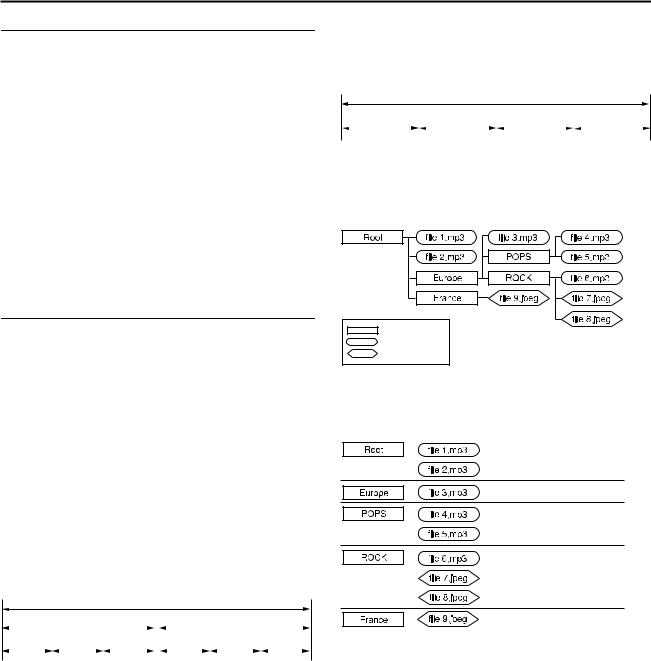
JPEG/MP3 Disc (CD-R/RW/ROM)
MP3/JPEG files put in directories nested in several levels on a disc will be organized as if they were put in single level directories (groups) by the MP3/JPEG Navigation of this unit. (A pg. 64)
File structure of a disc before starting the MP3/JPEG Navigation
Directory
MP3 file
JPEG file
File structure of the disc after starting the MP3/JPEG Navigation
Files are automatically grouped as follows and displayed on the MP3/JPEG Navigation screen. Data is displayed in the alphabetical order of file name. Files are grouped based on roots.
●This unit can recognise up to 9 hierarchies including directories and files.
Also, it can recognise up to 250 files in each group, and up to 99 groups on a disc.
NOTES:
●Video CD/SVCD discs that support Playback Control (PBC)
The contents of a disc are recorded into several hierarchies, and played back according to the instructions on the screen while navigating through the hierarchies. It is also possible to playback recorded tracks consecutively without activating the PBC function even when playing a PBC-compatible disc. (A pg. 31)
●Regarding the contents recorded on discs
Some files may not be played back depending on the file types and other factors.
4
DISC INFORMATION
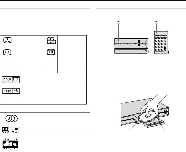
DVD VIDEO Marks |
|
Placing A Disc |
|
|
|
|
Sometimes marks are printed on a DVD disc and/or on its |
Opening the disc tray |
|
|
|
||
packaging to indicate information regarding the contents and |
Press M to open the disc tray. |
|
|
|
||
functions of the disc. Check the marks indicating the contents and |
|
|
|
|
||
functions of the disc. Note, however, that in some cases a disc may |
|
|
|
|
||
not include a mark even for a function it supports. |
|
|
|
|
||
Marks related to video |
|
OPEN/ |
|
|
|
|
|
|
DVD THEATER SYSTEM |
||||
Number of subtitles |
Number of angles |
CLOSE |
TV/INPUT |
TV |
AUDIO |
|
DVD |
FM/AM |
DBS |
TIMER |
|||
|
|
|
ABC |
DEF |
TV DIRECT |
|
|
|
1 |
2 |
3 |
|
|
|
|
GHI |
JKL |
MNO |
PROG |
|
|
|
4 |
5 |
6 |
|
|
|
|
PQRS |
TUV |
WXYZ |
PAGE |
|
Recorded under the |
Screen includes |
7 |
8 |
9 |
|
|
CANCEL |
0 |
MEMORY |
|
|||
standard 4:3 aspect |
black bands at the |
|
AUX |
MARK |
AUDIO |
|
|
|
|
TV |
|||
|
|
|
|
|
DBS |
|
|
|
G-CODE |
REC LINK |
SETTING SORROUND |
||
ratio |
top and the bottom |
● Pressing the button again closes the disc tray. |
|
|
||
|
of image which has |
|
|
|||
|
● Use the button to open and close the disc tray. |
|
|
|||
|
a standard 4:3 |
|
|
|||
|
● Do not block the disc tray with your hand while it is opening or |
|||||
|
aspect ratio (letter |
|||||
|
closing as this may result in hardware failure. |
|
|
|||
|
box) |
|
|
|||
|
● Do not place unplayable discs or any object other than a disc on |
|||||
|
|
|||||
Video playback is in Wide video mode (16:9) |
the disc tray. |
|
|
|
||
on wide televisions, but in letter box on |
● Do not press down strongly on the disc tray or place any heavy |
|||||
televisions with standard 4:3 aspect ratio. |
objects on it. |
|
|
|
||
Video playback is in Wide video mode (16:9) |
Discs without cartridges |
|
|
|
||
on wide televisions, but pan and scan is used |
|
|
|
|||
|
|
|
|
|||
on televisions with standard 4:3 aspect ratio |
|
|
|
|
||
(either the left or right side of the image is cut- |
|
|
|
|
||
out). |
|
|
|
|
|
|
Marks related to audio |
|
|
|
|
|
|
Number of audio tracks |
|
|
|
|
|
|
Dolby Digital mark |
|
|
|
|
|
|
It has been developed by Dolby Laboratories as |
Label side facing up |
Disc tray |
||||
a digital surround system. |
|
|||||
|
Place the disc on the disc tray with the label side facing up. Since |
|||||
DTS (Digital Theater Systems) |
||||||
disc size changes depending on the disc to be played back, be |
||||||
You can enjoy DTS audio if you connect an |
||||||
sure to correctly align the disc with the grooves for its size. If the |
||||||
amplifier with a built-in DTS decoder to the |
||||||
disc is not in its groove, it may be scratched or otherwise damaged. |
||||||
DIGITAL OUT connector of the unit. |
||||||
To insert an 8 cm disc, place it according to the inner groove. |
||||||
|
|
|||||
|
|
DVD-RAM discs contained in cartridges |
|
|
||
|
|
Double-sided discs: |
|
|
|
|
|
|
Remove the disc from the cartridge. Align the disc with the grooves |
||||
|
|
on the disc tray as shown in the illustration and insert with the side |
||||
|
|
you wish to play back or record facing down. If you insert the disc |
||||
|
|
with ASide AB facing down, programmes are recorded on side A. |
||||
|
|
Single-sided discs: |
|
|
|
|
|
|
Remove the disc from the cartridge. Align the disc with the grooves |
||||
|
|
on the disc tray as shown in the illustration and insert with the label |
||||
|
|
side facing up. |
|
|
|
|
5
DISC INFORMATION
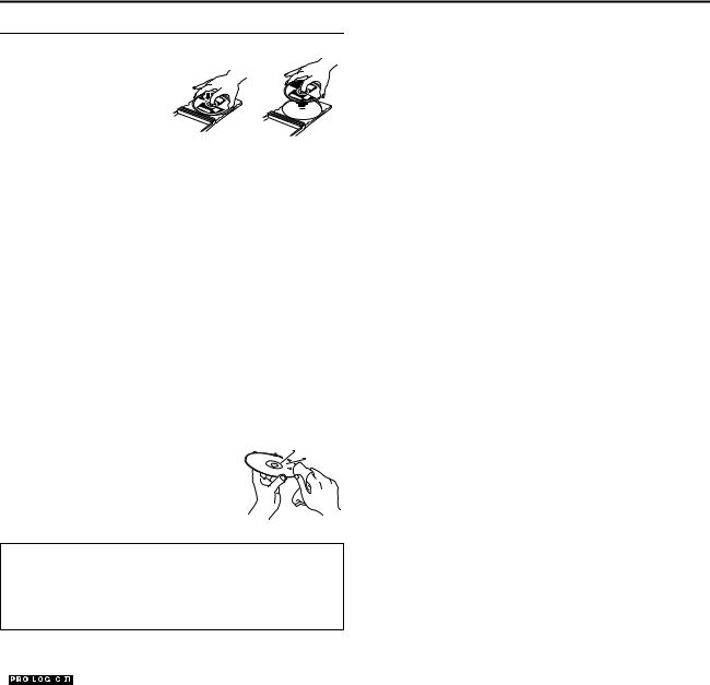
Care And Handling Of Discs
How to handle discs
When handling a disc, do not touch the surface of the disc.
Since discs are made of plastic, they are easily damaged. If a disc gets dirty, dusty, scratched or warped, the images and sound will not be
picked up correctly, and such a
disc may cause the unit to malfunction.
Label side:
Do not damage the label side, stick paper to or use any adhesives on its surface.
Recording side:
Make sure that discs are not scratched and dirty on the recording side before use. Scratches and dirt on the recording side of a disc may hinder proper playback and recording. Also be careful that a DVD-RAM disc may get scratched or dirty when removed from cartridge then put back in after use.
Storage
Make sure that discs are kept in their cases. If discs are piled on top of one another without their protective cases, they can be damaged. Do not put discs in a location where they may be exposed to direct sunlight, or in a place where the humidity or temperature is high. Avoid leaving discs in your car!
Maintenance of discs:
If there are fingerprints or other dirt adhering to a disc, wipe with a soft dry cloth, moving from the centre outwards.
If a disc is difficult to clean, wipe with a cloth moistened with water. Never use record cleaners, petrol, alcohol or any anti-static agents.
CAUTION:
Sometimes during playback, noise may appear or images may be garbled. This is sometimes due to the disc. (It may not be up to industry standards.)
These symptoms are caused by the discs, not by the malfunction of the unit.


 b
b
●Manufactured under licence from Dolby Laboratories. ADolbyB, APro LogicB and double-D symbol are trademarks of Dolby Laboratories.
●ADTSB and ADTS 96/24B are trademarks of Digital Theater Systems, Inc.
●SHOWVIEW is a trademark of Gemstar Development Corporation. The SHOWVIEW system is manufactured under license from Gemstar Development Corporation.
●This product incorporates copyright protection technology that is protected by method claims of certain U.S. patents and other intellectual property rights owned by Macrovision Corporation and other rights owners. Use of this copyright protection technology must be authorized by Macrovision Corporation, and is intended for home and other limited viewing users only unless otherwise authorized by Macrovision Corporation. Reverse engineering or disassembly is prohibited.
6
INDEX
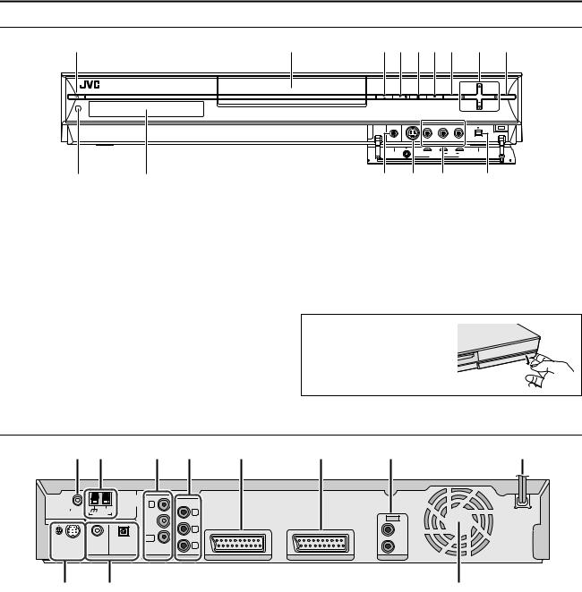
Front View
A B C D E F G H I
JK
AStandby/On Button (A)
BDisc tray
CEject Button (M) A pg. 5
DPlay Button (I) A pg. 25
EStop Button (o) A pg. 25
FRecord Button (R) A pg. 39
GEnter Button (ENTER) A pg. 28
HVolume Button (VOL +/–) A pg. 26 Selection Keys (FGDE) A pg. 28
IAudio Source Button (SOURCE) A pg. 44
NOTE:
The ENTER button (G) and selection keys (H) on the unit can only be used for ALocating A Desired Scene Using The DVD MenuB (A pg. 28).
ENTER |
VOL |
SOURCE |
PHONES |
S-VIDEO |
VIDEO L(MONO) |
AUDIO |
R |
DV IN |
|
|
INPUT F1 |
|
|
|
L M N O
JRemote Sensor A pg. 9
KFront Display Panel A pg. 8
LHeadphone Terminal [PHONES] A pg. 26
MS-video Input Connector [S-VIDEO] A pg. 67
NVideo/Audio Input Connectors [VIDEO/AUDIO (L(MONO)/ R)] A pg. 67
ODV Input connector [DV IN (A*)] A pg. 65
*A(i.Link) refers to the IEEE1394-1995 industry specification and extensions thereof. The Alogo is used for products compliant with the i.Link standard.
To access covered connectors, |
|
press lightly on the extreme right of |
|
PULL-OPEN then pull and open the |
|
cover slowly. |
PULL-OPEN |
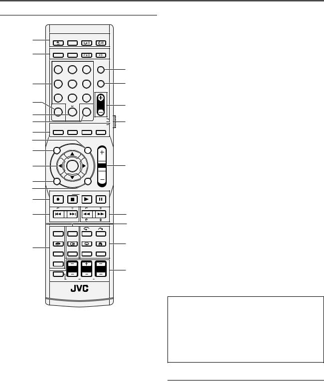
Rear View
|
A B |
C |
D |
E |
F |
G |
H |
|
|
|
|
FM/AM |
COMPONENT |
|
|
|
|
|
|
|
ANTENNA IN |
|
|
|
|
|
|
|
|
|
|
|
|
|
|
FM 75 |
COAXIAL |
AM EXT |
|
Y |
|
|
|
|
|
|
AM LOOP |
|
|
|
|
|
|
|
|
|
|
|
|
AUDIO |
|
|
|
|
|
|
|
|
|
|
|
|
|
|
|
PB |
|
|
LEFT |
|
|
|
|
OUT |
|
|
|
|
|
TO SP - PWR1 |
COAXIAL OPTICAL |
PR |
|
|
|
SP - PWR3 |
|
|
|
RIGHT |
|
|
L-1/L-2 DIGITAL INPUT |
TV ANTENNA VIDEO OUT |
L-1 INPUT / OUTPUT |
L-2 INPUT / DECODER |
OUTPUT |
I J
AFM Antenna Input Connector [FM 75 K COAXIAL] A pg. 12
BAM Antenna Input Connector [AM LOOP] A pg. 12
CVHF/UHF Antenna Input/Output Connectors [TV ANTENNA IN/OUT] A pg. 11
DComponent Video Output Connectors [COMPONENT VIDEO OUT (Y/PB/PR)] A pg. 11
EL-1 Input/Output Connectors [L-1 INPUT/OUTPUT] A pg. 11, 68, 69, 71
FL-2 Input/Decoder Connector [L-2 INPUT/DECODER] A pg. 68, 69, 71
GAudio Output Connector [AUDIO OUTPUT] A pg. 11
HAC Power Cord A pg. 16
ISubwoofer Connecting Terminal [TO SP-PWR1/SP-PWR3] A pg. 16
JDigital Audio Input Connectors [L-1/L-2 DIGITAL INPUT (COAXIAL/OPTICAL)] A pg. 16
K
KCooling Fan
●This prevents the temperature from rising inside the unit. Do not remove it.
●Install the unit so as not to block the area around the fan.
●The unit may become hot when it is turned off, as the cooling fan on the rear of the unit is not activated. However, the cooling fan may be activated in the following cases;
^In the Automatic Satellite Programme Recording standby mode (A pg. 54), slightly before the starting time of VPS/ PDC recording (A pg. 50).
^If you connect the decoder or satellite receiver to [L-2 INPUT/DECODER], and if AL-2 SELECTB is set to ADECODERB, ASAT VIDEO/RGBB or ASAT S-VIDEO/RGBB. (A pg. 70)
^When AJUST CLOCKB is set to AONB (A pg. 82)
(Set AJUST CLOCKB to AOFFB if you mind the noise of the fan.)
7
INDEX
Front Display Panel
|
|
A |
|
|
|
|
|
B C D |
E F |
|
G H I |
|
JKL |
|
|
M |
|
N |
O |
P |
|
Q |
||||||||||||||||||||||||||||||||
|
|
|
|
|
|
|
|
|
|
|
|
|
|
|
|
|
|
|
|
|
|
|
|
|
|
|
|
|
|
|
|
|
|
|
|
|
|
|
|
|
|
|
|
|
|
|
|
|||||||
|
|
|
|
|
|
|
|
|
|
|
|
|
|
|
|
|
|
|
|
|
|
|
|
|
|
|
|
|
|
|
|
|
|
|
|
|
|
|
|
|
|
|
|
|
|
|
|
|
|
|
|
|
|
|
|
|
|
TV DIRECT |
|
|
|
VPS/PDC |
|
DISC |
|
|
|
|
TUNED P ST |
RDS |
|
AUTO |
|
NEWS |
TA |
|
PRG |
|
1 |
|
kHz |
|
|||||||||||||||||||||||||||
|
|
|
|
|
|
|
|
|
||||||||||||||||||||||||||||||||||||||||||||||
|
|
|
L |
C |
|
R SW |
|
|
RESUME |
|
|
|
|
|
GRP |
|
TITLE |
|
TRK |
|
CHAP. |
|
MUTE |
|
|
|
INFO |
|
RND |
|
A-B |
|
MHz |
|
||||||||||||||||||||
|
|
|
|
|
|
|
|
|
|
|
|
|
|
|
|
|
|
|
VR DV |
|
|
|
|
|
|
|
|
|
|
|
|
|
|
|
|
|
|
|
|
|
|
|
|
|
|
|
|
|
|
|
|
|
||
|
|
|
LS |
S |
|
RS |
|
LFE |
|
|
|
|
|
|
|
|
|
|
|
|
|
|
|
|
|
|
|
|
|
|
|
|
|
|
|
|
|
|
|
|
|
|
|
|
|
|
||||||||
|
|
|
|
|
|
|
|
|
|
XP SP LP EP FR |
|
|
|
|
|
|
|
|
|
|
|
|
|
|
|
|
|
|
|
|
|
|
|
|
|
|
|
|
|
|
|
|
|
|||||||||||
|
|
|
|
|
|
|
|
|
|
|
|
|
|
|
|
|
|
|
|
|
|
|
|
|
|
|
|
|
|
|
|
|
|
|
|
|
|
|
|
|
|
|||||||||||||
|
|
|
|
|
D |
|
|
|
|
PL |
|
|
|
|
|
|
|
|
V CD |
|
|
|
|
|
|
|
|
|
|
|
|
|
|
|
|
|
|
|
|
|
|
|
|
|
|
|
|
|
|
|
|
|
||
|
|
|
|
|
|
|
|
|
|
|
|
|
|
|
|
|
|
|
|
|
|
|
|
|
|
|
|
|
|
|
|
|
|
|
|
|
|
|
|
|
|
|
|
|
|
|
|
|||||||
|
|
|
|
|
|
|
96/24 DSP |
|
|
|
|
DVD-R A M W |
|
|
|
|
|
|
|
|
|
|
|
|
|
|
CH |
|
|
|
|
|
|
|
|
|
|
|
|
|
||||||||||||||
|
|
|
|
|
|
|
|
|
|
|
|
|
|
|
|
|
|
|
|
|
|
|
|
|
|
|
|
|
|
|
|
|
|
|
|
|
|
|
|
|
|
|
|
|
|
|
|
|
|
|
|
|
|
|
|
|
|
|
|
|
|
|
|
|
|
|
|
|
|
|
|
|
|
|
|
|
|
|
|
|
|
|
|
|
|
|
|
|
|
|
|
|
|
|
|
|
|
|
|
|
|
|
|
|
|
|
|||
|
|
|
|
|
|
|
R |
|
|
|
|
|
S |
|
|
|
|
|
|
|
|
|
|
|
|
|
T U |
V |
|
|
|
|
|
|
|
|
|
|||||||||||||||||
A TV DIRECT Indicator A pg. 31 |
|
|
|
|
|
|
|
|
|
|
|
M AUTO MUTE Indicator A pg. 44 |
|
|
|
|
|
|
|
|
|
|||||||||||||||||||||||||||||||||
B Source signal indicators, etc. |
|
|
|
|
|
|
|
|
|
|
|
|
|
Lights when FM mode is in the auto muting mode. |
||||||||||||||||||||||||||||||||||||||||
Light to indicate the incoming signals. |
|
|
|
|
|
|
N Radio Data System Indicator A pg. 47 |
|
|
|
|
|
|
|||||||||||||||||||||||||||||||||||||||||
L |
: Lights when the left channel signal is detected. |
|
|
|
|
|
|
|
|
ARDSB |
: |
Lights when the RDS service of a FM station is |
||||||||||||||||||||||||||||||||||||||||||
C |
: Lights when the centre channel signal is detected. |
|
|
|
|
|
|
|
|
|
|
being received. |
|
|
|
|
|
|
|
|
|
|||||||||||||||||||||||||||||||||
R |
: Lights when the right channel signal is detected. |
|
|
|
|
ATAB |
|
|
|
: |
Traffic Announcement in your area. |
|||||||||||||||||||||||||||||||||||||||||||
LFE |
: Lights when the LFE channel signal is detected. |
|
|
|
|
|
|
|
ANEWSB : News. |
|
|
|
|
|
|
|
|
|
|
|
|
|
||||||||||||||||||||||||||||||||
LS |
: Lights when the left surround channel signal is detected. |
|
|
AINFOB |
: |
Programme the purpose of which is to impart |
||||||||||||||||||||||||||||||||||||||||||||||||
RS |
: Lights when the right surround channel signal is |
|
|
|
|
|
|
|
|
|
|
|
|
|
advice in the widest sense. |
|
|
|
|
|
|
|||||||||||||||||||||||||||||||||
|
|
detected. |
|
|
|
|
|
|
|
|
|
|
|
|
|
|
O PRG/RND Indicator A pg. 38 |
|
|
|
|
|
|
|
|
|
||||||||||||||||||||||||||||
S |
: Lights when the monaural surround channel signal or 2 |
|
|
APRGB |
: |
Lights when Programme Playback mode is set. |
||||||||||||||||||||||||||||||||||||||||||||||||
|
|
channel Dolby Surround signal is detected. |
|
|
|
|
|
|
|
|
ARNDB |
: |
Lights when Random Playback mode is set. |
|||||||||||||||||||||||||||||||||||||||||
ASWB : Always lights except during HEADPHONE and TV |
|
|
P Repeat Mode Indicator (x/1/A-B) A pg. 35, 36 |
|||||||||||||||||||||||||||||||||||||||||||||||||||
|
|
DIRECT mode. |
|
|
|
|
|
|
|
|
|
|
|
|
|
|
|
|
Select Repeat Playback mode on the on-screen bar. |
|||||||||||||||||||||||||||||||||||
The channel with A__B shows that the corresponding speakers |
|
|
AxB |
|
: Whole disc is played back repeatedly. |
|||||||||||||||||||||||||||||||||||||||||||||||||
are reproducing the channels’ sound. |
|
|
|
|
|
|
|
|
Ax 1B |
|
: A single title/chapter/track is played back |
|||||||||||||||||||||||||||||||||||||||||||
If the channels’ sound decoded into 5.1 channel is reproduced, |
|
|
|
|
|
|
|
|
|
repeatedly. |
|
|
|
|
|
|
|
|
|
|||||||||||||||||||||||||||||||||||
only A__B lights. |
|
|
|
|
|
|
|
|
|
|
|
|
|
|
|
|
Ax A-BB |
: The selected part (A-B) is played back |
||||||||||||||||||||||||||||||||||||
C RESUME Indicator A pg. 29 |
|
|
|
|
|
|
|
|
|
|
|
|
|
|
|
|
|
|
|
|
repeatedly. |
|
|
|
|
|
|
|
|
|
||||||||||||||||||||||||
Lights when resume is set. |
|
|
|
|
|
|
|
|
|
|
|
|
|
No display |
: Repeat Playback mode is off. |
|
|
|
|
|||||||||||||||||||||||||||||||||||
D VPS/PDC Indicator A pg. 50 |
|
|
|
|
|
|
|
|
|
|
|
Q Frequency Indicator A pg. 44 |
|
|
|
|
|
|
|
|
|
|||||||||||||||||||||||||||||||||
Lights when checking if the station being received transmits a |
|
|
|
|
AkHzB lights during AM reception. |
|
|
|
|
|
|
|
|
|
||||||||||||||||||||||||||||||||||||||||
VPS/PDC signal. |
|
|
|
|
|
|
|
|
|
|
|
|
|
|
|
|
AMHzB lights during FM reception. |
|
|
|
|
|
|
|
|
|
||||||||||||||||||||||||||||
E VR/DV Indicator A pg. 65 |
|
|
|
|
|
|
|
|
|
|
|
R Digital Sound Type/Dolby Surround and DSP mode |
||||||||||||||||||||||||||||||||||||||||||
AVRB : Lights when a DVD-RW disc formatted in VR mode is |
|
|
|
|
Indicators A pg. 42 |
|
|
|
|
|
|
|
|
|
||||||||||||||||||||||||||||||||||||||||
|
|
loaded. |
|
|
|
|
|
|
|
|
|
|
|
|
|
|
|
|
|
|
|
|
|
|
|
|
|
|
|
D |
|
: Lights when Dolby Digital sound is being played. |
||||||||||||||||||||||
ADVB : Lights when DV channel is being selected. |
|
|
|
|
|
|
|
|
|
|
|
|
|
|
: Lights when DTS sound is being played. |
|||||||||||||||||||||||||||||||||||||||
F DISC Timer Indicator A pg. 51 |
|
|
|
|
|
|
|
|
|
|
|
|
|
|
|
|
96/24 : Lights when DTS96/24 sound is being played. |
|||||||||||||||||||||||||||||||||||||
|
|
: Lights when a disc set up for On-Disc Timer |
|
|
|
|
|
|
|
|
|
|
PL II |
|
: Lights during Dolby Pro Logic II mode. |
|||||||||||||||||||||||||||||||||||||||
|
|
Programming is loaded. |
|
|
|
|
|
|
|
|
|
|
|
|
|
ADSPB |
|
: Lights during All Channel Stereo mode or DAP |
||||||||||||||||||||||||||||||||||||
|
|
: Lights when timer recording other than On-Disc Timer |
|
|
|
|
|
|
|
|
|
|
|
mode (A pg. 43). |
|
|
|
|
|
|
|
|
|
|||||||||||||||||||||||||||||||
|
|
Programming is on stand-by or being executed. |
|
|
|
|
|
|
S Disc Type Indicator |
|
|
|
|
|
|
|
|
|
||||||||||||||||||||||||||||||||||||
|
|
: Lights when On-Disc Timer Programming is on stand-by |
|
|
When a disc is loaded, the type of the disc (DVD-RAM, -R, -RW, |
|||||||||||||||||||||||||||||||||||||||||||||||||
|
|
or being executed. |
|
|
|
|
|
|
|
|
|
|
|
|
|
|
|
|
VCD, CD) is indicated. |
|
|
|
|
|
|
|
|
|
||||||||||||||||||||||||||
|
|
: Blinks quickly if you press TIMERj in the following |
|
|
|
|
Recording Mode Indicator (XP/SP/LP/EP/FR) A pg. 39 |
|||||||||||||||||||||||||||||||||||||||||||||||
|
|
cases; |
|
|
|
|
|
|
|
|
|
|
|
|
|
|
|
|
|
|
|
|
|
|
|
|
|
Disc Status Indicator A pg. 25, 39 |
|
|
|
|
|
|
||||||||||||||||||||
|
|
● Disc is not loaded. |
|
|
|
|
|
|
|
|
|
|
|
|
|
R: |
While recording |
|
|
|
|
|
|
|
|
|
|
|
|
|
||||||||||||||||||||||||
|
|
● Clock has not been set. |
|
|
|
|
|
|
|
|
|
|
|
|
|
I: |
During Playback |
|
|
|
|
|
|
|
|
|
|
|
|
|
||||||||||||||||||||||||
|
|
● There is no programme setting. |
|
|
|
|
|
|
|
|
W: While paused |
|
|
|
|
|
|
|
|
|
|
|
|
|
||||||||||||||||||||||||||||||
G Video Indicator (z) A pg. 25 |
|
|
|
|
|
|
|
|
|
|
|
T Automatic Satellite Programme Recording Indicator |
||||||||||||||||||||||||||||||||||||||||||
|
|
|
|
|
|
|
|
|
|
|
|
|
A pg. 54 |
|
|
|
|
|
|
|
|
|
|
|
|
|
|
|
|
|
|
|
||||||||||||||||||||||
Lights when video mode is selected by pressing TV/VIDEO. |
|
|
|
|
|
|
|
|
|
|
|
|
|
|
|
|
|
|
|
|
|
|
|
|||||||||||||||||||||||||||||||
|
|
|
|
Lights when the unit is in the Auto Satellite Programme |
||||||||||||||||||||||||||||||||||||||||||||||||||
H GRP/TITLE Indicator |
|
|
|
|
|
|
|
|
|
|
|
|
|
|
|
|
||||||||||||||||||||||||||||||||||||||
|
|
|
|
|
|
|
|
|
|
|
|
|
|
|
|
Recording standby mode. |
|
|
|
|
|
|
|
|
|
|||||||||||||||||||||||||||||
Indicates the group (GRP) and title (TITLE) being played back. |
|
|
|
|
|
|
|
|
|
|
|
|||||||||||||||||||||||||||||||||||||||||||
U Multi Display |
|
|
|
|
|
|
|
|
|
|
|
|
|
|||||||||||||||||||||||||||||||||||||||||
The number being played back is displayed on the Multi Display. |
|
|
|
|
|
|
|
|
|
|
|
|
|
|||||||||||||||||||||||||||||||||||||||||
|
|
Displays clock, received channel, elapsed time, remaining time, |
||||||||||||||||||||||||||||||||||||||||||||||||||||
I TUNED Indicator A pg. 44 |
|
|
|
|
|
|
|
|
|
|
|
|
|
|||||||||||||||||||||||||||||||||||||||||
|
|
|
|
|
|
|
|
|
|
|
|
|
GRP, TITLE, TRK, CHAP etc. |
|
|
|
|
|
|
|
|
|
||||||||||||||||||||||||||||||||
Lights when a radio station with sufficient signal strength is tuned. |
|
|
|
|
|
|
|
|
|
|
|
|||||||||||||||||||||||||||||||||||||||||||
|
|
Also displays status of the unit. |
|
|
|
|
|
|
|
|
|
|||||||||||||||||||||||||||||||||||||||||||
J Video Output Indicator (q) A pg. 77 |
|
|
|
|
|
|
|
|
|
|
|
|
|
|
|
|
|
|||||||||||||||||||||||||||||||||||||
|
|
|
|
|
|
V Remaining Time/Elapsed Time Display A pg. 30, 40 |
||||||||||||||||||||||||||||||||||||||||||||||||
No display: Indicates that interlace mode is engaged. |
|
|
|
|
|
|
||||||||||||||||||||||||||||||||||||||||||||||||
|
|
|
|
|
|
|
|
Lights when remaining time of DVD-RAM, DVD-R and DVD-RW |
||||||||||||||||||||||||||||||||||||||||||||||
q: |
|
|
|
Indicates that progressive mode is engaged. |
|
|
|
|
||||||||||||||||||||||||||||||||||||||||||||||
|
|
|
|
|
|
|
|
|
|
|
|
|
|
|
|
|
|
|
|
|
|
|
|
|
|
|
|
|
|
|
||||||||||||||||||||||||
(Example) q lights when video output mode is in progressive |
discs is displayed, and lights out when elapsed time is |
|
displayed. |
||
mode. |
||
No display: Indicates elapsed time of the disc. |
||
K ST Indicator A pg. 44 |
||
Displayed: Indicates remaining time of the disc. |
||
Lights during FM STEREO reception. |
||
|
LTRK/CHAP. Indicator
Indicates the track (TRK) and chapter (CHAP) being played back. The number being played back is displayed on the Multi Display.
8
INDEX
Remote Control
A |
OPEN/ |
|
TV |
AUDIO |
|
CLOSE TV/VIDEO |
|
||||
|
|
||||
B |
DVD |
FM/AM |
SAT |
TIMER |
|
|
|
|
|
|
|
|
|
ABC |
DEF |
TV DIRECT |
|
|
1 |
2 |
3 |
|
P |
|
GHI |
JKL |
MNO |
PROG |
|
C |
4 |
5 |
6 |
|
Q |
|
PQRS |
TUV |
WXYZ |
|
|
D |
7 |
8 |
9 |
|
|
CANCEL |
|
MEMORY |
PR |
R |
|
|
|
||||
E |
|
0 |
|
|
|
|
AUX |
MARK |
AUDIO |
|
|
F |
|
S |
|||
|
|
|
TV |
||
|
SHOWVIEW/ |
|
|
SAT |
|
G |
VIDEO Plus+ |
SATj |
SETTING SURROUND |
|
|
|
|
|
|
|
|
H |
TOP MENU |
|
NAVIGATION |
|
|
I |
|
PTY SEARCH |
|
||
|
|
|
|
|
|
J |
|
ENTER |
|
VOL |
T |
K |
|
|
|
|
|
L |
MENU |
|
RETURN |
|
|
|
STOP/CLEAR |
RDS DISPLAY |
|
||
|
REC |
PLAY |
PAUSE |
|
|
M |
|
|
|
|
|
|
|
TA/NEWS/INFO |
|
|
|
|
TUNING |
SLOW |
|
||
N |
|
|
|
|
U |
|
|
|
PTY |
|
V |
|
|
|
|
|
|
|
DISPLAY ON SCREEN |
|
|
||
|
REC MODE/ |
|
ANGLE/ |
|
|
|
REMAIN |
AUDIO |
SUBTITLE LIVE CHECK |
W |
|
O |
|
|
PROGRESSIVE |
|
|
FM MODE TEST TONE |
SET UP |
|
|||
SCAN |
|
||||
|
SMART |
|
|
|
|
|
S.SET UP |
|
|
|
|
L |
CENTER |
R |
X |
|
|||
SHIFT |
|
|
|
SURR. L |
S. WFR |
SURR. R |
|
AOpen/Close Button (M) A pg. 5 TV/VIDEO Button (TV/VIDEO) A pg. 25
TV STANDBY/ON Button (TV A) A pg. 72
AUDIO STANDBY/ON Button (AUDIO A) A pg. 17, 53
BDVD Button (DVD) A pg. 20
FM/AM Button (FM/AM) A pg. 44, 45
SAT STANDBY/ON Button (SAT A) A pg. 73 Timer Button (TIMERj) A pg. 49, 53
CNumber Keys A pg. 28, 37, 38, 58
DCancel Button (CANCEL) A pg. 37, 53, 80
EAuxiliary Button (AUX)
FMemory Button (MEMORY) A pg. 44, 56 Mark Button (MARK) A pg. 30
GSHOWVIEW/VIDEO Plus+ Button (SHOWVIEW/VIDEO Plus+) A pg. 49
Automatic Satellite Programme Recording Button (SATj) A pg. 53, 54
Setting Button (SETTING) A pg. 23
Surround Button (SURROUND) A pg. 26, 27, 43
HNavigation Button (NAVIGATION) A pg. 33, 55 Programme Type Search Button (PTY SEARCH) A pg. 46
ITop Menu Button (TOP MENU) A pg. 28
JSelection Keys (FGDE) A pg. 20 Enter Button (ENTER) A pg. 20
KMenu Button (MENU) A pg. 28
LReturn Button (RETURN) A pg. 49, 80
RDS Display Button (RDS DISPLAY) A pg. 45
MRecord Button (R) A pg. 39, 40 Stop Button (o) A pg. 25
Clear Button (CLEAR) A pg. 37, 53, 56 Play Button (I) A pg. 25
TA/NEWS/INFO Select Button (TA/NEWS/INFO) A pg. 47 Pause Button (W) A pg. 25
NTuning Buttons (TUNING +/–) A pg. 44 Reverse Skip Button (S) A pg. 28, 31, 34, 38 Forward Skip Button (T) A pg. 28, 31, 34, 38
ODisplay Button (DISPLAY) A pg. 30, 50 Recording Mode Button (REC MODE) A pg. 39
Remain Button (REMAIN ) A pg. 30 FM Mode Button (FM MODE) A pg. 44
Smart Surround Set Up Button (SMART S.SET UP) A pg. 22
PTV Direct Button (TV DIRECT) A pg. 31
QProgramme Button (PROG) A pg. 50
RProgramme Up/down Buttons (PR +/–) A pg. 39, 44
SRemote Control Selector Switch (AUDIO/TV/SAT) A pg. 72
TVolume Buttons (VOL +/–) A pg. 26, 72
UReverse Search Button (O) A pg. 28, 34 Reverse Slow Button (SLOW –) A pg. 29 Forward Search Button (N) A pg. 28, 34 Forward Slow Button (SLOW +) A pg. 29 Programme Type+ Button (PTY +) A pg. 46 Programme TypeButton (PTY –) A pg. 46
VOn-Screen Button (ON SCREEN) A pg. 10, 35
Audio Button (AUDIO
 ) A pg. 31 Test Tone Button (TEST TONE) A pg. 85
WOne Touch Replay Button (w) A pg. 29, 33 Skip Search Button (v) A pg. 29
Subtitle Button (SUBTITLE h) A pg. 30 Angle Button (ANGLE y) A pg. 30
Live Check Button (LIVE CHECK y) A pg. 34 Progressive Scan Button (PROGRESSIVE SCAN) A pg. 77 Set Up Button (SET UP) A pg. 20
XShift Button (SHIFT) A pg. 26 Left Buttons (L +/–) A pg. 26
Centre Buttons (CENTER +/–) A pg. 26 Right Buttons (R +/–) A pg. 26
Left Surround Buttons (SURR. L +/–) A pg. 26 Subwoofer Buttons (S. WFR +/–) A pg. 26 Right Surround Buttons (SURR. R +/–) A pg. 26
How To Use
Before use, insert two R03 size batteries into the remote control with the polarity (F and G) matched correctly as indicated on the battery compartment or on the lid.
●Point the remote control toward the receiving window.
●The maximum operating distance of the remote control is about 8 m.
NOTE:
If the remote control doesn’t work properly, remove its batteries, wait a short time, replace the batteries and then try again.
Operating The System From the Remote Control
Aim the remote control directly at the front panel of the centre unit. ● Do not block the remote sensor.
9
INDEX
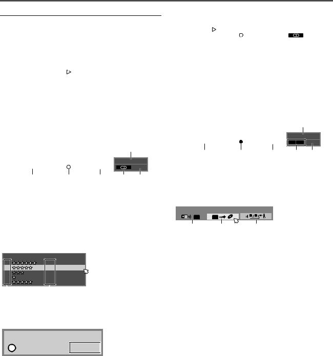
On-Screen Display
When ON SCREEN on the remote control is pressed, various operational indicators appear on the TV screen. To clear the operational indicators, press ON SCREEN twice.
When playing back a recorded title
A B C D E
|
|
|
|
|
|
|
|
|
|
|
DVD-VIDEO |
|
LPCM |
|
2ch |
|
|
|
|
|
|
|
|
|
TITLE1 CHAPTER1 |
|||||||
|
|
|
|
|
|
|
|
|
EACH 0:01:08 |
|
|
|
|
|
|
|
|
|
|
|
|
|
|
F |
|
|
|
G |
||||
ADisc type
BAudio mode
CCurrent status (playback)
DPlayback title number
EPlayback chapter number
FCurrent playback point
GElapsed playing time
When recording
A B
|
|
|
|
|
|
|
DVD-RW/VR |
|
|
|
TITLE14 CHAPTER1 |
||
|
SP |
|||||
|
|
|
|
|
|
EACH 0:01:23 |
|
|
|
|
|
|
|
D E F
ADisc type
BRecording mode
CCurrent time
DRecording point
ECurrent status (recording)
FElapsed recording time
GAudio mode
HRecording channel number
When pressing REC MODE:
(Appears for eight seconds.)
REC QUALITY |
RECORDABLE TIME |
XP: |
1:00 |
SP: |
2:00 |
LP : |
4:01 |
EP: |
6:03 |
FR: |
2:31 (FR150) |
C
6:04PM
PR 95
G H
A B
ARecording mode
BRemaining disc time for each recording speed
During Instant Timer Recording (ITR)
SP TITLE13 CHAPTER1
ITR 0:13 A
A
A Record remaining time
When using Live Memory playback |
|
|
|
|
|
|
|||||||||||
|
A |
|
|
|
|
|
|
|
|
B |
|||||||
|
|
|
|
|
|
|
|
|
|
|
|
|
|
|
|
|
|
|
DVD |
|
|
|
|
|
|
|
|
|
|
|
|
|
|
|
|
|
-RAM |
TITLE2 |
0:12:27 |
LP |
TITLE2 CHAPTER1 |
|
|
6:36PM |
|||||||||
|
|
|
|
|
|
|
|
|
|
EACH 0:13:34 |
|
|
|
PR |
|
10 |
|
|
|
|
|
|
|
|
|
|
|
|
|
|
|||||
|
|
|
|
|
|
|
|
|
|
|
|
|
|
|
|
|
|
|
|
|
|
C |
|
D |
|
E |
|
F G |
|||||||
ADisc type
BCurrent time
CBar meter for recording/playback
DRecording mode
ECurrent playback time/Elapsed recording time
FAudio mode
GRecording channel number
DV Dubbing
When capturing images from the external DV equipment
A B
|
|
|
|
|
|
DVD-RW/VR |
|
SP |
TITLE12 CHAPTER-- |
||
|
|
|
|
|
EACH 0:00:00 |
|
|
|
|
|
|
C D E
ADisc type
BCurrent time
CCurrent recording point
DCurrent status (recording)
EElapsed recording time
FSound mode
GRecording channel (DV input)
DV DUBBING |
|
AUDIO 1 |
DV |
DV |
1 |
2 |
|
|
||
A |
|
B |
C |
--:--
L R DV
F G
ADisplays when remote control is set to DV control mode.
BAuto capture button
CSound monitor switch
10
INSTALLING YOUR NEW UNIT

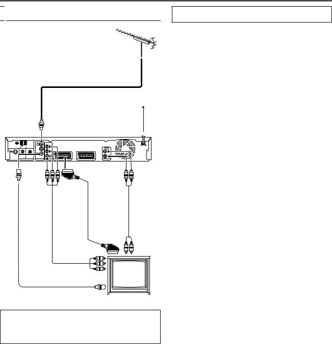
 Connecting The TV And TV Antenna
TV aerial cable
Mains outlet
Mains power cord
Back of unit |
To [TV ANTENNA IN] |
|
||
|
|
|
|
|
IN |
|
|
|
|
|
|
|
LEFT |
|
OUT |
|
|
|
|
|
|
|
RIGHT |
|
|
|
To [L-1 INPUT/ |
To [AUDIO |
|
|
|
OUTPUT] |
||
|
|
|
|
OUTPUT] |
To [TV |
To |
|
|
|
ANTENNA |
[COMPONENT |
|
|
|
OUT] |
VIDEO OUT |
21-pin SCART |
|
|
|
(Y/PB/PR)] |
|
Audio |
|
|
|
cable |
||
|
|
|
(supplied) |
cable |
|
|
|
|
(not |
|
|
|
|
supplied) |
|
Component |
|
video cable |
RF cable |
(not supplied) |
|
|
(supplied) |
|
|
TV |
|
To 75 ohm terminal |
It’s essential that your unit be properly connected.
ATTENTION:
●Your TV must have a 21-pin AV input connector (SCART) for the basic connection to the unit.
●Connect the AC plug only after all connections to the TV has been completed.
THESE STEPS MUST BE COMPLETED BEFORE ANY VIDEO OPERATION CAN BE PERFORMED.
1Make sure the package contains all of the accessories listed in AACCESSORIESB (A pg. 92).
2Place the unit on a stable, horizontal surface.
3Connect the unit to a TV depending on the TV and cables you use.
8 Basic Connection
To connect to a TV with 21-pin SCART input connector ^
ADisconnect the TV aerial cable from the TV.
BConnect the TV aerial cable to the [TV ANTENNA IN] connector on the rear panel of the unit.
CConnect the [TV ANTENNA OUT] connector on the rear panel of the unit and the TV’s aerial connector with the supplied RF cable.
DConnect the [L-1 INPUT/OUTPUT] connector on the rear panel of the unit and the TV’s 21-pin SCART connector with a supplied 21-pin SCART cable.
●The [L-1 INPUT/OUTPUT] connector accepts and delivers either a composite signal (regular video signal), Y/C signal or RGB signal.
●Set your TV to the VIDEO, Y/C, or RGB mode according to the type of your TV’s SCART connector.
8 Component Video Connection
To connect to TV’s component video input connectors ^
APerform steps A - C of ABasic ConnectionB.
BConnect the unit’s [COMPONENT VIDEO OUT (Y/PB/PR)] connectors to the TV’s component video input connectors.
CConnect the unit’s [AUDIO OUTPUT] connectors to the TV’s AUDIO input connectors.
●You can obtain high-quality component video pictures.
●By using the component video connection, you can view the images in the progressive mode. For switching to the progressive mode, refer to AScan Mode SetB (A pg. 77).
NOTES:
●Select an appropriate option of AL-1 OUTPUTB as follows (A pg. 69):
When your TV’s SCART |
Set AL-1 OUTPUTB to: |
|
connector accepts: |
||
|
||
|
|
|
Composite signals |
ASCART VIDEOB |
|
|
|
|
Y/C signal (separated |
|
|
luminance (brightness) and |
ASCART S-VIDEOB |
|
chrominance (colour) signals) |
|
|
|
|
|
RGB signal |
ASCART RGBB |
|
|
|
|
Component video signal |
ACOMPONENTB |
|
|
|
When the setting selected is not in accordance with the TV connected and depending on the type of appliance connected to the unit, the correct picture will not appear.
●If you possess a satellite receiver, refer to AConnecting To A Satellite ReceiverB as well. (A pg. 71)
●Connecting the FM and AM antennas (A pg. 12)
●Connecting the satellite speakers (A pg. 14)
●Connecting the powered subwoofer (A pg. 16)
●Connecting the power cord (A pg. 16)
11
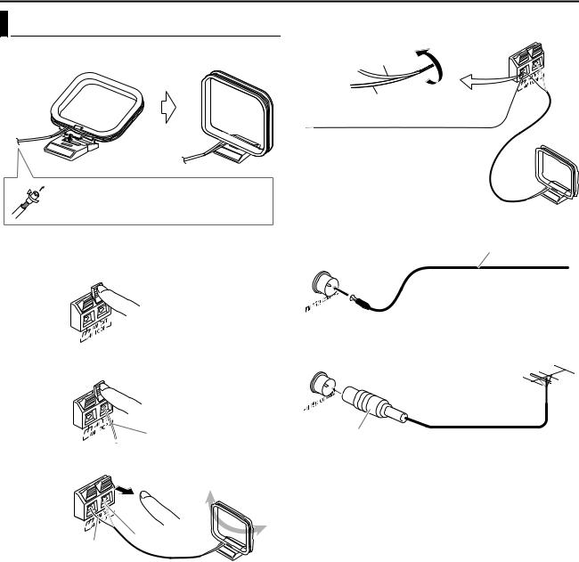
|
INSTALLING YOUR NEW UNIT |
Connecting The FM And AM Antennas |
If reception is poor |
Centre unit |
|
8 AM loop antenna |
AM loop antenna |
Setting up supplied AM loop antenna |
If the antenna cord is covered with the insulation coat, twist and pull off the insulation coat to remove.
Connecting AM loop antenna
1
Centre unit
2
Antenna cord
3
White
Black
●Turn the loop antenna until you have the best reception during AM reception.
NOTE:
Make sure the antenna conductors do not touch any other terminals, connecting cords and power cords. This could cause poor reception.
Outdoor single vinyl-covered wire antenna (not supplied)
8 FM antenna
FM antenna (supplied)
Centre unit
Extend the supplied FM antenna horizontally.
If reception is poor
Centre unit
Outdoor FM antenna (not supplied)
Standard type (75 K coaxial) connector
NOTE:
We recommend that you use coaxial cable for the FM antenna as it is well-shielded against interference.
12
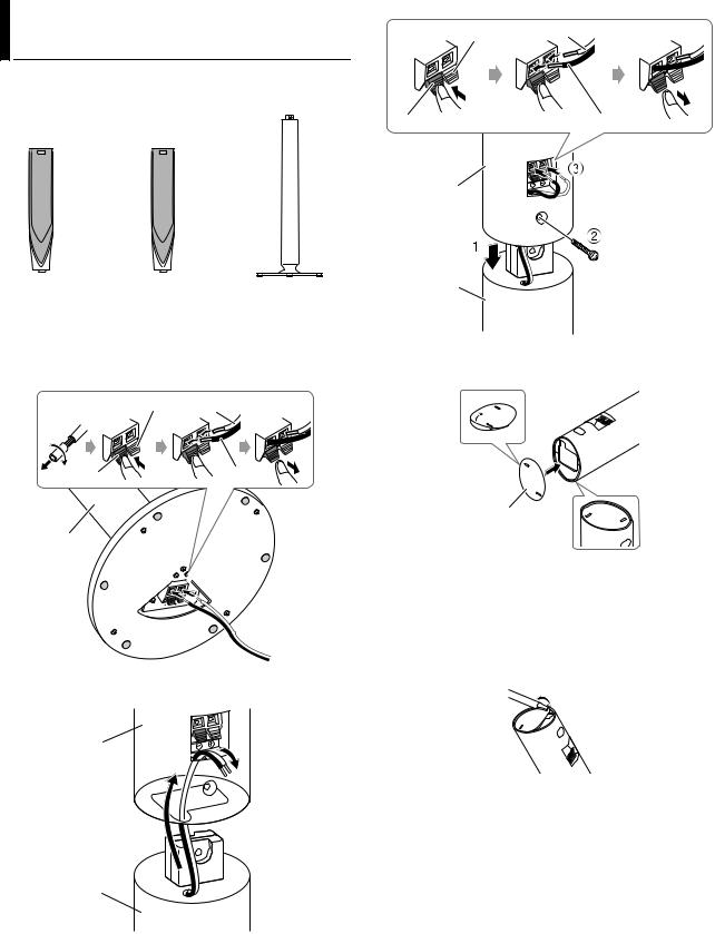
INSTALLING YOUR NEW UNIT |
This page is for TH-R3 |
Assembling The Front And Surround
Speakers
The following procedure explains the front speaker assembly. The assembly of both the front and surround speakers are done in the same manner.
Front speaker |
Surround speaker |
Stand (x4) |
(x2) |
(x2) |
|
Before assembling^
●Prepare a Phillips screwdriver (not supplied).
●Take care not to drop any component part while assembling; otherwise, it may cause damage to the floor or injury.
1
Red White
Black |
Black |
Stand
2
Speaker
Stand
3
Red White
Black |
Black |
Speaker
Stand |
Screw (supplied) |
|
When installing the front and surround speakers on the wall;
●Attach the supplied bottom cover on the bottom of each speakers as illustrated.
Bottom cover
●Be sure to have them installed on the wall by a qualified personnel.
●DO NOT install the satellite speakers on the wall by yourself to avoid unexpected damage from their falling off the wall due to incorrect installation or weakness in wall structure.
●Care must be taken in selecting a location for speaker installation on a wall. Injury to personnel or damage to equipment may result if the speakers installed interfere with daily activities.
●If attaching the stand to the speaker, remove the bottom cover by inserting a flat-pointed tool into the hole of the bottom cover.
13
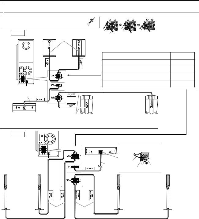
INSTALLING YOUR NEW UNIT

 Connecting The Satellite (Front, Centre, Surround) Speakers
Before connecting the speaker cords;
Twist and pull the insulation coat off and remove.
TH-R1 |
Speaker cord |
|
|
|
4 m |
|
|
|
|
|
|
|
|
● Connect the black cords to the black (G) terminals. |
|
|
|
● Connect the white cords to the (F) terminals |
|
|
|
referring to the table below: |
|
|
Front speakers |
FRONT SPEAKERS (LEFT) |
White |
|
FRONT SPEAKERS (RIGHT) |
Red |
|
|
SP-THS55F |
||
|
|
CENTRE SPEAKER |
Green |
4 |
16 |
SURROUND SPEAKERS (LEFT) |
Blue |
|
|
||
|
|
SURROUND SPEAKERS (RIGHT) |
Grey |
Powered subwoofer SP-PWR1 |
|
|
|
|
4 m |
|
|
|
|
Surround speakers |
|
|
|
SP-THS55S |
|
Centre speaker SP-THS55C |
10 m |
The satellite speakers are equipped with their speaker cords attached directly to their speaker unit instead of having speaker terminals on their cabinet.
TH-R3 |
|
|
|
|
|
|
Centre speaker |
Powered subwoofer |
4 |
16 |
SP-THS66C |
|
|
White |
|
SP-PWR3 |
|
|
|
|
|
|
Black |
|
|
|
4 m |
|
|
|
Red |
|
|
|
Black |
Front speakers |
Surround speakers |
|
SP-THS66S |
||
SP-THS66F |
||
|
4 m |
10 m |
CAUTIONS:
●When you connect speakers other than the supplied ones, use speakers of the same speaker impedance (SPEAKER IMPEDANCE) indicated near the speaker terminals on the rear of the powered subwoofer.
●DO NOT connect more than one speaker to one speaker terminal.
Precautions for daily use
●When moving the speakers, do not pull the speaker cords; otherwise, the speakers may fall over, causing damage or injury.
●Do not reproduce sounds at so high a volume that they are distorted; otherwise, the speakers may be damaged by internal heat build-up.
●When holding a speaker, always grasp the lower portion. (TH-R3)
●Do not lean against the speakers, as the speakers could fall down or break, possibly causing an injury. Especially make sure that children do not lean against them. (TH-R3)
14
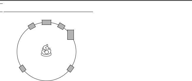
INSTALLING YOUR NEW UNIT

 Speaker Layout
Front left |
Centre speaker |
Front right speaker |
|
speaker |
|
|
Powered |
|
subwoofer |
Left surround |
Right surround |
speaker |
speaker |
●Place the satellite speakers on a flat and level surface.
●The front and centre speakers are magnetically shielded to avoid
colour distortions on TVs. However, if not installed properly, they may cause colour distortions. So, pay attention to the following when installing the speakers.
^When placing the speakers near a TV set, turn off the TV’s main power switch or unplug it before installing the speakers. Then wait at least 30 minutes before turning on the TV’s main power switch again.
Some TV’s may still be affected even though you have followed the above. If this happens, move the speakers away from the TV.
●The surround speakers are not magnetically shielded.
If it is located near the TV or monitor, it will probably cause colour distortion on the screen. To avoid this, do not place the speaker near the TV or monitor.
●Be sure to place the powered subwoofer to the TV’s right. If you place the powered subwoofer to the TV’s left, keep sufficient distance between them to prevent the TV screen from appearing mottled.
●When installing the satellite speakers on the wall;
^Be sure to have them installed on the wall by a qualified personnel.
DO NOT install the satellite speakers on the wall by yourself to avoid unexpected damage from their falling off the wall due to incorrect installation or weakness in wall structure.
^Care must be taken in selecting a location for speaker installation on a wall. Injury to personnel or damage to equipment may result if the speakers installed interfere with daily activities.
15
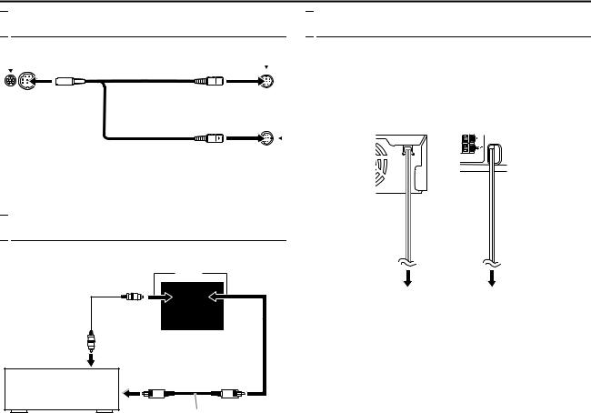
INSTALLING YOUR NEW UNIT

 Connecting The Powered Subwoofer
Centre unit |
Powered subwoofer |
|
System cord |
|
(supplied) |
Align the J marks. |
OR |
|
|
|
Align the J marks. |
NOTE:
The way of connecting the system cord varies depending on the type of the powered subwoofer.

 Connecting To A Digital Component
You can enjoy the sound of a digital component.
|
OR |
|
Digital coaxial |
COAXIAL OPTICAL |
|
cord (not supplied) |
||
|
||
|
L-1/L-2 DIGITAL INPUT |
|
To digital coaxial |
Centre unit |
|
|
||
output |
|
|
Satellite receiver |
To digital optical output |
|
|
||
|
Digital optical cord (not supplied) |
NOTE:
When connecting a video component such as a satellite receiver, operate this system to listen to the sound.

 Connecting The Power Cord
Connect the AC plug only after all connections have been completed.
●APLEASE WAITB blinks on the front display panel when the AC plug of the centre unit is connected into a mains outlet. And it takes approximately 30 seconds for the unit to be turned on. This is not a malfunction.
Centre unit |
Powered |
|
subwoofer |
Power cord |
Power cord |
Plug into AC outlets.
ATTENTION:
●Disconnect the power cord before cleaning or moving the system.
●Do not pull on the power cord to unplug the cord. When unplugging the cord, always grasp and pull the plug so as not to damage the cord.
16
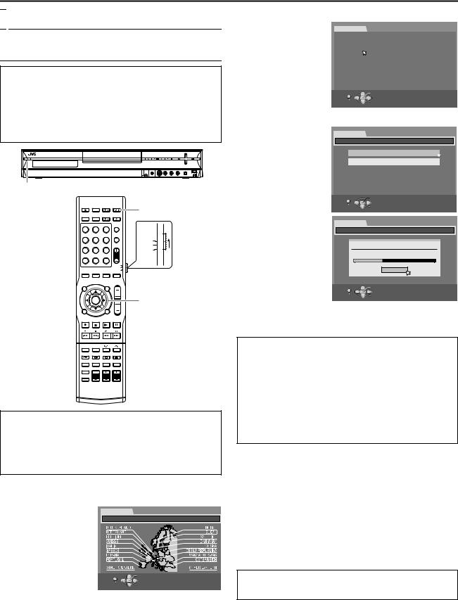
INITIAL SETTINGS

 Auto Set Up
Auto Channel Set/Auto Clock Set/Auto Guide
Programme Number Set
After the A button on the unit (or AUDIO A on the remote control) is pressed for the first time to turn on the unit, by simply selecting your country*, the Auto Set Up function sets the tuner channels, clock** and Guide Programme numbers automatically.
*If you live in Belgium (BELGIUM) or Switzerland (SUISSE), you also need to select your language.
**If you live in Hungary (MAGYARORSZÁG), Czech Republic (ČESKÁ REPUBLIKA), Poland (POLSKA) or other countries in Eastern Europe (OTHER EASTERN), set the clock manually.
1
|
|
|
AUDIO A |
1 |
2 |
3 |
|
4 |
5 |
6 |
AUDIO |
|
|
|
TV |
7 |
8 |
9 |
SAT |
|
0 |
|
|
|
|
VOL |
Selection Keys |
(FGDE)
ENTER
Before starting, make sure of the following:
●The TV aerial cable should be connected to the unit.
●The unit’s mains power cord should be connected to a mains outlet.
●Turn on the TV and select an input mode such as EXT1.
●Set the remote control selector switch to AUDIO.
●Press DVD on the remote control.
1Press A on the unit or AUDIO A on the remote control to turn on the unit. The Country Set display appears on the TV screen.
2 Press selection keys |
INITIAL SET UP |
|
|
|
to select your country’s |
INITIAL SET UP / COUNTRY SET |
|
||
name, then press |
|
|
|
|
ENTER. |
|
|
|
|
NOTES: |
|
|
|
|
● If you have selected |
|
|
|
|
ABELGIUMB or ASUISSEB, |
|
|
|
|
go to step 3. |
SET UP |
OK |
SELECT WITH [CURSORS] |
|
● If you have selected |
||||
|
SELECT |
THEN PRESS [ENTER] |
||
AMAGYARORSZÁGB, |
EXIT |
|||
|
||||
|
|
|
||
AČESKÁ REPUBLIKAB,
APOLSKAB or AOTHER EASTERNB, press ENTER, the Clock Set screen appears. Set the clock manually (A pg. 82), then go to step 4.
● If you have selected any other country name, go to step 4.
3 Press selection keys to
select the language of |
|
INITIAL SET UP |
|
|
|
|
|
|
|
your choice, then press |
|
INITIAL SET UP / LANGUAGE SET |
|
|
|
|
|
||
|
|
|
|
|
|
|
|
|
|
ENTER. The AUTO |
|
|
|
|
|
|
|
|
|
|
ENGLISH |
|
DEUTSCH |
|
FRANCAIS |
|
ITALIANO |
|
|
SET/T-V LINK display |
|
|
|
|
|
|
|
|
|
|
ESPAÑOL |
|
NEDERLANDS |
|
SVENSKA |
|
NORSK |
|
|
appears on the TV |
|
|
|
|
|
|
|
|
|
screen. |
|
SUOMI |
|
DANSK |
|
|
|
|
|
|
|
|
|
|
|
|
|
|
|
4Press selection keys to select AAUTO SETB, then press ENTER.
●Auto Channel Set is performed.
●When Auto Channel Set is completed, ASCAN COMPLETEDB appears on the TV screen.
ATTENTION:
SET UP |
OK |
RETURN SELECT
INITIAL SET UP
INITIAL SET UP / CHANNEL SET
AUTO SET
T-V LINK
 OK
OK
AAUTOB blinks on the front display panel; do NOT
press any button on the unit or remote control until the
front display panel shows clock time, APR1B or AcB as illustrated on page 19.
● When you have connected the unit to a TV
offering T-V Link via a fully-wired 21-pin SCART
cable (A pg. 11) and the TV is turned on, the unit automatically performs the Preset Download (A pg. 18) even if you select AAUTO SETB for Auto Set Up function.
ATTENTION:
Once you have performed AAuto Set UpB, even if the unit’s memory backup has expired, all the stored stations and their Guide Programme numbers remain in the unit’s memory and the unit will not perform AAuto Set UpB again. Perform clock set manually after turning on the unit. (A pg. 82)
If you have moved to a different area, perform each setting as required.
●TV Tuner setting (A pg. 79)
●Clock setting (A pg. 82)
If a new station starts broadcasting in your area, perform TV tuner setting. (A pg. 79)
NOTES:
●In areas where no TV station transmits a PDC (Programme Delivery Control) (A pg. 50) signal, the unit can perform neither Auto Clock Set nor Auto Guide Programme Number Set.
●If there is a power cut, or if you press A or SET UP while AAuto Set UpB is in progress, AAuto Set UpB will be interrupted. Be sure to turn off the unit power once and try again from step 1.
●Auto Clock Set may not function properly depending on the reception condition.
●If no sound accompanies the picture or the audio sounds unnatural on some channels that have been stored by AAuto Set UpB, the TV system setting for those channels may be incorrect. Select the appropriate TV system for those channels. (A pg. 80,
AINFORMATIONB)
After AAuto Set UpB is completed, perform AMonitor SetB
(A pg. 21). If you need to set the language, refer to ALanguageB on page 20 before proceeding to perform AMonitor SetB.
17
INITIAL SETTINGS

 Preset Download
Auto Channel Set by Downloading from TV/Auto Clock Set/Auto Guide Programme Number Set
ATTENTION:
You can use this function only with a TV offering T-V Link, etc.* Be sure to use a fully-wired 21-pin SCART cable.
*Compatible with TVs offering T-V Link, EasyLink, Megalogic, SMARTLINK, Q-Link or DATA LOGIC via a fully-wired 21-pin SCART cable. The degree of compatibility and available functions may differ by system.
 AUDIO A
1 2 3
4 5 6
7 8 9
PR +/-
0
VOL |
Selection Keys |
|
(FGDE) |
|
ENTER |
If you have connected the unit to your TV via a 21-pin SCART cable (A pg. 11), the unit will automatically perform Preset Download instead of the AAuto Set UpB in step 4 on page 17. After downloading, the unit sets the clock and Guide Programme numbers automatically.
●Perform steps 1 to 3 of AAuto Set UpB (A pg. 17) before continuing.
1Press selection keys to select AT-V LINKB, then press ENTER for confirmation.
●T-V LINK setting is
performed.
● When T-V LINK
setting is completed, |
AUTO SET |
|
|
|
ASCAN |
T-V LINK |
|
|
|
COMPLETEDB |
|
|
|
|
appears on the TV |
|
|
|
|
screen for about 5 |
|
|
|
|
seconds, then the |
SET UP |
OK |
SELECT WITH [CURSORS] |
|
normal screen |
||||
RETURN |
SELECT |
THEN PRESS [ENTER] |
||
resumes. |
|
|||
|
|
|
|
|
PLEASE WAIT... |
|
SET UP |
OK |
|
SELECT WITH [CURSORS] |
RETURN |
SELECT |
THEN PRESS [ENTER] |
|
|
|||
ATTENTION:
Preset positions on the front display panel increase from APR1B…APR3B…; do NOT press any button on the unit or remote control until the front display panel shows clock time, APR1B or A- - : - -B as illustrated on page 19.
●If you press any button on the unit or remote control while downloading is in progress, it will be interrupted.
NOTES:
●For details, refer to the instruction manual of your TV.
●In areas where no TV station transmits a PDC (Programme Delivery Control) (A pg. 50) signal, the unit can perform neither Auto Clock Set nor Auto Guide Programme Number Set.
●If there is a power cut, or if you press A or SET UP while downloading or set up is in progress, it will be interrupted. Be sure to turn off the unit power once and try again from the beginning.
●Auto Clock Set may not function properly depending on the reception condition.
●On this unit, the characters available for station names (ID) are A–Z, 0–9, –, Z, + and & (space). Some names of downloaded stations may differ from those of your TV. (A pg. 81)
After APreset DownloadB is completed, perform AMonitor SetB (A pg. 21).
18

INITIAL SETTINGS
Results Of Auto Set Up/Preset Download Appearing On The Front Display Panel
If both Auto Channel Set and Auto Clock Set have been performed successfully, the
correct current time is displayed.
Turn on the TV and select an input mode such as EXT1, then make sure that all necessary stations have been stored in the unit’s memory by using the PR +/– button(s).
●If station names (ID – A pg. 91) have also been stored in the unit’s memory, the station name will be displayed at the top right corner of the TV screen for about 5 seconds when the unit is tuned to a different station.
●If you want to set the tuner manually such as to add or skip channels, to change channel positions, or to set or change station names, see pages 80 and 81.
If Auto Channel Set has succeeded but Auto Clock Set has not, APR1B (channel position) is displayed.
OR
If both Auto Channel Set and Auto Clock Set have failed, A- - : - -B is displayed.
ATurn on the TV and select an input mode such as EXT1, then make sure that all necessary stations have been stored in the unit’s memory by using the PR +/– button(s).
●If station names (ID – A pg. 91) have also been stored in the unit’s memory, the station name will be displayed at the top right corner of the TV screen for about 5 seconds when the unit is tuned to a different station.
●If you want to set the tuner manually such as to add or skip channels, to change channel positions, or to set or change station names, see pages 80 and 81.
BPerform AClock SetB (A pg. 82).
ATTENTION:
After making sure the cables are connected properly, turn off the unit’s power once, then turn the unit’s power back on again.
The Country Set display appears on the TV screen. Perform AAuto Set UpB (A pg. 17) or APreset DownloadB (A pg. 18) again.
IMPORTANT:
●To check if the Guide Programme numbers have been set correctly, perform the SHOWVIEW Timer Programming. (A pg. 49)
●In certain reception conditions, station names may not be stored correctly, and Auto Guide Programme Number Set may not work properly. If the Guide Programme numbers are not set properly when you timer record a TV programme using the SHOWVIEW system, the unit will record a TV programme of a different station. When programming the timer using the SHOWVIEW system, be sure to check the desired channel is selected correctly.
(A pg. 49)
●Your unit memorises all detected stations even if reception of some of them is poor. You can delete those stations with an unacceptable picture. (A pg. 80, ADelete A ChannelB)
INFORMATION
Language for the on-screen display
The language for the on-screen display will be set automatically when the Country setting has been made in step 2 of AAuto Set UpB on page 17 (unless you have selected ABELGIUMB or ASUISSEB), as shown below.
SUOMI |
B SUOMI |
ITALIA |
B ITALIANO |
|
|
|
|
PORTUGAL |
B ENGLISH |
MAGYARORSZÁG |
B ENGLISH |
|
|
|
|
DEUTSCHLAND |
B DEUTSCH |
ESPAÑA |
B ESPAÑOL |
|
|
|
|
POLSKA |
B ENGLISH |
NEDERLAND |
B NEDERLANDS |
|
|
|
|
NORGE |
B NORSK |
GREECE |
B ENGLISH |
|
|
|
|
SVERIGE |
B SVENSKA |
OTHER WESTERN B ENGLISH |
|
|
|
|
|
DANMARK |
B DANSK |
|
|
|
|
|
|
ÖSTERREICH |
B DEUTSCH |
OTHER EASTERN |
B ENGLISH |
|
|
|
|
ČESKÁ |
B ENGLISH |
|
|
REPUBLIKA |
|
|
|
If you want to change the language setting manually, see AOnscreen Language SetB (A pg. 20).
Just Clock
Your unit is equipped with the Just Clock function which provides accurate time keeping through automatic adjustments at regular intervals, by reading data from a PDC signal. If you want to take advantage of this function, simply set AJUST CLOCKB to AONB.
(A pg. 82)
T-V Link Functions
When you connect the unit to your TV via a fully-wired 21-pin SCART cable (A pg. 11), the following functions are available. You can use these functions only with a TV offering T-V Link, etc.*
For details, refer to the instruction manual of your TV.
*Compatible with TVs offering T-V Link, EasyLink, Megalogic, SMARTLINK, Q-Link or DATA LOGIC via a fully-wired 21-pin SCART cable. The degree of compatibility and available functions may differ by system.
TV Auto Power On
The TV will turn on and be set to an input mode such as EXT1 automatically whenever you start playback.
For details, refer to the instruction manual of your TV.
Unit Auto Standby
You can use your TV’s remote control to turn off the unit. For details, refer to the instruction manual of your TV.
Direct Rec
You can easily start recording the programme that you are watching on your TV. When you use this function, set ADIRECT RECB to AONB. (A pg. 75)
19
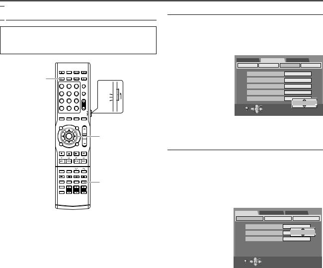
INITIAL SETTINGS

 Language
●Turn on the unit.
●Turn on the TV and select an input mode such as EXT1.
●Set the remote control selector switch to AUDIO.
●Press DVD on the remote control.
DVD
1 2 3
4 |
5 |
6 |
AUDIO |
|
|
|
TV |
7 |
8 |
9 |
SAT |
0
VOL |
Selection Keys |
|
|
|
(FGDE) |
|
ENTER |
SET UP
On-screen Language Set
This unit offers you the choice to view on-screen messages in 10 different languages.
1Press SET UP to access the Main Menu screen.
2Press selection keys to select AFUNCTION SET UPB, then press ENTER for confirmation.
3Press selection keys to select ADISPLAY SETB, then press ENTER for confirmation.
4Press selection keys to select AON SCREEN LANGUAGEB, then press ENTER.
5Press selection keys to select your desired language, then press
ENTER.
DVD SET UP |
FUNCTION SET UP INITIAL SET UP |
|||
VIDEO IN/OUT |
RECORDING SET |
DISPLAY SET |
OTHERS |
|
SUPERIMPOSE |
AUTO |
|
||
GREY BACK |
ON |
|
||
DIMMER |
|
BRIGHT |
|
|
POWER SAVE |
OFF |
|
||
ON SCREEN LANGUAGE |
ENGLISH |
|
||
SET UP |
OK |
ENGLISH |
||
SELECT WITH [CURSORS] |
||||
|
|
|||
EXIT |
SELECT |
THEN PRESS [ENTER] |
||
|
|
|||
6 Press SET UP to complete the setting.
Menu/Audio/Subtitle Language Set
Some DVD discs contain the DVD menu display, audio and subtitles in multiple languages. With these discs, you can set the default language as you like.
●The procedure shows how to set AMENU LANGUAGEB as an example.
1Press SET UP to access the Main Menu screen.
2Press selection keys to select ADVD SET UPB, then press ENTER for confirmation.
3Press selection keys
to select ALANGUAGE |
DVD SET UP |
FUNCTION SET UP |
INITIAL SET UP |
||
LANGUAGE SET |
AUDIO OUTPUT |
UTILITY |
|||
SETB, then press |
|||||
|
|
|
|
||
ENTER for |
MENU LANGUAGE |
|
ENGLISH |
||
confirmation. |
AUDIO LANGUAGE |
|
ENGLISH |
||
4 Press selection keys |
|
|
|
ENGLISH |
|
SUBTITLE |
|
|
OFF |
||
|
|
|
|||
to select AMENU |
|
|
|
|
|
LANGUAGEB, then |
|
|
|
|
|
press ENTER for |
SET UP |
OK |
SELECT WITH [CURSORS] |
||
confirmation. |
EXIT |
SELECT |
THEN PRESS [ENTER] |
||
5Press selection keys
to select your desired language, then press ENTER.
●See ALanguage Code ListB (A pg. 90).
6Press SET UP to complete the setting.
NOTE:
When the selected language is not available on the disc, the disc’s default menu language is played back.
20
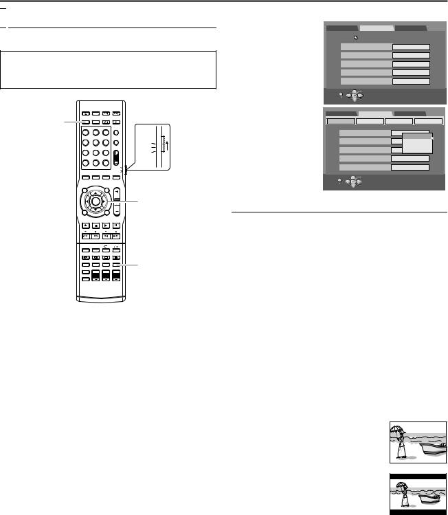
INITIAL SETTINGS

 Monitor Set
You can select the monitor type depending on the TV used when you play back DVD VIDEO discs recorded for wide-screen TVs.
●Turn on the unit.
●Turn on the TV and select an input mode such as EXT1.
●Set the remote control selector switch to AUDIO.
●Press DVD on the remote control.
DVD
1 2 3
4 |
5 |
6 |
AUDIO |
|
|
|
TV |
7 |
8 |
9 |
SAT |
0
VOL |
Selection Keys |
|
|
|
(FGDE) |
|
ENTER |
SET UP
1 Press SET UP to access the Main Menu screen.
2
DVD SET UP |
FUNCTION SET UP INITIAL SET UP |
||
VIDEO IN/OUT |
RECORDING SET |
DISPLAY SET |
OTHERS |
3Press selection keys to select AVIDEO IN/OUTB, then press ENTER.
4Press selection keys to select AMONITOR TYPEB, then press
ENTER.
5Press selection keys to select the desired setting, then press
ENTER.
6Press SET UP to complete the setting.
MONITOR TYPE |
4:3LB |
|
|
F-1 INPUT |
VIDEO |
|
|
L-1 INPUT |
VIDEO |
|
|
L-1 OUTPUT |
SCART VIDEO |
||
L-2 SELECT |
S-VIDEO/RGB |
||
SET UP |
OK |
SELECT WITH [CURSORS] |
|
EXIT |
SELECT |
THEN PRESS [ENTER] |
|
|
|
||
DVD SET UP |
FUNCTION SET UP INITIAL SET UP |
||
VIDEO IN/OUT |
RECORDING SET |
DISPLAY SET |
OTHERS |
MONITOR TYPE |
4:3LB |
|
|
|
|
4:3LB |
|
F-1 INPUT |
VIDEO4:3PS |
||
|
|
16:9AUTO |
|
L-1 INPUT |
VIDEO16:9FIX |
||
L-1 OUTPUT |
SCART VIDEO |
||
L-2 SELECT |
S-VIDEO/RGB |
||
SET UP |
OK |
SELECT WITH [CURSORS] |
|
EXIT |
SELECT |
THEN PRESS [ENTER] |
|
|
|
||
* The boldface settings below indicate the settings at your purchase.
8 MONITOR TYPE ^ 4:3LB / 4:3PS / 16:9AUTO / 16:9FIX
4:3LB (Letter Box conversion):
Select this when the aspect ratio of your TV is 4:3 (conventional TV). While viewing a wide screen picture, the black bars appear on the top and the bottom of the screen.
4:3PS (Pan&Scan):
Select this when the aspect ratio of your TV is 4:3 (conventional TV). While viewing a wide screen picture, the black bars do not appear; however, the left and right edges of the pictures will not be shown on the screen.
16:9AUTO (Wide television conversion):
Select this when the aspect ratio of your TV is 16:9 (wide TV).
16:9FIX (Wide television conversion):
Select this when the aspect ratio of your TV is fixed to 16:9 (wide TV). The unit automatically adjusts the screen width of the output signal correctly when playing back a picture whose aspect ratio is 4:3.
Pan&Scan/Letter Box
In general, DVD VIDEO disc are produced for a wide-screen TV with 16:9 aspect ratio.
Material with this ratio will not fit to a TV with 4:3 aspect ratio. There are two styles to display the image, APan&ScanB (PS) and ALetter BoxB (LB).
Pan&Scan
The right and left side of the image are cut off. The image fills the screen.
● The picture will be shown in the A4:3LBB mode depending on the disc even if the A4:3PSB mode is selected.
Letter Box
Black bands appear at the top and bottom of the image. The image itself appears in 16:9 aspect ratio.
21
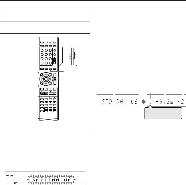
INITIAL SETTINGS

 Speaker Set
To obtain superior sound effects, you need to perform the speaker and subwoofer setting after all connections have been completed.
●Turn on the unit.
●Set the remote control selector switch to AUDIO.
●Press DVD on the remote control.
DVD
1 |
2 |
3 |
|
4 |
5 |
6 |
AUDIO |
|
|
|
TV |
7 |
8 |
9 |
SAT |
|
0 |
|
|
SETTING
VOL |
Selection Keys |
(FGDE)
ENTER
SMART S.SET UP 
Smart Surround Setup
The distance from the listening position to the speakers is one of the important elements to obtain the best possible sound effects. By using Smart Surround Setup, the following are automatically calculated by one simple action^clapping hands.
●Speaker distance (with comparison to the nearest speaker)
●Speaker output level (except the subwoofer)
1Take position from where you listen to the sound.
● Make sure the speaker cables are securely connected.
2Press and hold SMART S.SET UP until ASETTING UPB blinks on the front display panel.
L |
|
|
|
R SW |
||
|
|
|
|
|
|
|
 PL
PL
3After confirming that ASETTING UPB stops blinking, clap your hand over your head once while ASETTING UPB still remains lit.
●The unit starts detecting the level of the sound coming through each speakers (except the subwoofer).
NOTES:
●In order to set the speaker information effectively using the Smart Surround Setup, the AC plug of all devices, which are potential noise sources, connected to the unit or subwoofer should be removed.
●Before starting Smart Surround Setup, set the speaker information correctly with respect to each speaker except for the subwoofer.
●When the setting is made using Smart Surround Setup, the speaker distance and output level you have set before will be invalid.
●If you have turned off the front display panel, cancel Dimmer. Otherwise, you cannot see the information on the front display panel during Smart Surround Setup.
●Smart Surround Setup may not be properly performed if the clapping sound is blocked.
●When you change the speakers, perform the procedures from step 1 again.
When the clapping sound is detected successfully,
ASUCCESSFULB appears on the front display panel, and the values set are shown as follows.
Example:
A B C D
L  C
C  R
R 
RS  LS
LS
AStandard channel (the nearest speaker).
This speaker position now works as the reference position (0 m) and the distance of the other speakers is shown by the difference with this reference speaker position.
BL: Left front speaker R: Right front speaker
C: Centre speaker
LS: Left surround speaker
RS: Right surround speaker
CDifference of each speaker position in distance (m)
DOutput level (-6 dB – +6 dB) of each speaker
When the clapping sound is not detected correctly,
ASETTING UPB appears again after one of the following messages appears. In this case, repeat step 3.
SILENT:
●The unit detects sound from only the left and right front speakers.
●The unit detects no sound from the front speakers and detects sound from at least one of the other speakers.
SILENT-ALL:
●The unit did not detect any sound from any speakers for about 12 seconds.
FAILED:
● The unit cannot detect sound from the left or right front speaker.
When 3 consecutive detections failed,
MANUAL:
●Smart Surround Setup ends after the message is displayed. Perform ASetting The Speaker DistanceB (A pg. 23).
22
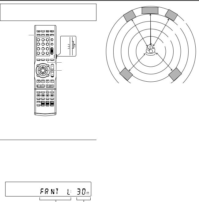
INITIAL SETTINGS
●Turn on the unit.
●Turn on the TV and select an input mode such as EXT1.
●Set the remote control selector switch to AUDIO.
●Press DVD on the remote control.
DVD
1 |
2 |
3 |
|
4 |
5 |
6 |
AUDIO |
|
|
|
TV |
7 |
8 |
9 |
SAT |
|
0 |
|
|
SETTING
VOL |
Selection Keys |
(FGDE)
ENTER
There is a time limit when performing the following setting. If the time is up before completing the setting, re-perform from the beginning.
Setting The Speaker Distance
●This operation is not necessary if the Smart Surround Setup is successful.
●By setting the distance, the unit automatically sets the delay time of each speaker such that sound from each speaker can be heard at the same time.
1Press SETTING.
The item of the setting performed most recently is displayed on the front display panel.
2Press F or G to display the speaker setting on the front display panel.
|
CENTRE |
|
L |
FRNT |
R |
FRNT |
|
3.3m
3.0m
2.7m
2.4m
2.1m
SURR |
SURR |
R |
L |
|
|
|
|
|
Set the distance as follows for the above case: |
|
|
● Front speaker |
3.0 m |
|
● Centre speaker |
3.0 m |
|
● Surround speaker |
2.7 m |
|
Changes in the order of |
Speaker |
FRNT LNFRNT RNCENTER |
distance |
NSURR LNSURR R. |
|
3
4
Press selection keys to select the distance.
Each time you press D or E, the speaker distance changes from 0.3 m to 9.0 m in 0.3 m interval.
Repeat steps 2 - 3 as necessary.
23
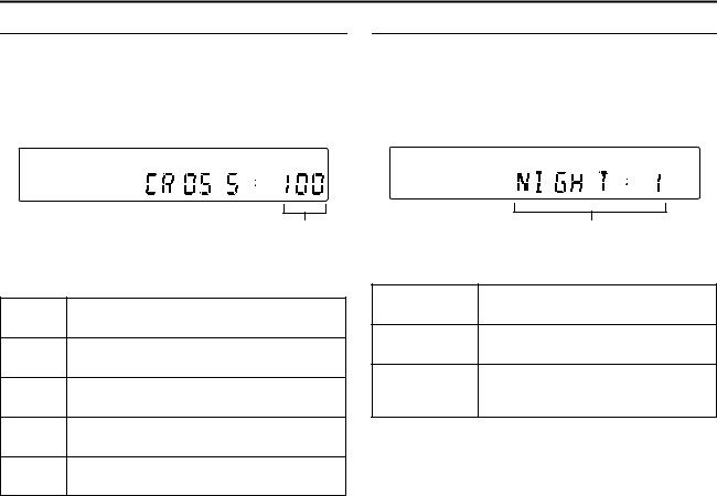
INITIAL SETTINGS
Setting The Crossover Frequency
By setting the crossover frequency, frequencies lower than the frequency being set is output from the subwoofer.
1Press SETTING.
The item of the setting performed most recently is displayed on the front display panel.
2Press F or G to display ACROSS :B on the front display panel.
3Press D or E to select the frequency.
Each time you press D or E, the display changes as follows: 80HzN100HzN120HzN150HzN200HzN (back to the beginning)
Select one of the crossover frequency according to size of the connected speaker.
80Hz
Select this when using cone speaker that is about 12 cm.
100Hz
Select this when using cone speaker that is about 10 cm.
120Hz
Select this when using cone speaker that is about 8 cm.
150Hz
Select this when using cone speaker that is about 6 cm. (Default)
200Hz
Select this when using cone speaker that is about 5 cm.
Setting The Midnight Mode
You can enjoy powerful sounds at night by setting the midnight mode.
1Press SETTING.
The item of the setting performed most recently is displayed on the front display panel.
2Press F or G to display ANIGHT :B on the front display panel.
3Press D or E to select the mode.
Each time you press D or E, the display changes as follows: NIGHT : 1NNIGHT : 2NNIGHT : OFFN (back to the beginning)
Select one of the following modes.
NIGHT : 1
Select this when you want to reduce the dynamic range slightly.
NIGHT : 2
Select this when you want to maximise the compression effect. (Ideal for midnight)
Select this when playing back using full NIGHT : OFF dynamic range. (Midnight mode not
activated) (Default)
24
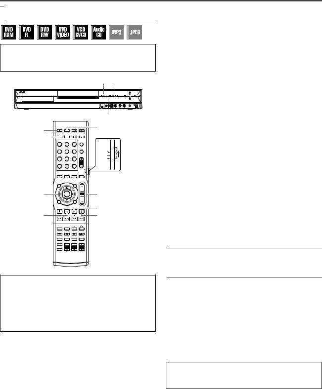
BASIC OPERATIONS ON DVD DECK

 Basic Playback
●Turn on the unit.
●Turn on the TV and select an input mode such as EXT1.
●Set the remote control selector switch to AUDIO.
●Press DVD on the remote control.
M o
|
|
|
|
I |
M |
|
|
|
TV/VIDEO |
|
|
|
|
|
DVD |
|
|
|
|
1 |
2 |
3 |
|
|
4 |
5 |
6 |
|
AUDIO |
|
|
|
|
TV |
7 |
8 |
9 |
|
SAT |
|
0 |
|
|
|
Selection Keys |
|
|
VOL |
VOL +/– |
(FGDE) |
|
|
|
|
|
|
|
|
ENTER
I
o |
W |
ATTENTION:
●It takes approximately 30 seconds to read a disc depending on the type and condition of the disc since this unit is multi-disc compatible (DVD-RAM, DVD-RW, DVD-R). It may even take several minutes when a disc is dirty, scratched or warped.
●It may take a few seconds to start playback. This is not a malfunction.
●Forward/reverse high-speed search and other operations cannot be performed while playback is stopped.
To play back an MP3/JPEG disc, see APlayback With MP3/JPEG NavigationB (A pg. 64).
1Load a disc.
●For details, refer to APlacing A DiscB (A pg. 5).
●Pressing M also closes the disc tray.
●Playback begins automatically if an auto-playback DVD disc is loaded.
2Press I to start playback.
●If you load a DVD disc whose region code does not match the unit, AREGION CODE ERROR CHECK DISCB appears on the TV screen. For details, refer to ARegion NumberB (A pg. 3).
●With Video CD/SVCD discs with PBC control or some DVD discs, the menu display may appear on the TV screen after starting playback. In this case, select an item which you want to play back from the menu. For details, refer to APlayback Control (PBC) FunctionB (A pg. 31) or ALocating A Desired Scene Using The DVD MenuB (A pg. 28).
●The Library Database Navigation also enables you to search and scan the beginning of the desired titles. (A pg. 56)
8Direct playback with Library Database Navigation
You can playback the desired title by specifying the track
number of the Audio CD.
ADuring playback or while stopped, press the number keys to enter the track number.
●To select track 8, press the number key A8B.
●To select track 21, press the number keys A2B and A1B.
●To select track 100, press the number keys A1B, A0B then A0B again.
BPress ENTER while the track number is blinking.
●The entry will be disregarded if ENTER is not pressed within 5 seconds while the track number is blinking.
●If the number entered exceeds the number of tracks recorded on the Audio CD, A7B appears on the TV screen.
The entry will be disregarded.
●The TV screen will display the 3 digit number. The front display panel displays only the 2 digit number.
To Pause Playback
1Press W to pause playback.
●To resume normal playback, press I.
To Stop Playback
1Press o to stop playback.
●When a recordable disc is played, playback stops and a programme received with the unit’s tuner resumes on the TV screen.
●When a playback-only disc is played, playback stops and the TV screen becomes all blue when you press o. Pressing o again resumes a programme received with the unit’s tuner.
●If M is pressed during playback, playback stops, then the disc tray opens.
NOTE:
When the Library Database Navigation screen appears, choose a thumbnail image of the desired title on the TV screen, then press ENTER. (A pg. 56)
Each time you press TV/VIDEO, the unit switches between video mode (or connected external mode) and TV mode. (A pg. 8) AzB lights on the front display panel when video mode is selected. (A pg. 8)
25
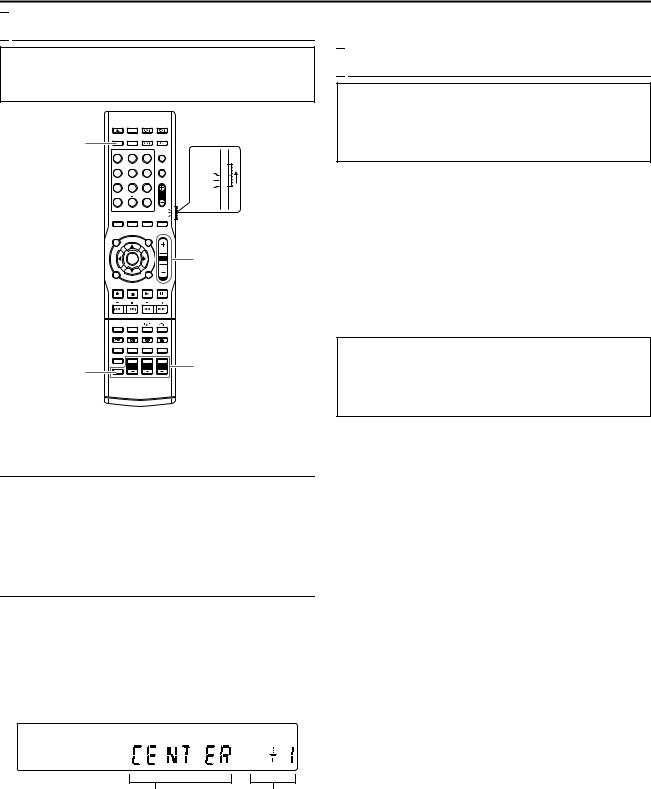
BASIC OPERATIONS ON DVD DECK

 Adjusting The Volume
●Turn on the unit.
●Turn on the TV and select an input mode such as EXT1.
●Set the remote control selector switch to AUDIO.
●Press DVD on the remote control.
DVD
1 |
2 |
3 |
|
4 |
5 |
6 |
AUDIO |
|
|
|
TV |
7 |
8 |
9 |
SAT |
|
0 |
|
|
VOL |
VOL +/– |
SHIFT |
Speaker output |
adjustment buttons |
There is a time limit when performing the following setting. If the time is up before completing the setting, re-perform from the beginning.
Adjusting The Volume
The volume is always set to the lowest level before operation starts no matter what source (sound source) is to be played back.
If the volume is set at its high level, the sudden blast of sound energy may impair your hearing or damage your speakers.
Press VOL +/– on the remote control.
+ : To increase the volume. - : To turn down the volume.
Adjusting The Output Level Of Each Speaker
Adjust with the speaker output adjustment buttons for each speaker.
●Press CENTER +/– to adjust the centre speaker.
●Press L +/– to adjust the left front speaker.
●Press R +/– to adjust the right front speaker.
●Press SHIFT and S. WFR +/– to adjust the subwoofer.
●Press SHIFT and SURR. L +/– to adjust the left surround speaker.
●Press SHIFT and SURR. R +/– to adjust the right surround speaker.
During HEADPHONE: Not adjustable except for L and R. During TV DIRECT: All speakers not adjustable.

 Listening With Headphones
ATTENTION:
Be sure to turn down the volume;
●before connecting or putting on the headphones, as high volume may damage both the headphones and your hearing.
●before removing the headphones, as high volume will result in a full blast from the speakers.
You can enjoy stereo software as well as multi-channel software through the headphones. (Sounds are down-mixed to the front channels while playing multi-channel software.)
Connect the headphones to the headphone jack [PHONES] on the front panel of the centre unit.
●If Surround is activated, A3D H PHONEB lights up for a few seconds and ADSPB lights on the front display panel.
●If Surround is deactivated, AHEADPHONEB lights up for a few seconds on the front display panel.
●When the headphone is inserted, the unit switches between A3D H PHONEB mode and AHEADPHONEB mode each time SURROUND is pressed.
●There is no sound output from the speakers when the headphone is inserted.
3D Headphone Mode^3D H PHONE
You can also enjoy the Surround mode through the headphones.
If Surround is activated, 3D headphone mode will be activated regardless of the software type being played.
A3D H PHONEB and ADSPB light on the front display panel.
Speaker |
Can be set from -6 dB to |
|
+6 dB in 1 dB interval. |
●Adjustment cannot be made for speakers whose indication is not lighted.
During SURR OFF: C, SL and SR not adjustable.
During AUTO SURR (with 2-channel signal input): C, SL and SR not adjustable.
26
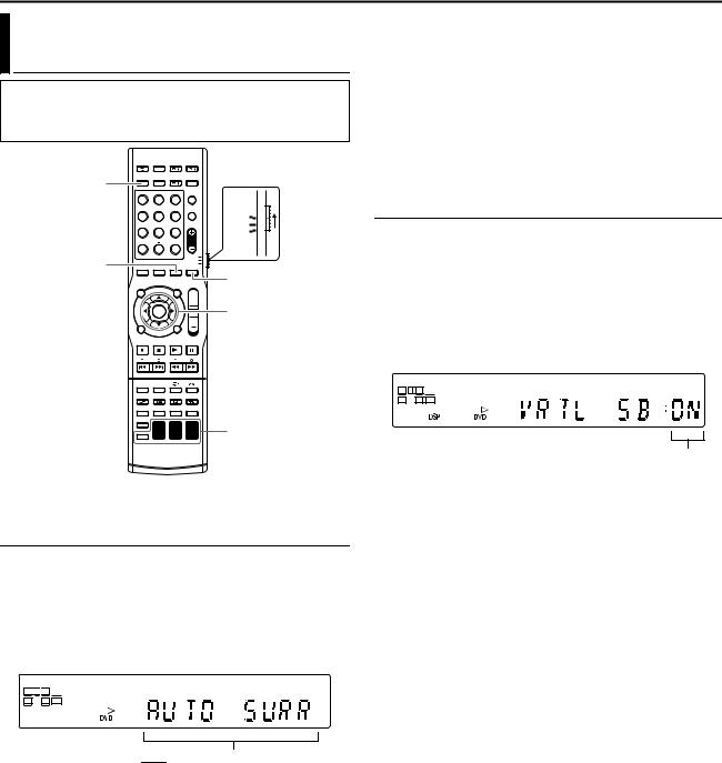
BASIC OPERATIONS ON DVD DECK
Setting Auto Surround And Virtual
Surround Back
●Turn on the unit.
●Turn on the TV and select an input mode such as EXT1.
●Set the remote control selector switch to AUDIO.
●Press DVD on the remote control.
DVD
1 |
2 |
3 |
|
4 |
5 |
6 |
AUDIO |
|
|
|
TV |
7 |
8 |
9 |
SAT |
|
0 |
|
|
SETTING |
|
|
|
|
|
|
SURROUND |
|
|
VOL |
Selection Keys |
|
|
|
(FGDE) |
ENTER


 Speaker output

 adjustment buttons
There is a time limit when performing the following setting. If the time is up before completing the setting, re-perform from the beginning.
Setting Auto Surround
Auto Surround works when the unit detects the incoming digital signal. In other words, it is activated under the following cases.
●When a digital sound source is selected.
●When the input mode changes from analogue to digital.
1Press SURROUND repeatedly.
2AAUTO SURRB lights on the front display panel.
3Each time you press SURROUND, the Surround mode switches in the following order.
L 
 C
C
 R SW
R SW
LS |
RS LFE |
 D
D
AUTO SURRNDOLBY D (or DTS)*NTHEATER1N THEATER2NHALL1NHALL2NLIVE CLUBNDANCE CLUBN PAVILIONNALL CH STNSURR OFFN (back to the beginning)
*The display changes as follows according to the sound source.
●During 2-channel source NPL II MOVIENPL II MUSIC
●During DUAL MONO NDUAL MONON
|
● If a multi-channel signal is detected, |
|
an appropriate Surround mode will be |
|
activated. |
|
● If a Dolby Digital II-channel signal with |
|
surround signal is detected, |
AUTO SURR |
PL II MOVIE will be selected. |
|
● If a Dolby Digital II-channel signal |
|
without surround signal is detected, |
|
ASURR OFFB will be selected. |
|
● If a Linear PCM signal is detected, |
|
nothing changes. |
|
|
SURR OFF |
Deactivates Auto Surround. |
|
|
Setting Virtual Surround Back
You can enjoy the effect of Virtual Surround Back when playing back Dolby Digital EX or DTS-ES software without Surround Back speakers. This function creates sound effects from behind as if Surround Back speakers are connected.
1Press SETTING.
The item of the setting performed most recently is displayed on the front display panel.
2Press selection keys to display AVRTL SB :B on the front display panel.
3Press selection keys to select AVRTL SB : ONB.
L |
C R SW |
|||
LS |
|
|
RS LFE |
|
|
D |
|
|
|
|
Switches between |
|
ON-OFF. |
|
|
VIRTUAL |
AVRTL SB : ONB lights on the front |
SURROUND |
display panel when playing back Dolby |
BACK ON |
Digital EX or DTS-ES software. |
|
|
VIRTUAL |
Select to deactivate Virtual Surround |
SURROUND |
Back. |
BACK OFF |
|
|
|
27
 Loading...