


 Loading...
COMPACT COMPONENT SYSTEM
MX-GT88— Consists of CA-MXGT88 and SP-MXGT88 MX-GA77— Consists of CA-MXGA77 and SP-MXGA77
MP3
MP3
SP-MXGT88 |
|
|
1 |
2 |
3 |
R O C K |
|
|
|
D A N C E |
P O P |
|
|
|
H A L L |
CLASSIC |
|
|
|
STADIUM |
|
VO |
LUME |
|
|
|
D |
|
|
|
UN |
MODE |
|
|
PRESET |
SOUND |
|
|
|
TAPE A /B |
TURBO |
|
|
|
EJECT |
EJECT |
CA-MXGT88
SP-MXGT88 |
|
|
1 |
2 |
3 |
R O C K |
|
|
|
D A N C E |
P O P |
|
|
|
H A L L |
CLASSIC |
|
|
|
STADIUM |
|
VO |
LUME |
|
|
|
D |
|
|
|
UN |
MODE |
|
|
PRESET |
SOUND |
|
|
|
TAPE A /B |
TURBO |
|
|
|
EJECT |
EJECT |
SP-MXGA77 CA-MXGA77 SP-MXGA77
INSTRUCTIONS
For Customer Use:
Enter below the Model No. and Serial No. which are located either on the rear, bottom or side of the cabinet. Retain this information for future reference.
Model No.
Serial No.
LVT1010-001B
[J]
Warnings, Cautions and Others
Mises en garde, précautions et indications diverses
|
|
CAUTION |
|
|
|
|
|
|
|
RISK OF ELECTRIC SHOCK |
|
|
|
DO NOT OPEN |
|
|
|
|
|
|
|
|
|
CAUTION: |
TO REDUCE THE RISK OF ELECTRIC SHOCK. |
||
|
DO NOT REMOVE COVER (OR BACK) |
||
|
NO USER SERVICEABLE PARTS INSIDE. |
||
REFER SERVICING TO QUALIFIED SERVICE PERSONNEL.
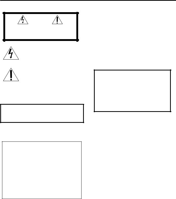
The lightning flash with arrowhead symbol, within an equilateral triangle is intended to alert the user to the presence of uninsulated “dangerous voltage” within the product's enclosure that may be of sufficient magnitude to constitute a risk of electric shock to persons.
The exclamation point within an equilateral triangle is intended to alert the user to the presence of important operating and maintenance (servicing) instructions in the literature accompanying the appliance.
WARNING: TO REDUCE THE RISK OF FIRE OR ELECTRIC SHOCK, DO NOT EXPOSE THIS APPLIANCE TO RAIN OR MOISTURE.
For U.S.A.
This equipment has been tested and found to comply with the limits for a Class B digital device, pursuant to part 15 of the FCC Rules. These limits are designed to provide reasonable protection against harmful interference in a residential installation.
This equipment generates, uses and can radiate radio frequency energy and, if not installed and used in accordance with the instructions, may cause harmful interference to radio communications. However, there is no guarantee that interference will not occur in a particular installation. If this equipment does cause harmful interference to radio or television reception, which can be determined by turning the equipment off and on, the user is encouraged to try to correct the interference by one or more of the following measures:
Reorient or relocate the receiving antenna.
Increase the separation between the equipment and receiver. Connect the equipment into an outlet on a circuit different from that to which the receiver is connected.
Consult the dealer or an experienced radio/TV technician for help.
CAUTION
To reduce the risk of electrical shocks, fire, etc.:
1.Do not remove screws, covers or cabinet.
2.Do not expose this appliance to rain or moisture.
ATTENTION
Afin d’éviter tout risque d’électrocution, d’incendie, etc.:
1.Ne pas enlever les vis ni les panneaux et ne pas ouvrir le coffret de l’appareil.
2.Ne pas exposer l’appareil à la pluie ni à l’humidité.
Caution ––  STANDBY/ON switch!
Disconnect the mains plug to shut the power off completely. The  STANDBY/ON switch in any position does not disconnect the mains line. The power can be remote controlled.
Attention –– Commutateur  STANDBY/ON!
Déconnecter la fiche de secteur pour couper complètement le courant. Le commutateur  STANDBY/ON ne coupe jamais complètement la ligne de secteur, quelle que soit sa position. Le courant peut être télécommandé.
1.CLASS 1 LASER PRODUCT
2.CAUTION: Invisible laser radiation when open and interlock failed or defeated. Avoid direct exposure to beam.
3.CAUTION: Do not open the top cover. There are no user serviceable parts inside the Unit; leave all servicing to qualified service personnel.
1.PRODUIT LASER CLASSE 1
2.ATTENTION: Radiation laser invisible quand l'appareil est ouvert ou que le verrouillage est en panne ou désactivé. Eviter une exposition directe au rayon.
3.ATTENTION: Ne pas ouvrir le couvercle du dessus. Il n'y a aucune pièce utilisable à l'intérieur. Laisser à un personnel qualifié le soin de réparer votre appareil.
G-1

For Canada/pour le Canada
CAUTION: TO PREVENT ELECTRIC SHOCK, MATCH WIDE BLADE OF PLUG TO WIDE SLOT, FULLY INSERT. ATTENTION: POUR EVITER LES CHOCS ELECTRIQUES, INTRODUIRE LA LAME LA PLUS LARGE DE LA FICHE DANS LA BORNE CORRESPONDANTE DE LA PRISE ET POUSSER JUSQUAU FOND.
For Canada/pour le Canada
THIS DIGITAL APPARATUS DOES NOT EXCEED THE CLASS B
LIMITS FOR RADIO NOISE EMISSIONS FROM DIGITAL
APPARATUS AS SET OUT IN THE INTERFERENCE-CAUSING EQUIPMENT STANDARD ENTITLED “DIGITAL APPARATUS,”
ICES-003 OF THE DEPARTMENT OF COMMUNICATIONS.
CET APPAREIL NUMERIQUE RESPECTE LES LIMITES DE BRUITS RADIOELECTRIQUES APPLICABLES AUX APPAREILS
NUMIRIQUES DE CLASSE B PRESCRITES DANS LA NORME
SUR LE MATERIEL BROUILLEUR: “APPAREILS NUMERIQUES”, NMB-003 EDICTEE PAR LE MINISTRE DES
COMMUNICATIONS.
Caution: Proper Ventilation
To avoid risk of electric shock and fire, and to prevent damage, locate the apparatus as follows:
1 Front:
No obstructions and open spacing. 2 Sides/ Top/ Back:
No obstructions should be placed in the areas shown by the dimensions below.
3 Bottom:
Place on the level surface. Maintain an adequate air path for ventilation by placing on a stand with a height of 10 cm or more.
Attention: Aération correcte
Pour prévenir tout risque de décharge électrique ou d’incendie et éviter toute détérioration, installez l’appareil de la manière suivante: 1 Avant:
Bien dégagé de tout objet. 2 Côtés/dessus/dessous:
Assurez-vous que rien ne bloque les espaces indiqués sur le schéma ci-dessous.
3 Dessous:
Posez l’appareil sur une surface plane et horizontale.Veillez à ce que sa ventilation correcte puisse se faire en le plaçant sur un support d’au moins dix centimètres de hauteur.
Front view |
|
|
|
|
|
15 cm |
|
|
|
|
|
|
|
|
Side view |
|
|
15 cm |
||||
Face |
|
|
|
|
|
|
|
|
|
|
|
|
|
Côté |
|
|
||||||
|
|
|
|
|
|
|
(5 15/16 in.) |
|
|
|
|
|
|
|
|
(5 15/16 in.) |
||||||
|
|
|
|
1 cm |
|
|
1 cm |
|
|
|
|
|
|
|
|
|
|
|||||
15 cm |
|
|
|
|
|
|
|
|
|
|
15 cm |
|
|
|
|
|||||||
|
(7/16 in.) |
|
|
(7/16 in.) |
|
|
|
|
|
|
|
|
|
|
||||||||
(5 15/16 in.) |
|
|
|
|
|
|
|
|
(5 |
15/16 in.) |
|
|
|
|
||||||||
|
|
|
|
|
|
|
|
|
|
|
||||||||||||
|
|
SP-MXGT88 |
|
|
|
CA-MXGT88 |
|
|
SP-MXGT88 |
|
|
|
|
15 cm |
CA-MXGT88 |
|
||||||
|
|
|
|
|
|
|
|
|
(5 15/16 in.) |
|
|
|||||||||||
|
|
|
|
|
|
|
||||||||||||||||
|
|
SP-MXGA77 |
|
CA-MXGA77 |
|
|
SP-MXGA77 |
|
|
|
|
|
|
|
|
CA |
-MXGA77 |
|
||||
|
|
|
|
|
|
|
|
|
||||||||||||||
|
|
|
|
|
|
|
|
|
|
|
|
|
|
|
|
|
|
|
|
|
|
|
|
|
|
|
|
|
|
|
|
|
|
|
|
|
|
10 cm |
|
|
|
|
|||
|
|
|
|
|
|
|
|
|
|
|
|
|
|
|
|
|
|
|
||||
|
|
|
|
|
|
|
|
|
|
|
|
|
|
|
|
|
|
|
||||
|
|
|
|
|
|
|
|
|
|
|
|
|
|
|
(3 15/16 in.) |
|
|
|
|
|||
|
|
|
|
|
|
|
|
|
|
|
|
|
|
|
|
|
|
|
|
|
|
|
G-2
Introduction
We would like to thank you for purchasing one of our JVC products. Before operating this unit, read this manual carefully and thoroughly to obtain the best possible performance from your unit, and retain this manual for future reference.
About This Manual
This manual is organized as follows:
•The manual mainly explains operations using the buttons and controls on the unit. You can also use the buttons on the remote control if they have the same or similar names (or marks) as those on the unit.
If operation using the remote control is different from that using the unit, it is then explained.
•Basic and common information that is the same for many functions is grouped in one place, and is not repeated in each procedure. For instance, we do not repeat the information about turning on/off the unit, setting the volume, changing the sound effects, and others, which are explained in the section “Common Operations” on pages 9 to 11.
•The following marks are used in this manual:
Gives you warnings and cautions to prevent damage or risk of fire/electric shock.
Also gives you information which is not good for obtaining the best possible performance from the unit.
Gives you information and hints you had better know.
Precautions
Installation
•Do not grasp the control knobs when moving or carrying the unit.
•Install in a place which is level, dry and neither too hot nor too cold—between 5˚C (41˚F) and 35˚C (95˚F).
•Install the unit in a location with adequate ventilation to prevent internal heat built-up in the unit.
•Leave sufficient distance between the unit and the TV.
•Keep the speakers away from the TV to avoid interference with TV.
DO NOT install the unit in a location near heat sources, or in a place subject to direct sunlight, excessive dust or vibration.
Power sources
•When unplugging from the wall outlet, always pull the plug, not the AC power cord.
DO NOT handle the AC power cord with wet hands.
Moisture condensation
Moisture may condense on the lens inside the unit in the following cases:
•After starting heating in the room
•In a damp room
•If the unit is brought directly from a cold to a warm place Should this occur, the unit may malfunction. In this case, leave the unit turned on for a few hours until the moisture evaporates, unplug the AC power cord, and then plug it in again.
Others
•Should any metallic object or liquid fall into the unit, unplug the unit and consult your dealer before operating any further.
•If you are not going to operate the unit for an extended period of time, unplug the AC power cord from the wall outlet.
DO NOT disassemble the unit since there are no user serviceable parts inside.
If anything goes wrong, unplug the AC power cord and consult your dealer.
1

Contents
Location of the Buttons and Controls ....................... |
3 |
Front Panel ................................................................. |
3 |
Remote Control .......................................................... |
5 |
Getting Started ............................................................ |
6 |
Unpacking .................................................................. |
6 |
Putting the Batteries into the Remote Control ........... |
6 |
Connecting Antennas ................................................. |
6 |
Connecting Speakers .................................................. |
7 |
Connecting Other Equipment ..................................... |
8 |
Canceling the Display Demonstration ....................... |
8 |
Common Operations .................................................. |
9 |
Turning On or Off the Power ....................................... |
9 |
Setting the Clock ........................................................ |
9 |
Selecting the Sources................................................... |
9 |
Adjusting the Volume ............................................... |
10 |
Reinforcing the Bass Sound ..................................... |
10 |
Enjoying the Heavy Sound ....................................... |
10 |
Selecting the Sound Modes ...................................... |
11 |
Turning On or Off the Key-touch Tone .................... |
11 |
Listening to the Radio .............................................. |
12 |
Tuning in to a Station—Auto Search ....................... |
12 |
Presetting Stations .................................................... |
12 |
Tuning in to a Preset Station .................................... |
12 |
Playing Back CDs ..................................................... |
13 |
Loading CDs ............................................................ |
13 |
Playing Back CDs—All Disc and One Disc ............ |
13 |
Basic CD Operations ................................................ |
15 |
Changing the MP3 Playback Mode.......................... |
17 |
Turning On or Off the Resume Play for MP3 Disc .. |
17 |
Programming the Playing Order of the Tracks |
|
—Program Play .................................................. |
18 |
Playing at Random—Random Play ......................... |
19 |
Repeating Tracks or CDs—Repeat Play .................. |
19 |
Prohibiting Disc Ejection—Carrousel Lock ............ |
19 |
Playing Back Tapes ................................................... |
20 |
Playing Back a Tape ................................................. |
20 |
Recording .................................................................. |
21 |
Recording a Tape on Deck B .................................... |
21 |
Dubbing Tapes .......................................................... |
22 |
CD Synchronized Recording ..................................... |
22 |
Using the Timers ....................................................... |
23 |
Using Daily Timer .................................................... |
23 |
Using Recording Timer ............................................ |
24 |
Using Sleep Timer .................................................... |
25 |
Timer Priority ........................................................... |
25 |
Maintenance .............................................................. |
26 |
Troubleshooting ........................................................ |
27 |
Specifications ............................................................. |
28 |
2
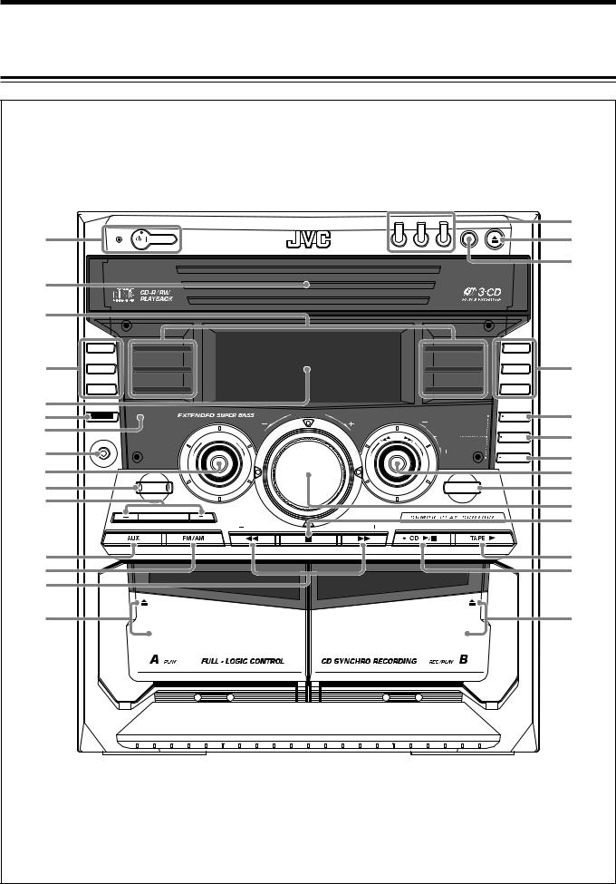
Location of the Buttons and Controls
Become familiar with the buttons and controls on your unit.
Front Panel
|
|
|
|
|
|
|
CD 1 |
CD 2 |
CD 3 |
|
y |
|
|
|
|
|
|
|
|
|
DISC CHANGE |
|
|
1 |
STANDBY |
|
|
|
|
|
|
|
|
|
u |
|
STANDBY/ON |
|
|
|
|
|
|
|
|
||
|
|
|
|
|
|
|
|
|
|
||
|
|
|
|
|
|
|
|
|
|
|
i |
2 |
|
|
|
|
|
|
|
|
|
|
|
3 |
|
|
|
|
|
|
|
|
|
|
|
|
REC START |
R O C K |
|
|
|
|
|
|
D A N C E |
REPEAT |
|
|
/ STOP |
|
|
|
|
|
|
|
|||
4 |
CD REC |
P O P |
|
|
|
|
|
|
H A L L |
PROGRAM |
o |
START |
|
|
|
|
|
|
|||||
|
|
|
|
|
|
|
|
|
|||
|
|
|
|
|
|
|
|
|
|
||
|
DUBBING |
CLASSIC |
|
|
|
|
|
|
STADIUM |
RANDOM |
|
5 |
|
|
|
|
LU |
ME |
|
|
|
|
|
6 |
|
|
|
|
|
|
|
CLOCK |
; |
||
DISPLAY |
|
|
|
VO |
|
|
|
||||
|
|
|
|
|
|
|
|
/ TIMER |
|||
|
|
|
|
|
|
|
|
|
|||
|
|
|
|
|
|
|
|
|
|
||
7 |
PHONES |
|
ND |
MO |
|
|
|
|
PRESET |
SET |
a |
|
|
U |
D |
|
|
|
|
||||
|
|
O |
|
|
|
|
|
|
|
||
|
|
S |
|
|
E |
|
|
|
|
|
|
8 |
|
|
|
|
|
|
|
|
|
CANCEL |
s |
|
|
|
|
|
|
|
|
|
/ DEMO |
||
9 |
|
|
|
|
|
|
|
|
|
|
d |
p |
|
SOUND |
|
|
|
|
|
|
TAPE A /B |
|
f |
|
TURBO |
|
|
|
|
|
|
|
|||
|
|
|
|
|
|
|
|
|
|||
q |
|
|
|
|
|
|
|
|
|
|
g |
|
|
|
|
|
|
|
|
|
|
|
|
|
|
SUBWOOFER LEVEL |
|
|
|
|
|
|
|
|
h |
|
|
|
|
|
TUNING |
|
TUNING |
|
|
|
|
|
|
|
|
|
|
|
|
|
|
||
w |
|
|
|
|
|
BEEP |
|
|
|
|
j |
|
|
|
|
|
|
|
|
|
|
||
e |
|
|
|
|
|
|
|
|
|
|
k |
r |
|
|
|
|
|
|
|
|
|
|
|
|
|
EJECT |
|
|
|
|
|
|
EJECT |
|
|
t |
|
|
|
|
|
|
|
|
|
|
l |
3 |
|
|
|
|
|
|
|
|
|
|
|
Continued 
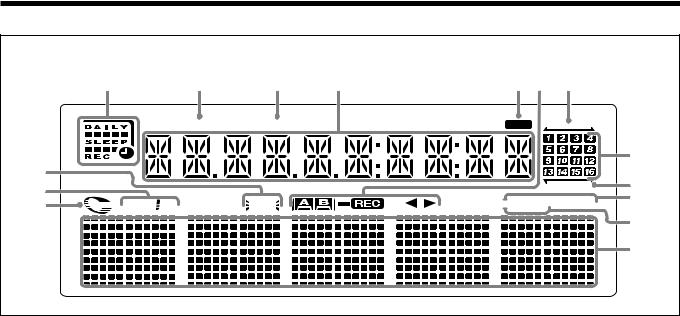
Display Window
1 |
2 |
3 |
4 |
5 6 |
7 |
|
GROUP |
TRACK |
|
MP3 |
|
8 |
9 |
0 |
TURBO
WOOFER 
SOUND |
REPEAT ALL 1 DISC |
MODE |
MONO ST |
-
=
~
!
@
See pages in the parentheses for details.
Front Panel
1  STANDBY/ON button and STANDBY lamp (9, 24, 25)
2 Carrousel
3 Sound mode lamps (11)
4REC START/STOP button (21) CD REC START button (22) DUBBING button (22)
5 Display window
6 DISPLAY button (9)
7 Remote sensor
8 PHONES jack (10)
9 SOUND MODE control (11) p SOUND TURBO button (10)
q SUBWOOFER LEVEL +/– buttons (10)
wAUX button (9)
Pressing this button also turns on the unit.
eFM/AM button (9, 12)
Pressing this button also turns on the unit.
rTUNING +/– buttons (12)
1/ ¡(fast rewind/fast forward) buttons (15, 20) t Deck A cassette holder (20, 22)
Pressing the 0EJECT portion opens the holder.
y Disc number buttons and lamps (CD1, CD2, and CD3) (14, 15, 18, 19, 22)
Pressing one of these buttons also turns on the unit. u 0(Carrousel open/close) button (13 – 15, 17 – 19)
Pressing this button also turns on the unit. i DISC CHANGE button (13, 15)
o REPEAT button (13, 15, 19)
PROGRAM (MP3 Resume on/off) button (17, 18) RANDOM button (19)
; CLOCK/TIMER button (9, 23 – 25) a SET button (9, 12, 18, 23 – 25)
s CANCEL/DEMO button (8, 9, 18, 24, 25)
dPRESET +/– control (12)
4/¢(reverse search/forward search) control (9, 15 – 19, 23 – 25)
f TAPE A/B button (20) g VOLUME control (10)
h7(stop) button (13 – 15, 18 – 22) BEEP button (11)
jTAPE 3(play) button (9, 20, 22)
Pressing this button also turns on the unit.
kCD 6(play/pause) button (9, 13 – 15, 18)
Pressing this button also turns on the unit.
lDeck B cassette holder (20 – 22, 24)
Pressing the EJECT 0portion opens the holder.
Display window
1Timer indicators
• DAILY (daily timer), SLEEP (sleep timer), REC
(recording timer), and (timer) indicators 2 GROUP indicator
3 TRACK indicator
4Main display
•Shows the source name, frequency, etc. 5 MP3 indicator
6 Tape operation indicators
•A/B (operating deck), REC (recording), and 23(tape running) indicators
7 PRGM (program) indicator
8 SOUND MODE indicator
9 WOOFER indicator
0 TURBO indicator
- CD track number indicators = RANDOM indicator
~REPEAT mode indicators
•REPEAT, 1, 1 DISC, ALL DISC indicators ! Tuner operation indicators
•MONO and ST (stereo) indicators
@Volume level, Subwoofer level and Sound Mode pattern indicators
4
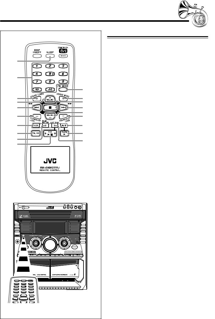
Remote Control
1

 w 2
w 2
3
MP3 |
e |
4 |
r |
|
5 |
t |
|
6 |
y |
|
7 |
u |
|
i |
||
8 |
o |
|
9 |
; |
|
p |
a |
|
q |
||
|
|
|
|
|
|
CD 1 |
CD 2 CD 3 |
|
|
|
|
|
|
|
DISC CHANGE |
|
STANDBY |
|
|
|
|
|
|
|
|
STANDBY/ON |
|
|
|
|
|
|
REC START |
R O C K |
|
|
|
|
D A N C E |
REPEAT |
/ STOP |
|
|
|
|
|||
CD REC |
P O P |
|
|
|
|
H A L L |
PROGRAM |
START |
|
|
|
|
|||
DUBBING |
CLASSIC |
|
|
|
|
STADIUM |
RANDOM |
|
|
|
|
VO |
LU |
|
CLOCK |
DISPLAY |
|
|
|
ME |
|
||
|
|
|
|
|
|
/ TIMER |
|
|
UN |
D |
MO |
DE |
|
PRESET |
SET |
|
O |
|
|
|
|
|
CANCEL / DEMO
|
TAPE A /B |
TUNING |
TUNING |
|
BEEP |
|
EJECT |
When using the remote control, point it at the remote sensor on the front panel.
Remote Control
1 BEEP ON/OFF button (11)
2 SLEEP button (25)
3 Number buttons (12, 16)
4 SOUND TURBO button (10)
5 VOLUME + button (10)
64/1(reverse search/fast rewind) button (12, 15 – 17, 19, 20)
7 SUBWOOFER LEVEL – button (10)
8AUX button (9)
Pressing this button also turns on the unit.
9FM/AM button (9, 12)
Pressing this button also turns on the unit.
p FADE MUTING button (10)
qCD 6(play/pause) button (9, 13 – 15, 18)
Pressing this button also turns on the unit.
w  STANDBY/ON button (9)
eFM MODE button (12) MP3 button (17)
r SOUND MODE button (11)
t 7(stop) button (13 – 15, 18 – 22)
y¢/¡(forward search/fast forward) button (12, 15 – 17, 19, 20)
u VOLUME – button (10)
i SUBWOOFER LEVEL + button (10) o A/B button (20)
;TAPE 3(play) button (9, 20)
Pressing this button also turns on the unit.
a DISC SKIP button (13, 15)
5
Getting Started
Continued 
Unpacking
After unpacking, check to be sure that you have all the following items.
The number in the parentheses indicates the quantity of the pieces supplied.
•AM loop antenna (1)
•FM antenna (1)
•Remote control (1)
•Batteries (2)
If any is missing, consult your dealer immediately.
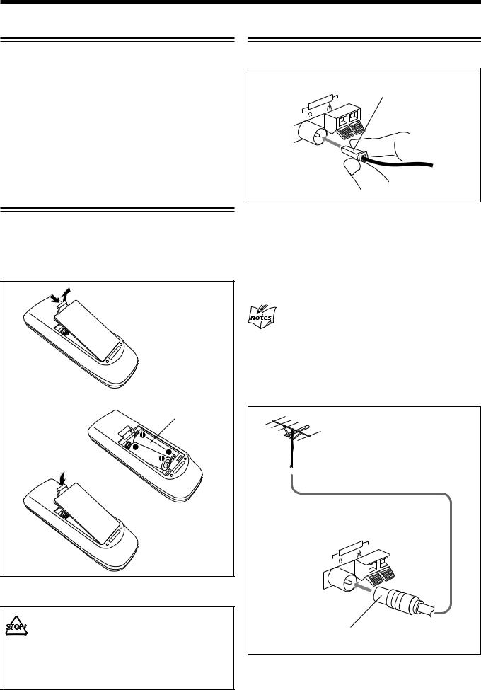
Putting the Batteries into the Remote Control
Insert the batteries—R6P(SUM-3)/AA(15F)—into the remote control, by matching the polarity (+ and –) on the batteries with the + and – markings on the battery compartment. When the remote control can no longer operate the unit, replace both batteries at the same time.
1
2 |
R6P(SUM-3)/AA(15F) |
3
• DO NOT use an old battery together with a new one.
• DO NOT use different types of batteries together.
•DO NOT expose batteries to heat or flame.
•DO NOT leave the batteries in the battery compartment when you are not going to use the remote control for an extended period of time. Otherwise, it will be damaged from battery leakage.
Connecting Antennas
FM antenna
FM antenna (supplied)
ANTENNA |
AM |
|
FM |
[75 |
] |
|
||
|
|
1Attach the FM antenna to the FM [75 Ω] coaxial terminal.
2Extend the FM antenna.
3Fasten it up in the position which gives you the best reception, then fix it on the wall, etc.
About the supplied FM antenna
The FM antenna supplied with this unit can be used as temporary measure. If reception is poor, you can connect an outdoor FM antenna.
To connect an outdoor FM antenna
Before connecting it, disconnect the supplied FM antenna.
Outdoor FM antenna (not supplied)
ANTENNA |
AM |
|
FM |
[75 |
] |
|
||
|
|
A 75 Ω antenna with coaxial type connector should be used.
6
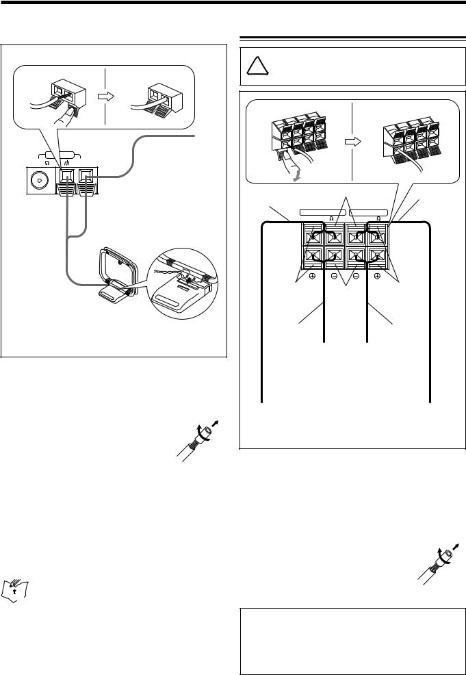
AM antenna
1 |
2, 3 |
|
wire |
|
AM loop antenna |
|
(supplied) |
1Press and hold the clamp of the AM terminal on the rear of the unit.
2Insert the end of the AM loop antenna cord
into the terminal.
• If the AM loop antenna wire is covered with vinyl, remove the vinyl by twisting it as shown in the diagram.
3Release the finger from the clamp.
4Turn the AM loop antenna until you have the best reception.
To connect an outdoor AM antenna
When reception is poor, connect a single vinyl-covered wire to the AM terminal and extend it horizontally. (The AM loop antenna must remain connected.)

 For better reception of both FM and AM
•Make sure the antenna conductors do not touch any other terminals and connecting cords.
•Keep the antennas away from metallic parts of the unit, connecting cords, and the AC power cord.
Connecting Speakers
For MX-GT88:


 DO NOT carry the speaker by holding the tube duct (on the top of the speaker).
1 |
|
2, 3 |
|
|
Speaker cord |
Black |
|
Speaker |
|
(blue/black) |
|
|
|
cord |
MAIN SPEAKER |
SUBWOOFER |
(red/black) |
||
[4-8 |
] |
[6 -16 |
] |
|
L |
|
|
L |
|
R |
|
|
R |
|
Blue |
Black |
Red |
||
|
|
|
||
Speaker cord |
|
Speaker cord |
||
(blue/black) |
|
|
(red/black) |
|
From right |
From right |
|
||
main |
|
subwoofer’s |
|
|
speaker’s |
terminals |
|
||
terminals |
|
|
|
|
From left |
|
|
|
From left |
main |
|
|
|
subwoofer’s |
speaker’s |
|
|
|
terminals |
terminals |
|
|
|
|
1Press and hold the clamp of the speaker terminal on the rear of the unit.
2Insert the end of the speaker cord into the
terminal.
Match the colors (polarity): Blue (+) to blue (+) and black
(–) to black (–); red (+) to red (+) and black (–) to black
(–).
• If the wire is covered with vinyl, remove the vinyl by twisting it as shown in the
diagram.
3 Release the finger from the clamp.
IMPORTANT:
•Use only speakers with the same speaker impedance as indicated by the speaker terminals on the rear of the unit.
•DO NOT connect more than one speaker to one speaker terminal.
7
Connecting Other Equipment
You can connect audio equipment—used only as a playback device.
• DO NOT connect any equipment while the power 

 is on.
•DO NOT plug in any equipment until all connections are complete.
To connect audio equipment
Be sure that the plugs of the audio cords are color coded: White plugs and jacks are for left audio signals, and red ones for right audio signals.
AUX IN
Audio equipment
To audio output
NOW you are ready to plug in the unit and other connected equipment.
Canceling the Display Demonstration
When connecting the AC power cord into a wall outlet, the unit automatically starts the display demonstration.
On the unit ONLY:
To cancel the display demonstration, |
CANCEL |
press CANCEL/DEMO while the display |
/ DEMO |
|
demonstration is shown on the display.
When you press other buttons
The display demonstration stops temporarily. It will start automatically again (if no operation is done for 2 minutes) until you cancel it.
To start the display demonstration manually
Press and hold CANCEL/DEMO again for |
CANCEL |
more than 2 seconds. |
/ DEMO |
|
For playing the other equipment through this unit, connect between the audio output jacks on the other equipment and AUX IN jacks by using audio cords (not supplied).
8
Common Operations
Turning On or Off the Power
To turn on the unit, press  STANDBY/ON so that the STANDBY lamp goes off.
To turn off the unit (on standby), press  STANDBY/ON again so that the STANDBY lamp lights up.
STANDBY
STANDBY/ON
STANDBY
STANDBY/ON
A little power is always consumed even while the unit is on standby.
To switch off the power supply completely, unplug the AC power cord from the AC outlet.
When you unplug the AC power cord or if a power
failure occurs
The clock is reset to “– – : – –” soon, while the tuner preset stations (see page 12) will be erased in a few days.
Setting the Clock
Before operating the unit any further, first set the clock built in this unit. You can set the clock whether the unit is on or off.
3 Turn the 4/¢control to adjust the minute, then press SET.
To check the clock time
Press DISPLAY while playing any source.
DISPLAY
• Each time you press the button, the source indication and the clock time alternate on the
display.
To adjust the clock again
If you have adjusted the clock before, you need to press CLOCK/TIMER repeatedly until “CLOCK” is selected.
•Each time you press the button, the clock/timer setting modes change as follows:
 DAILY
DAILY  ON TIME
  REC
REC
(Daily Timer)
Canceled  CLOCK
CLOCK  ON TIME
(Recording Timer)
If there is a power failure
The clock loses the setting and is reset to “– – : – –.” You need to set the clock again.
On the unit ONLY: |
|
1 Press CLOCK/TIMER. |
/ TIMER |
|
CLOCK |
The hour digits start flashing on the display.
2 Turn the 4/¢control to adjust the hour, then press SET.
The minute digits start flashing on the display.
•If you want to correct the hour after pressing SET, press CANCEL/DEMO. The hour digits start flashing again.
Selecting the Sources
To listen to the radio, press FM/AM. (See page 12.) To play back CDs, press CD 6. (See pages 13 – 19.) To play back tapes, press TAPE 3. (See page 20.)
To select the external equipment as the source, press AUX.
When you press the play button for a particular source (AUX, FM/AM, CD 6, and TAPE 3), the unit turns on (and the unit starts playing the source if it is ready—COMPU PLAY CONTROL).
9
Continued 
Adjusting the Volume
You can adjust the volume level only while the unit is turned on.
This function only affects the playback sound, not your recording.
Turn the VOLUME control |
VO |
LU |
ME |
|
|||
|
|
clockwise to increase the volume or counterclockwise to decrease it.
•The volume level can be adjusted in 32 steps (VOL MIN, VOL 1 — VOL 30, and VOL MAX).
When using the remote control, press VOLUME + to increase the volume or press VOLUME – to decrease it.
For private listening
Connect a pair of headphones to the PHONES jack. No sound comes out of the speakers. Be sure to turn down the volume before connecting or putting on headphones.
DO NOT turn off (on standby) the unit with the volume set to an extremely high level; otherwise, a sudden blast of sound can damage your hearing, speakers and/or headphones when you turn on the unit or start playing any source next time. REMEMBER you cannot adjust the volume level while the unit is on standby.
To turn down the volume level temporarily
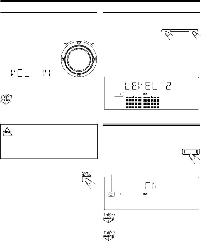
Press FADE MUTING on the remote control. The volume level gradually decreases to “VOL MIN.”
To restore the sound, press the button again.
Reinforcing the Bass Sound
This function only affects the playback sound, not your recording.
Press SUBWOOFER LEVEL + to 
 SUBWOOFER LEVEL
 increase the subwoofer sound or
SUBWOOFER LEVEL – to decrease it.
•The subwoofer level can be adjusted in 3 steps (LEVEL 1 — LEVEL 3).
If you press SUBWOOFER LEVEL + to increase the level up to LEVEL 3, “MAX LEVEL” appears on the display.
WOOFER indicator also shows the current subwoofer level.
WOOFER 
Enjoying the Heavy Sound
You can enjoy the heavy sound by using the sound turbo. The function boosts the low and high frequency sound.
This function only affects the playback sound, not your recording.
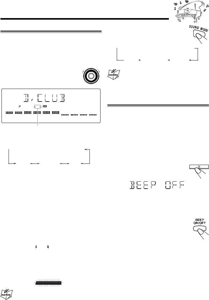
Press SOUND TURBO. |
SOUND |
The TURBO indicator lights up on the display. |
|
•Each time you press SOUND TURBO, the sound turbo turns on and off alternately.
TURBO indicator
TURBO WOOFER 
When you turn off the sound turbo
The subwoofer level is set to LEVEL 1.
When the sound turbo is on
Turning the SOUND MODE control (or pressing SOUND MODE on the remote control) cancels the sound turbo.
10
Selecting the Sound Modes
This function only affects the playback sound, not your recording.
You can select one of the 6 preset sound modes (3 surround modes and 3 SEA—Sound Effect Amplifier—modes).
To select the sound modes, turn the |
D |
MO |
|
UN |
D |
||
O |
|
||
|
S |
|
E |
SOUND MODE control until the sound |
|
|
|
mode you want appears on the display. |
|
|
|
When using the remote control, press
SOUND MODE to select the sound mode.
•Each time you press the button, the sound modes change as follows:
 D.CLUB
  HALL
HALL  STADIUM
  ROCK
ROCK
(Dance CLUB)
OFF |
|
CLASSIC |
|
POP |
(Canceled) |
|
|
||
|
|
|
|
When the sound mode is activated
Pressing SOUND TURBO cancels the sound mode (set to OFF).
WOOFER |
SOUND |
|
MODE |
SOUND MODE indicator also lights up on the display
•As you turn the control, the sound modes change as follows:
 D.CLUB
 HALL
HALL
 STADIUM
 ROCK
ROCK
(Dance CLUB)
OFF CLASSIC POP
(Canceled)
Surround modes*:
D.CLUB : Increases resonance and bass.
HALL : Adds depth and brilliance to the sound. STADIUM: Adds clarity and spreads the sound, like in an
outdoor stadium.
SEA (Sound Effect Amplifier) modes:
ROCK : Boosts low and high frequency. Good for acoustic music.
POP : Good for vocal music. CLASSIC : Good for classical music.
OFF : Cancels the sound mode.
*Surround elements are added to the SEA elements to create being-there feeling in your room.
When one of these modes is selected, the SOUND MODE
indicator lights up as  SOUND
SOUND .
.
MODE
While one of the SEA modes (SEA elements without surround elements) is selected, the SOUND MODE indicator lights up
as SOUNDMODE .
• The corresponding sound mode lamp also flashes.
D A N C E
When the sound mode is set to OFF
All sound mode indicators do not flash but light up.
Turning On or Off the Key-touch Tone
If you do not want the key-touch tone to beep each time you press a button or turn a control, you can deactivate it.
•You can turn on or off the key-touch tone as follows: –When the unit is off:
You can turn on or off the key-touch tone by operating the unit.
–When the unit is on:
You can turn on or off the key-touch tone by operating the unit or the remote control.
On the unit:
Press and hold BEEP for more than 2
BEEP
seconds.
•Each time you press and hold the button, the key-touch tone turns on and off alternately.
On the remote control:
Press BEEP ON/OFF when the unit is on.
•Each time you press the button, the key-touch tone turns on and off alternately.
11
Loading...