


 Loading...
AUDIO/VIDEO CONTROL RECEIVER
RX-7012VSL
CATV/DBS |
VCR |
TV |
AUDIO |
DVD |
DVD MUILTI |
CD |
FM/AM |
TV/DBS |
VCR |
TAPE/CDR |
PHONO |
− BASS + |
−TREBLE + |
||
SURROUND |
DSP ANALOG/DIGITAL |
SLEEP |
|
ON/OFF |
MODE |
INPUT |
|
BASSBOOST |
EFFECT |
+ CENTER – |
|
|
1 |
2 |
3 |
|
|
MENU |
|
|
TEST |
+ REAR•L – |
|
|
4 |
5 |
6 |
|
|
ENTER |
|
SOUND |
|
– REAR•R + |
|
|
7/P |
8 |
9 |
MUTING |
|
–SUBWOOFER+ |
|
|
10 |
0 |
+10 |
|
RETURN |
FMMODE |
100+ |
CATV/DBS |
|
|
|
CONTROL |
+ |
+ |
+ |
|
|||
TV/VIDEO |
CH |
TV VOL |
VOLUME |
− |
− |
− |
|
+ |
|
PLAY |
|
|
|
|
|
TUNING |
/REW |
PAUSE |
FF/ |
− |
|
|
|
REC |
|
|
|
PAUSE |
|
|
|
|
|
STOP |
CONTROL |
RM-SRX7012U
A/V CONTROL RECEIVER
|
|
RX-7012V AUDIO/VIDEO CONTROL RECEIVER |
|
FM/AM TUNING |
FM/AM PRESET |
FM MODE |
|
|
|
|
COMPULINK |
STANDBY |
|
MASTER VOLUME |
Remote |
|
|
|
|
|
|
MEMORY |
|
STANDBY/ON
D I G I T A L
SURROUND ON/OFF |
INPUT |
|
|
|
|
|
|
ANALOG/DIGITAL |
BASS BOOST |
|
|
|
ADJUST |
SETTING |
|
|
|
|
DVD MULTI |
DVD |
VCR |
TV SOUND/DBS |
|
|
INPUT ATT |
|
|
|
|
|
|
|
|
|
|
|
|
SOURCE NAME |
|
DSP MODE |
|
|
|
|
|
CONTROL |
|
SPEAKERS ON/OFF |
|
|
|
DOWN |
UP |
||
|
1 |
2 |
PHONO |
CD |
TAPE/CDR |
FM/AM |
|
SOURCE NAME
PHONES
D I G I T A L
INSTRUCTIONS
For Customer Use:
Enter below the Model No. and Serial No. which are located either on the rear, bottom or side of the cabinet. Retain this information for future reference.
Model No.
Serial No.
LVT0579-007A
[A]
Warnings, Cautions and Others
Caution ––
 switch!
Disconnect the mains plug to shut the power off completely. The  switch in any position does not disconnect the mains line. The power can be remote controlled.
CAUTION
To reduce the risk of electrical shocks, fire, etc.:
1.Do not remove screws, covers or cabinet.
2.Do not expose this appliance to rain or moisture.
CAUTION
•Do not block the ventilation openings or holes.
(If the ventilation openings or holes are blocked by a newspaper or cloth, etc., the heat may not be able to get out.)
•Do not place any naked flame sources, such as lighted candles, on the apparatus.
•When discarding batteries, environmental problems must be considered and local rules or laws governing the disposal of these batteries must be followed strictly.
•Do not use this apparatus in a bathroom or places with water. Also do not place any containers filled with water or liquids (such as cosmetics or medicines, flower vases, potted plants, cups, etc.) on top of this apparatus.
G-1
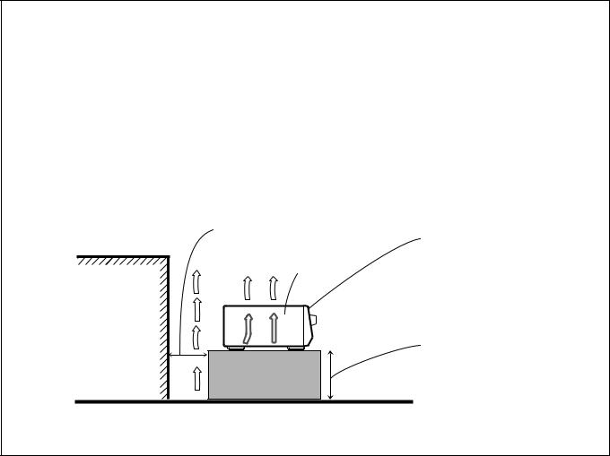
Caution: Proper Ventilation
To avoid risk of electric shock and fire and to protect from damage. Locate the apparatus as follows:
Front: |
No obstructions open spacing. |
Sides: |
No obstructions in 10 cm from the sides. |
Top: |
No obstructions in 10 cm from the top. |
Back: |
No obstructions in 15 cm from the back |
Bottom: |
No obstructions, place on the level surface. |
In addition, maintain the best possible air circulation as illustrated.
Spacing 15 cm or more
Front
Wall or obstructions |
RX-7012VSL
Stand height 15 cm or more
Floor
G-2

Table of Contents |
|
Parts Identification ...................................... |
2 |
Getting Started........................................... |
3 |
Before Installation ...................................................................... |
3 |
Checking the Supplied Accessories ........................................... |
3 |
Connecting the FM and AM Antennas ....................................... |
3 |
Connecting the Speakers ............................................................ |
4 |
Connecting Audio/Video Components ....................................... |
5 |
Connecting the Power Cord ....................................................... |
9 |
Putting Batteries in the Remote Control .................................... |
9 |
Basic Operations ....................................... |
10 |
Turning the Power On and Off (Standby) ................................ |
10 |
Selecting the Source to Play ..................................................... |
10 |
Adjusting the Volume ............................................................... |
11 |
Selecting the Front Speakers .................................................... |
11 |
Muting the Sound ..................................................................... |
12 |
Reinforcing the Bass ................................................................ |
12 |
Adjusting the Tone ................................................................... |
12 |
Attenuating the Input Signal .................................................... |
12 |
Adjusting the Subwoofer Output Level .................................... |
12 |
Basic Settings........................................... |
13 |
Recording a Source .................................................................. |
13 |
Adjusting the Front Speaker Output Balance ........................... |
13 |
Changing the Source Name ...................................................... |
13 |
Setting the Subwoofer Information .......................................... |
14 |
Setting the Speakers for the DSP Modes ................................. |
14 |
Digital Input (DIGITAL IN) Terminal Setting ......................... |
16 |
Selecting the Analog or Digital Input Mode ............................ |
16 |
Storing the Basic Settings and Adjustments ............................. |
17 |
Using the Sleep Timer .............................................................. |
17 |
Receiving Radio Broadcasts ........................ |
18 |
Tuning in Stations Manually .................................................... |
18 |
Using Preset Tuning ................................................................. |
18 |
Selecting the FM Reception Mode ........................................... |
19 |
Using the DSP Modes ................................ |
20 |
What are the DSP Modes? ........................................................ |
20 |
Reproducing the Sound Field .................................................... |
21 |
Available DSP Modes According to the Speaker Arrangement .. |
22 |
Adjusting the Surround Modes ................................................ |
23 |
Adjusting the DAP Modes ....................................................... |
25 |
Activating the DSP Modes ....................................................... |
26 |
Using the DVD MULTI Playback Mode .......... |
27 |
Activating the DVD MULTI Playback Mode .......................... |
27 |
COMPU LINK Remote Control System ......... |
28 |
AV COMPU LINK Remote Control System .... |
29 |
Operating JVC’s Audio/Video Components ... |
31 |
Operating Audio Components .................................................. |
31 |
Operating Video Components .................................................. |
33 |
Operating Other Manufacturers’ Video |
|
Equipment ............................................ |
34 |
Troubleshooting ......................................... |
38 |
Specifications............................................ |
39 |
1
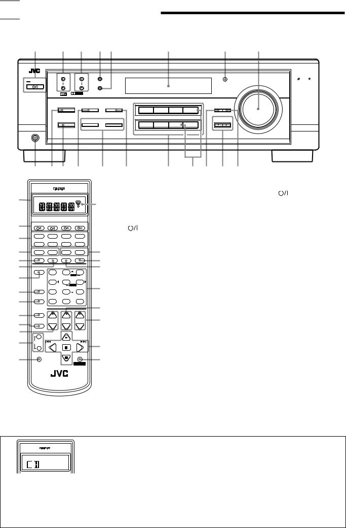

 Parts Identification
Become familiar with the buttons and controls on the receiver before use.
Refer to the pages in parentheses for details.
1 |
2 |
|
3 |
4 5 |
|
|
6 |
|
7 |
8 |
|
|
|
|
|
|
|
RX-7012V AUDIO/VIDEO CONTROL RECEIVER |
|
|
|||
|
FM/AM TUNING |
|
FM/AM PRESET |
FM MODE |
|
|
|
|
|
|
COMPULINK |
|
|
|
|
|
|
|
|
|
|
|
|
|
|
|
|
|
|
|
|
|
|
|
Remote |
STANDBY |
|
|
|
|
|
|
|
|
|
|
MASTER VOLUME |
|
|
|
|
MEMORY |
|
|
|
|
|
|
|
|
|
|
|
|
|
|
|
|
|
|
|
STANDBY/ON |
|
|
|
|
|
|
|
|
|
|
|
|
D I G I T A L |
|
|
|
|
|
|
|
|
|
|
|
S U R R O U N D |
D I G I T A L |
|
|
|
|
|
|
|
|
|
|
SURROUND ON/OFF |
INPUT |
|
|
|
|
|
|
|
|
|
|
ANALOG/DIGITAL |
BASS BOOST |
|
|
|
ADJUST SETTING |
|
||||
|
|
|
|
|
|
|
|||||
|
|
|
|
|
|
DVD MULTI |
DVD |
VCR |
TV SOUND/DBS |
|
|
|
|
|
INPUT ATT |
|
|
|
|
|
|
|
|
|
|
|
|
|
|
|
|
|
SOURCE NAME |
|
|
|
DSP MODE |
|
|
|
|
|
|
|
CONTROL |
|
|
|
|
|
SPEAKERS ON/OFF |
|
|
|
DOWN |
UP |
|
||
|
|
|
1 |
|
2 |
PHONO |
CD |
TAPE/CDR |
FM/AM |
|
|
|
|
|
|
|
|
|
|
SOURCE NAME |
|
|
|
PHONES |
|
|
|
|
|
|
|
|
|
|
|
9 p q w e r |
|
|
t y u i o |
||||||||
|
|
|
|
|
Remote Control |
|
|
Front Panel |
|||
1 a
2 |
CATV/DBS |
VCR |
TV |
AUDIO |
|
|
DVD DVD MUILTI |
CD |
FM/AM |
||
3 |
TV/DBS |
VCR |
TAPE/CDR |
PHONO |
|
4 |
− BASS |
+ |
−TREBLE+ |
||
5 |
SURROUND |
DSP ANALOG/DIGITAL |
SLEEP |
||
ON/OFF |
MODE |
INPUT |
|
||
6 |
BASSBOOST |
EFFECT |
– CENTER+ |
||
7 |
|
1 |
2 |
3 |
|
|
|
MENU |
|||
|
TEST |
– REAR• L+ |
|||
|
|
4 |
5 |
6 |
|
|
|
|
ENTER |
||
8 |
SOUND |
|
– REAR• R+ |
||
|
7/P |
8 |
9 |
||
9 |
MUTING |
|
–SUBWOOFER+ |
||
|
10 |
0 |
+10 |
||
|
|
RETURN |
FMMODE |
100+ |
|
|
CATV/DBS |
+ |
+ |
+ |
|
p |
CONTROL |
||||
|
|||||
q |
|
CH |
TV VOL |
VOLUME |
|
TV/VIDEO |
− |
− |
− |
||
w |
+ |
|
PLAY |
|
|
e |
/REW |
PAUSE |
FF/ |
||
TUNING |
|||||
|
− |
|
|
|
|
|
REC |
|
|
|
|
r |
PAUSE |
|
|
|
|
|
|
STOP |
CONTROL |
||
|
|
|
|||
RM-SRX7012U
A/V CONTROL RECEIVER
|
1 |
Display window (See below) * |
1 |
STANDBY/ON |
|
|
button and STANDBY |
||
|
|
||||||||
b |
|
a: Remote control operation mode indicator |
|
lamp (10) |
|
||||
|
b: Signal transmission indicator |
2 |
FM/AM TUNING 5/ buttons (18) |
||||||
|
|
||||||||
|
|
|
Lights up when transmitting the remote |
3 |
FM/AM PRESET 5/ buttons (18) |
||||
|
|
|
control signal. |
4 |
FM MODE button (19) |
||||
|
2 |
|
buttons (10, 33 – 37) |
5 |
MEMORY button (18) |
||||
|
|
||||||||
|
|
CATV/DBS, VCR, TV, AUDIO |
6 |
Display (10) |
|
||||
|
3 |
Source selecting buttons (10, 17) * |
7 |
Remote sensor (9) |
|
||||
t |
|
DVD, DVD MULTI, CD, FM/AM,TV/DBS,VCR, |
8 |
MASTER VOLUME control (11) |
|||||
y |
|
TAPE/CDR, PHONO |
9 |
PHONES jack (11) |
|
||||
4 BASS +/– buttons (12) |
p SURROUND ON/OFF button (22, 23, 26) |
||||||||
u |
|||||||||
|
5 |
SURROUND ON/OFF button (22, 23, 26) |
q DSP MODE button (24 – 26) |
||||||
|
6 |
DSP MODE button (24 – 26) |
w INPUT ANALOG/DIGITAL button (17) |
||||||
i |
7 |
BASS BOOST button (12) |
|
INPUT ATT button (12) |
|||||
8 SOUND button (12, 23 – 25, 27) * |
e SPEAKERS ON/OFF 1 button (11) |
||||||||
|
9 |
MUTING button (12) |
|
SPEAKERS ON/OFF 2 button (11) |
|||||
o |
p CATV/DBS CONTROL button (35) * |
r BASS BOOST button (12) |
|||||||
q TV/VIDEO button (33, 34) |
t Source selecting buttons (10, 16) |
||||||||
; |
w CH(annel) +/– buttons (33 – 36) |
|
DVD MULTI, DVD, VCR, TV SOUND/DBS, |
||||||
|
e TUNING +/– buttons (18) |
|
PHONO, CD, TAPE/CDR, FM/AM |
||||||
|
r REC PAUSE button (32, 33, 36) |
y SOURCE NAME buttons (13) |
|||||||
a |
t TREBLE +/– buttons (12) |
|
• The TV SOUND/DBS button and TAPE/CDR |
||||||
y SLEEP button (17) |
|
button also function as the SOURCE NAME |
|||||||
s |
u ANALOG/DIGITAL INPUT button (17) |
|
button. |
|
|||||
i • 10 keys for selecting preset channels (19) |
u ADJUST button (12, 13, 23 – 25, 27) |
||||||||
|
|
• 10 keys for adjusting sound (12, 19, 23 – 25, 27) |
i CONTROL UP 5/DOWN buttons |
||||||
|
|
• 10 keys for operating audio/video components |
o SETTING button (14 – 16) |
||||||
|
|
(31 – 37) |
|
|
|
|
|
||
|
o TV VOL(ume) +/– buttons (33, 34) |
|
|
|
|
|
|||
; VOLUME +/– buttons (11)
a Operating buttons for audio/video components (31 – 33, 36, 37)
s CONTROL button (32, 33) *
*When you press one of these buttons, the remote control operation mode appears on the display window for about 10 seconds.
Ex.: When you press CD button
Buttons on the Remote Control |
Remote Control Operation Mode |
|
|
FM/AM |
TUNER |
CD |
CD |
PHONO |
PHONO |
TAPE/CDR |
TAPE |
DVD |
DVD |
DVD MULTI |
DVD |
Buttons on the Remote Control |
Remote Control Operation Mode |
TV/DBS |
TV |
VCR |
VCR |
CATV/DBS CONTROL |
DBS |
CONTROL |
Current setting or VCR or TAPE |
|
or CDDSC |
|
|
SOUND |
SOUND |
2


 Getting Started
This section explains how to connect audio/video components and speakers to the receiver, and how to connect the power supply.
Before Installation
General
•Be sure your hands are dry.
•Turn the power off to all components.
•Read the manuals supplied with the components you are going to connect.
Locations
•Install the receiver in a location that is level and protected from moisture.
•The temperature around the receiver must be between –5˚C and 35˚C (23˚F and 95˚F).
•Make sure there is good ventilation around the receiver. Poor ventilation could cause overheating and damage the receiver.
Handling the receiver
•Do not insert any metal object into the receiver.
•Do not disassemble the receiver or remove screws, covers, or cabinet.
•Do not expose the receiver to rain or moisture.
Checking the Supplied Accessories
Check to be sure you have all of the following items, which are supplied with the receiver.
The number in the parentheses indicates quantity of the pieces supplied.
•Remote Control (1)
•Batteries (2)
•AM Loop Antenna (1)
•FM Antenna (1)
If anything is missing, contact your dealer immediately.
Connecting the FM and AM Antennas
FM Antenna Connections
A |
ANTENNA |
75 |
B |
ANTENNA |
75 |
|
|
FM |
|
|
FM |
|
|
COAXIAL |
|
|
COAXIAL |
|
AM |
AM |
|
AM |
AM |
|
EXT |
|
EXT |
||
|
LOOP |
|
LOOP |
||
|
|
|
|
||
|
|
|
FM Antenna |
|
|
ANTENNA |
|
Extend the supplied FM antenna horizontally. |
|||
|
FM 75 |
|
|
|
|
|
COAXIAL |
|
|
|
|
AM |
Outdoor FM Antenna Cable |
LOOP |
AM
EXT
A.Using the Supplied FM Antenna
The FM antenna provided can be connected to the FM 75 Ω COAXIAL terminal as temporary measure.
B.Using the Standard Type Connector (Not Supplied)
A standard type connector (IEC or DIN45325) should be connected to the FM 75 Ω COAXIAL terminal.
Note:
If reception is poor, connect the outdoor antenna.
Before attaching a 75 Ω coaxial cable (the kind with a round wire going to an outdoor antenna), disconnect the supplied FM antenna.
3
AM Antenna Connections
|
|
|
|
Snap the tabs on the loop into the |
|
|
slots of the base to assemble the |
||
ANTENNA |
||||
|
|
FM 75 |
AM loop. |
|
|
|
COAXIAL |
|
|
|
|
|
|
|
AM
LOOP
AM |
|
AM Loop Antenna |
EXT |
|
|
1 |
2 |
3 |
Outdoor single vinyl-covered wire (not supplied)
Turn the loop until you have the best reception.
Notes:
• If the AM loop antenna wire is covered with vinyl, remove the vinyl by twisting it as shown in the diagram.
• Make sure the antenna conductors do not touch any other terminals, connecting cords and power cord. This could cause poor reception.
•If reception is poor, connect an outdoor single vinyl-covered wire to the AM EXT terminal. (Keep the AM loop antenna connected.)
Basic connecting procedure
1 |
2 |
3 |
4 |
|
1 |
|
1 |
|
RIGHT |
|
RIGHT |
1
RIGHT
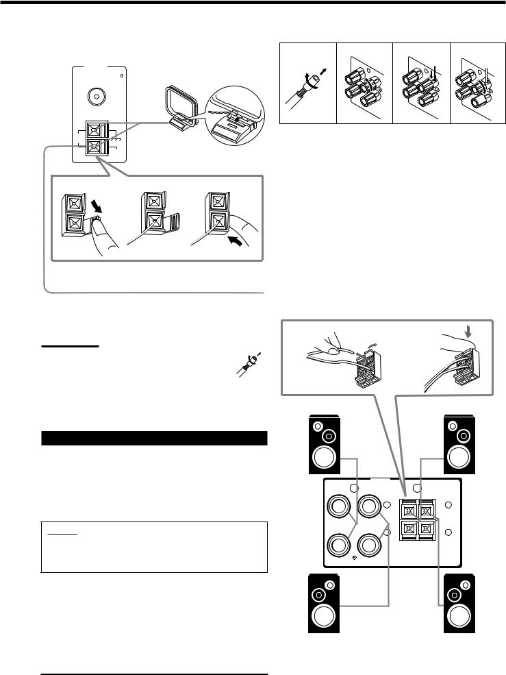
1Cut, twist and remove the insulation at the end of each speaker signal cable (not supplied).
2Turn the knob counterclockwise.
3Insert the speaker signal cable.
4Turn the knob clockwise.
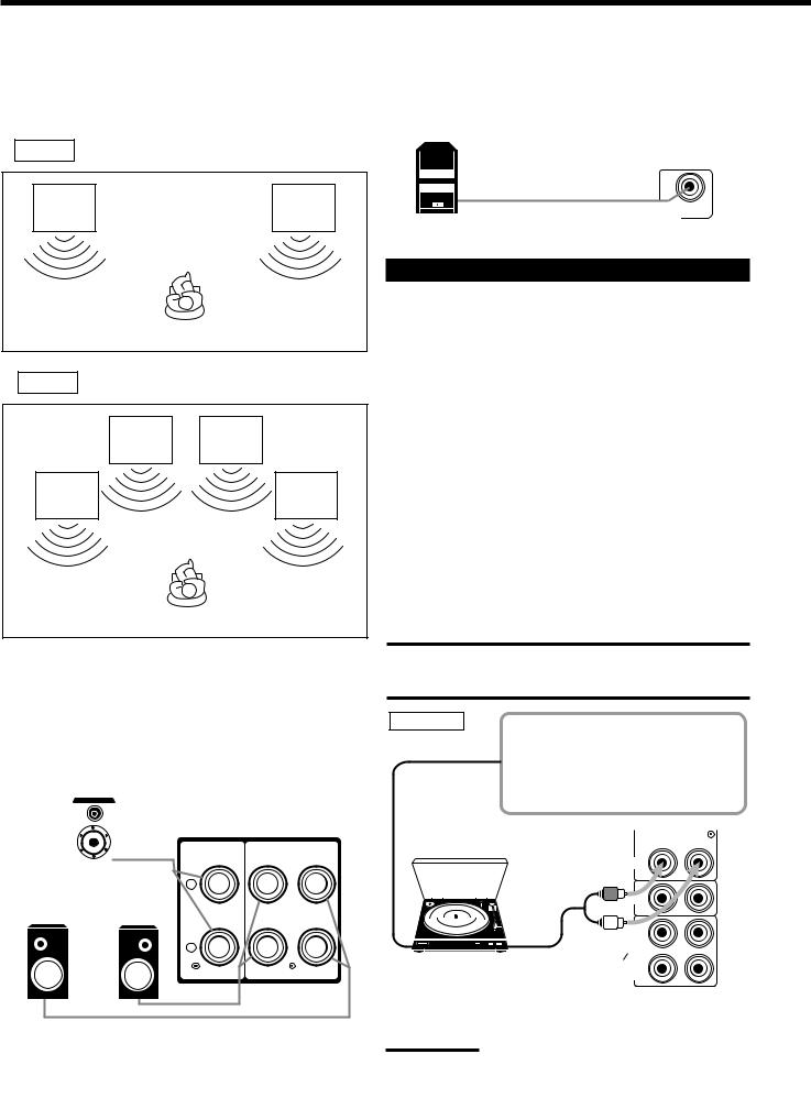
Connecting the front speakers
You can connect two pairs of front speakers (one pair to the FRONT SPEAKERS 1 terminals, and another pair to the FRONT SPEAKERS 2 terminals).
1 |
2 |
Right speaker |
Right speaker |
Connecting the Speakers
You can connect the following speakers:
•Two pairs of front speakers to produce normal stereo sound.
•One pair of rear speakers to enjoy the surround effect.
•One center speaker to produce more effective surround effect (to emphasize human voices).
•One subwoofer to enhance the bass.
IMPORTANT:
After connecting the speakers listed above, set the speaker setting information properly to obtain the best possible DSP effect. For details, see page 14.
For each speaker (except for a subwoofer), connect the (+) and (–) terminals on the rear panel to the (+) and (–) terminals marked on the speakers. For connecting a subwoofer, see page 5.
1 |
FRONT |
2 |
|
SPEAKERS |
|
||
FRONT |
+ |
+ |
FRONT |
|
|
||
SPEAKERS |
– |
– |
SPEAKERS |
1 |
2 |
||
|
RIGHT |
LEFT |
|
RIGHT |
LEFT |
|
|
CAUTION: |
Left speaker |
Left speaker |
|
|
Use speakers with the SPEAKER IMPEDANCE indicated by the speaker terminals.
4
About the speaker impedance
The required speaker impedance of the front speakers does differ depending on whether both the FRONT SPEAKERS 1 and FRONT SPEAKERS 2 terminals are used or only one of them is used.
CASE 1 When you connect only one pair of front speakers
Front |
Front |
speaker |
speaker |
1 |
1 |
Use front speakers with 8 Ω – 16Ω impedance.
CASE 2 When you connect two pairs of front speakers
Front |
Front |
speaker |
speaker |
2 |
2 |
Front |
Front |
speaker |
speaker |
1 |
1 |
Use front speakers 16 Ω – 32Ω impedance.
Connecting the rear and center speakers
Connect rear speakers to the REAR SPEAKERS terminals and a center speaker to the CENTER SPEAKER terminals.
Center speaker
|
|
|
|
|
|
|
|
CENTER |
|
REAR |
|
|
|
|
|
SPEAKERS |
|
|
|
SPEAKER |
+
Left rear |
Right rear |
speaker |
speaker |
–
RIGHT LEFT
Connecting the subwoofer speaker
You can enhance the bass by connecting a subwoofer. Connect the input jack of a powered subwoofer to the
SUBWOOFER OUT jack on the rear panel, using a cable with RCA pin plugs (not supplied).
SUBWOOFER
OUT
Powered subwoofer
Connecting Audio/Video Components
You can connect the following audio/video components to this receiver. Refer also to the manuals supplied with your components.
Audio Components |
Video Components |
|
|
• Turntable |
• DVD player* |
|
|
• CD player* |
• TV* |
• Cassette deck |
• DBS tuner* |
or CD recorder* |
• VCR |
|
|
*You can connect these components using the methods described in
“Analog connections” (below) or in “Digital connections” (see page
8).
Analog connections
Audio component connections
Use the cables with RCA pin plugs (not supplied).
Connect the white plug to the audio left jack, and the red plug to the audio right jack.
CAUTION:
If you connect a sound-enhancing device such as a graphic equalizer between the source components and this receiver, the sound output through this receiver may be distorted.
Turntable
If an earth cable is provided for your turntable, connect the cable to the AM (H) terminal on the rear panel.
Turntable
|
PHONO |
|
CD |
To audio |
|
output |
OUT |
|
(REC) |
|
TAPE |
Ex.: This connection is for the |
CDR |
IN |
|
turntable with an MM (moving- |
(PLAY) |
|
|
magnet) type cartridge. |
OUT |
|
(REC) |
|
VCR |
Note: |
IN |
(PLAY) |
Any turntables incorporating a small-output cartridge such as an MC
TV
(moving-coil) type must be connected to this SOUNDreceiver through a
DBS
commercial head amplifier or step-up transformer. Direct connection
RIGHT LEFT
may result in insufficient volume. |
AUDIO |
|
5
CD player
PHONO
CD player
|
CD |
|
OUT |
|
(REC) |
To audio output |
TAPE |
CDR |
|
|
IN |
|
(PLAY) |
|
OUT |
|
(REC) |
|
VCR |
Cassette deck or CD recorder
|
Cassette deck |
To audio input |
To audio output |
|
PHONO
CD
OUT (REC)
TAPE
CDR
IN (PLAY)
OUT (REC)
VCR
IN (PLAY)
TV
SOUND
DBS
RIGHT LEFT
AUDIO
To audio input |
|
|
|
|
To audio output |
|
|
|
|
||
|
|
|
|
||
|
|
CD recorder |
|||
Note:
You can connect either a cassette deck or a CD recorder to the TAPE/
CDR jacks. When connecting a CD recorder to the TAPE/CDR jacks, change the source name, which will be shown on the display when selected as the source, to “CDR.” See page 13 for details.
If your audio components have a COMPU LINK jack
See also page 28 for detailed information about the connection and the COMPU LINK remote control system.
Video component connections
Use the cables with RCA pin plugs (not supplied).
Connect the white plug to the audio left jack, the red plug to the audio right jack, and the yellow plug to the video jack.
If your video components have S-video (Y/C-separation) terminals, connect them using S-video cables (not supplied). Connecting these video components through the S-video input/output terminals will give you better picture playback (or recording) quality.
IMPORTANT:
This receiver is equipped with both the composite video and S-video input/output terminals for connecting video components.
You do not have to connect both the composite video and S-video terminals.
However, remember that the video signals from the composite video input terminals are output only through the composite video output terminals, while the ones from the S-video input terminals are output only through the S-video output terminals.
Therefore, if a recording video component and a playing video component are connected to the receiver through the different video terminals, you cannot record the picture from the playing component on the recording component. In addition, if the TV and a playing video component are connected to the receiver through the different video terminals, you cannot view the playback picture from the playing component on the TV.
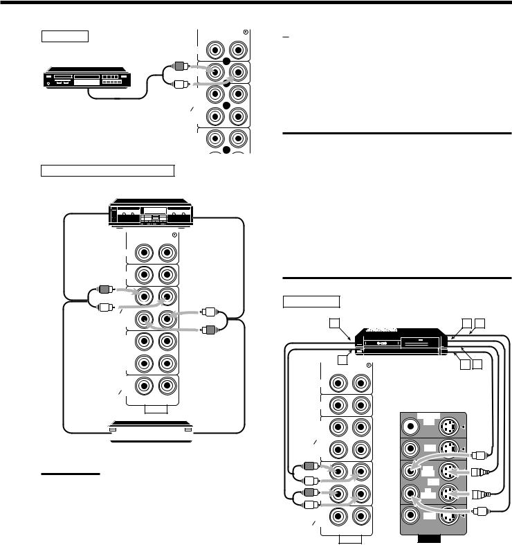
VCR
A |
|
S-VHS (or VHS) VCR |
C |
D |
|
|
|||
|
B |
|
E |
F |
|
|
|
PHONO
CD
MONITOR
OUT  OUT (REC)
TAPE |
|
|
CDR |
|
DVD |
IN |
|
|
(PLAY) |
|
|
OUT |
|
OUT |
(REC) |
|
(REC) |
VCR |
|
VCR |
IN |
|
IN |
(PLAY) |
|
(PLAY) |
TV |
|
DBS |
SOUND |
|
|
DBS |
|
|
RIGHT |
LEFT |
|
AUDIO |
VIDEO |
|
Å To left/right channel audio output ı To left/right channel audio input Ç To S-video output
Î To composite video output ‰ To composite video input Ï To S-video input
6

TV and/or DBS tuner
To S-video input
To composite video input
PHONO |
|
|
Connect the TV to the MONITOR |
|
|
OUT jack to view the playback |
|
|
CD |
|
|
picture from the other connected |
MONITOR |
|
video components. |
||
OUT |
||
OUT |
||
(REC) |
|
|
TAPE |
|
|
CDR |
DVD |
|
IN |
||
(PLAY) |
|
OUT |
OUT |
(REC) |
(REC) |
VCR |
VCR |
IN |
IN |
(PLAY) |
(PLAY) |
TV
 TV
TV
|
SOUND |
DBS |
To audio |
DBS |
|
RIGHT LEFT |
|
|
output |
|
|
AUDIO |
VIDEO |
When connecting the TV to the AUDIO jacks (TV SOUND/DBS), DO NOT connect the TV’s video output to these video input terminals.
DVD player
• When you connect the DVD player with stereo output jacks:
A |
DVD player |
B C |
DVD |
MONITOR
OUT
AUDIO
RIGHT |
LEFT |
|
FRONT |
|
DVD |
|
DVD |
|
CENTER |
|
OUT |
SUB |
(REC) |
|
|
VCR |
|
REAR |
WOOFER |
|
|
IN |
|
|
|
|
|
|
(PLAY) |
RIGHT |
LEFT |
|
|
|
DBS |
SUBWOOFER |
|
|
OUT |
|
VIDEO |
|
|
Å To front left/right channel audio output (or to audio mixed output if necessary)
ı To S-video output
Ç To composite video output
• When you connect the DVD player with its analog discrete output (5.1 CH reproduction) jacks:
Note:
When using AV COMPU LINK remote control system, you can only connect the TV with AV COMPU LINK EX to the AV COMPU LINK terminal. See page 29 for details.
A |
E |
DVD player |
C |
DVD |
B
D |
F |
|
VCR |
|
VCR |
|
IN |
|
IN |
|
(PLAY) |
|
(PLAY) |
|
TV |
|
DBS |
|
SOUND |
|
|
To audio |
DBS |
|
|
|
RIGHT LEFT |
|
|
output |
DBS tuner |
AUDIO |
VIDEO |
|
|
|
|
|
DBS |
|
|
To composite video output
To S-video output
Note:
When connecting the DBS tuner to the TV SOUND/DBS jacks, change the source name, which will be shown on the display when selected as the source, to “DBS.” See page 13 for details.
MONITOR
OUT
AUDIO
RIGHT |
LEFT |
|
FRONT |
|
DVD |
|
DVD |
|
CENTER |
|
OUT |
SUB |
(REC) |
|
|
VCR |
|
REAR |
WOOFER |
|
|
IN |
|
|
|
|
|
|
(PLAY) |
RIGHT |
LEFT |
|
|
|
DBS |
SUBWOOFER |
|
|
OUT |
|
VIDEO |
|
|
Å To center channel audio output ı To subwoofer audio output
Ç To S-video output
Î To front left/right channel audio output ‰ To rear left/right channel audio output Ï To composite video output
7
Digital connections
This receiver is equipped with four DIGITAL IN terminals — one digital coaxial terminal and three digital optical terminals, and one DIGITAL OUT terminal.
You can connect any digital equipment such as —
•DBS tuner,
•Digital TV broadcast tuner,
•DVD player,
•CD player, and
•CD recorder.
IMPORTANT:
•When connecting the DVD player, digital TV broadcast tuner or DBS tuner using the digital terminals, you also need to connect it to the video jack (either composite video terminal or S-video terminal) on the rear. Without connecting it to the video jack, you can view no playback picture.
•After connecting the components using the DIGITAL IN terminals, set the following correctly if necessary.
–Set the digital input (DIGITAL IN) terminal setting correctly. For details, see “Digital Input (DIGITAL IN) Terminal Setting” on page 16.
–Select the digital input mode correctly. For details, see “Selecting the Analog or Digital Input Mode” on page 16.
Digital input terminals
Digital TV
DVD player
DVD |
|
|
|
|
|
|
|
|
|
|
|
|
|
|
CD player |
|
CD recorder |
|||||||||
|
|
|
|
|
|
|
|
|
|
|
|
|
|
|
|
|
|
|
|
|
|
|
|
|
|
|
|
|
|
|
|
|
|
|
|
|
|
|
Digital coaxial cable (not supplied) between digital coaxial terminals
Digital optical cable (not supplied) between digital optical terminals
When the component has a digital coaxial output terminal, connect it to the DIGITAL 1 (DVD) terminal, using the digital coaxial cable (not supplied).
When the component has a digital optical output terminal, connect it to the DIGITAL 2 (CD), DIGITAL 3 (TV), or DIGITAL 4 (CDR) terminal, using the digital optical cable (not supplied).
Before connecting a digital optical cable, unplug the protective plug. 
DIGITAL 1 (DVD)
DIGITAL 2 ( CD )
DIGITAL 3 ( TV )
DIGITAL 4 (CDR)
DIGITAL IN
Notes:
•When shipped from the factory, the DIGITAL IN terminals have been set for use with the following components.
–DIGITAL 1 (coaxial): For DVD player
–DIGITAL 2 (optical): For CD player
–DIGITAL 3 (optical): For digital TV broadcast tuner
–DIGITAL 4 (optical): For CD recorder
•When you want to operate the CD player or CD recorder using the COMPU LINK remote control system, connect the target component also as described in “Analog connections” (see page 6).
•When you want to operate the DVD player using the AV COMPU LINK remote control system, connect the DVD player also as described in “Analog connections” (see page 7).
Digital output terminal
CD recorder, etc.
Digital optical cable (not supplied) between digital optical terminals
When the digital recording |
|
equipment such as a CD recorder |
|
has a digital optical input terminal, |
|
connecting it to the DIGITAL OUT |
|
terminal enables you to perform |
|
digital-to-digital recording. |
DIGITAL |
|
OUT |
8
Connecting the Power Cord
Before plugging the receiver into an AC outlet, make sure that all connections have been made.
Plug the power cord into an AC outlet.
Keep the power cord away from the connecting cables and the antenna. The power cord may cause noise or screen interference. We recommend that you use a coaxial cable to connect the antenna, since it is well-shielded against interference.
Note:
The preset settings such as preset channels and sound adjustment may be erased in a few days in the following cases:
–When you unplug the power cord.
–When a power failure occurs.
CAUTIONS:
•Do not touch the power cord with wet hands.
•Do not pull on the power cord to unplug the cord. When unplugging the cord, always grasp the plug so as not to damage the cord.
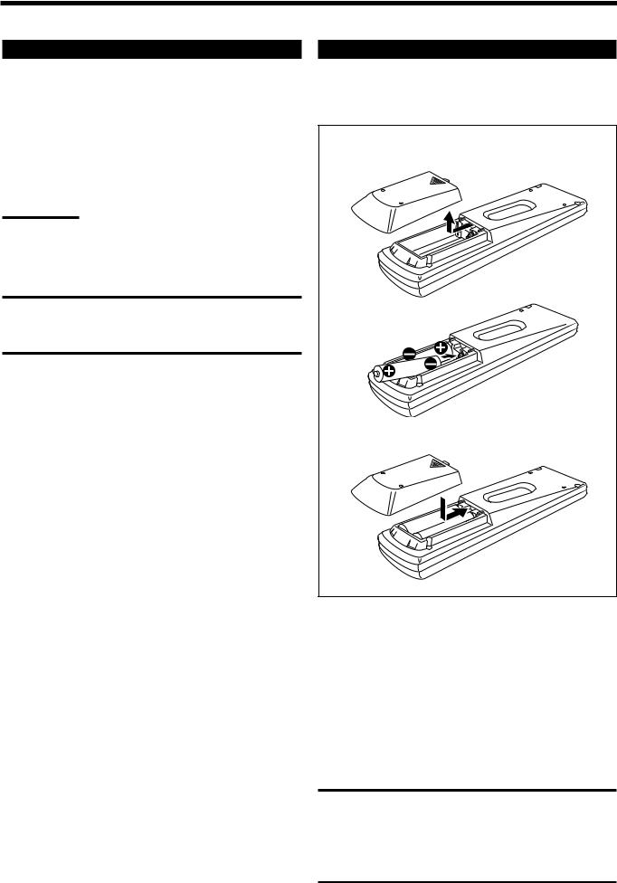
Putting Batteries in the Remote Control
Before using the remote control, put two supplied batteries first. When using the remote control, aim the remote control directly at the remote sensor on the receiver.
1
2
R6P(SUM-3)/AA(15F)
3
1.On the back of the remote control, remove the battery cover.
2.Insert batteries. Make sure to match the polarity:
(+) to (+) and (–) to (–).
3.Replace the cover.
If the range or effectiveness of the remote control decreases, replace the batteries. Use two R6P(SUM-3)/AA(15F) type dry-cell batteries.
CAUTION:
Follow these precautions to avoid leaking or cracking cells:
•Place batteries in the remote control so they match the polarity:
(+) to (+) and (–) to (–).
•Use the correct type of batteries. Batteries that look similar may differ in voltage.
•Always replace both batteries at the same time.
•Do not expose batteries to heat or flame.
9

 Basic Operations
The following operations are commonly used when you play any sound source.
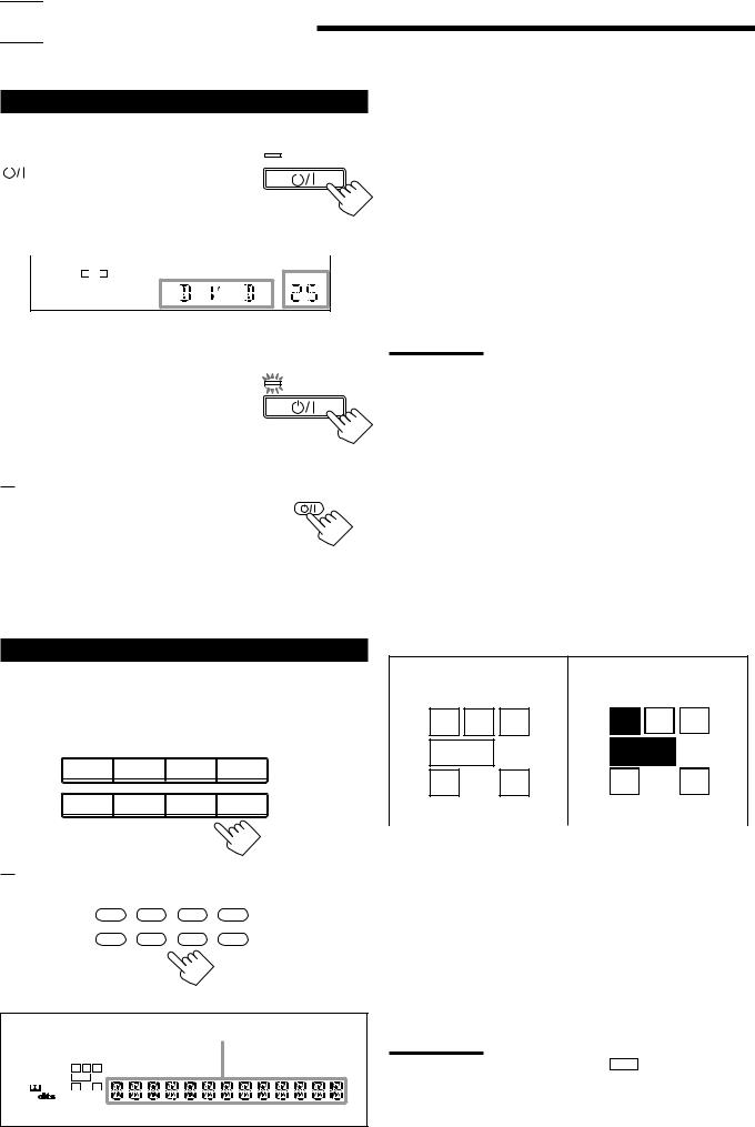
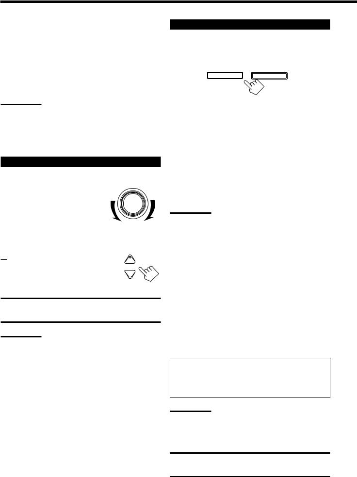
Turning the Power On and Off (Standby)
On the front panel:
To turn on the power, press STANDBY/ON |
STANDBY |
||||
|
|
|
|
||
|
. The STANDBY lamp goes off. The name |
|
|
||
|
|
|
|||
|
|
|
|||
|
|
|
|||
of the current source (or station frequency) |
STANDBY/ON |
||||
appears on the display. |
|
|
|||
|
|
Current source name appears |
|||
|
|
|
|
|
|
|
|
|
|
|
|
|
|
SPK 1 |
|
|
|
|
|
ANALOG L R |
|
VOLUME |
|
Current volume level is shown here 
To turn off the power (into standby mode), press STANDBY/ON  again.
 The STANDBY lamp lights up. A small amount of power is consumed in standby mode. To turn the power off completely, unplug the AC power cord.
From the remote control:
To turn on the power, press AUDIO  . The STANDBY lamp goes off. The name of the current source (or station frequency) appears on the display.
To turn off the power (into standby mode), press AUDIO  again. The STANDBY lamp lights up.
 STANDBY
STANDBY/ON
AUDIO
Selecting the Source to Play
Press one of the source selecting buttons.
On the front panel:
DVD MULTI |
DVD |
VCR |
TV SOUND/DBS |
|
|
|
SOURCE NAME |
PHONO |
CD |
TAPE/CDR |
FM/AM |
|
|
SOURCE NAME |
|
From the remote control:
DVD DVD MUILTI |
CD |
FM/AM |
TV/DBS VCR TAPE/CDR PHONO
Selected source name appears
DIGITAL AUTO |
SPK 1 2 |
BASS BOOST INPUT ATT |
SLEEP |
||
ANALOG |
L |
C |
R |
PROLOGIC DSP H.PHONE AUTOMUTING TUNED STEREO |
VOLUME |
LINEAR PCM |
S.WFR LFE |
|
|
||
DIGITAL |
LS |
S |
RS |
|
|
|
|
|
CH- |
|
|
|
|
|
|
|
|
DVD MULTI |
Select the DVD player for viewing the digital |
|
video disc using the analog discrete output mode |
|
(5.1 CH reproduction). |
|
To enjoy the DVD MULTI playback, see page |
|
27. |
DVD |
Select the DVD player. |
VCR |
Select the video component connected to the |
|
VCR jacks. |
TV SOUND/DBS Select TV sounds (or the DBS tuner). |
|
PHONO* |
Select the turntable. |
CD* |
Select the CD player. |
TAPE/CDR* |
Select the cassette deck (or the CD recorder). |
FM/AM* |
Select an FM or AM broadcast. |
|
• Each time you press the button, the band |
alternates between FM and AM.
Notes:
•When connecting a CD recorder (to the TAPE/CDR jacks), and a DBS tuner (to the TV SOUND/DBS jacks), change the source name shown on the display. For details, see page 13.
•When you press one of the source selecting buttons on the remote control marked above with an asterisk (*), the receiver automatically turns on.
Signal and speaker indicators on the display
The signal indicators light up in the following cases:
•Only the indicators for the incoming signals light up.
•When analog input is selected, “L” and “R” always light up.
•When “DVD MULTI” is selected as the source, “L,” “C,” “R,” “LFE,” “LS” and “RS” light up.
The speaker indicators light up only —:
•When the corresponding speaker is activated.
AND
•When the corresponding speaker is required for the DSP mode selected currently.
Signal indicators light up in |
Speaker indicators light up |
red: |
in white: |
L |
C |
R |
L |
C |
R |
S.WFR LFE |
S.WFR LFE |
||||
LS |
S |
RS |
LS |
S |
RS |
|
|||||
L: • When digital input is selected: Lights up when the left |
|||||
channel signal comes in. |
|
|
|
||
• When analog input is selected: Always lights up. |
|||||
R: • When digital input is selected: Lights up when the right channel signal comes in.
• When analog input is selected: Always lights up.
C: Lights up when the center channel signal comes in. LS: Lights up when the left rear channel signal comes in. RS: Lights up when the right rear channel signal comes in.
S: Lights up when the monaural rear channel signal comes in. LFE: Lights up when the LFE channel signal comes in.
Notes:
• When “SUBWOOFER” is set to “YES,” S.WFR lights up.
•When you select “DVD MULTI,” all the signal indicators except “S” light up.
10
Selecting different sources for picture and sound
You can watch picture from a video component while listening to sound from another component.
Press one of the audio source selecting buttons — PHONO, CD, TAPE/CDR, FM/AM, TV SOUND/DBS* (or TV/DBS on the remote control), while viewing the picture from a video component such as the VCR, DVD player, or DBS tuner, etc.
Notes:
• Once you have selected a video source, pictures of the selected source are sent to the TV until you select another video source.
*The TV SOUND/DBS (or TV/DBS on the remote control) only works for selecting “DBS” as the source but not for selecting “TV SOUND (or TV on the remote control).” When you use the DBS tuner, change the source name correctly (see page 13).
Adjusting the Volume
On the front panel:
To increase the volume, turn MASTER VOLUME clockwise.
To decrease the volume, turn it counterclockwise.
•When you turn MASTER VOLUME rapidly, the volume level also changes rapidly.
•When you turn MASTER VOLUME slowly, the volume level also changes slowly.
From the remote control:
To increase the volume, press VOLUME +. To decrease the volume, press VOLUME –.
CAUTION:
MASTER VOLUME
+
VOLUME
−
Always set the volume to the minimum before starting any source. If the volume is set at its high level, the sudden blast of sound energy can permanently damage your hearing and/or ruin your speakers.
Note:
The volume level can be adjusted within the range of “0” (minimum) to “80” (maximum).
Selecting the Front Speakers
On the front panel ONLY:
When you have connected two pairs of the front speakers, you can select which to use.
SPEAKERS ON/OFF
1 |
2 |
To use the speakers connected to the FRONT SPEAKERS 1 terminals, press SPEAKERS ON/OFF 1 so that the SPK 1 indicator lights up on the display. (Make sure that the SPK 2 is not on the display.)
To use the speakers connected to the FRONT SPEAKERS 2 terminals, press SPEAKERS ON/OFF 2 so that the SPK 2 indicator lights up on the display. (Make sure that the SPK 1 is not on the display.)
To use both sets of the speakers, press SPEAKERS ON/OFF 1 and 2 so that the SPK 1 and SPK 2 indicators light up on the display.
To use neither sets of the speakers, press SPEAKERS ON/OFF 1 and 2 so that the SPK 1 and SPK 2 indicators disappear from the display.
Notes:
•If you select any of the DSP modes while using both the speakers connected to the FRONT SPEAKERS 1 and 2 terminals, the speakers connected to the FRONT SPEAKERS 2 terminals are deactivated.
•While the DSP MODE is in use, you can only select either the speakers connected to the FRONT SPEAKERS 1 or 2 terminals.
Listening only with headphones
You must turn off both pairs of speakers when you listen with headphones.
1.Connect a pair of headphones to the PHONES jack on the front panel.
2.Press SPEAKERS ON/OFF 1 and SPEAKERS ON/OFF 2 so that neither the SPK 1 nor SPK 2 indicator appears on the display.
This cancels the DSP mode currently selected, and activates the HEADPHONE mode (see below).
•“HEADPHONE” appears and H. PHONE indicator lights up on the display.
HEADPHONE mode:
This mode can reproduce the LFE channel signals, mixing them with the front channel signals. So you will not miss the subwoofer sounds even if you listen to a source using the headphones.
Notes:
•While in the HEADPHONE mode, you cannot use any DSP modes (see page 20.)
•Activating the speaker cancels the HEADPHONE mode and turns on the DSP mode previously selected.
CAUTION:
Be sure to turn down the volume before connecting or putting on headphones, as high volume can damage both the headphones and your hearing.
11
Loading...