


AUDIO/VIDEO CONTROL RECEIVER
RX-664VBK
|
|
POWER |
|
CATV/SAT |
TV |
VCR |
AUDIO |
|
CATV |
SOUND |
|
|
CONTROL CD-DISC CONTROL |
||
DAP MODE |
|
3D-PHONIC |
SURROUND |
1 |
|
2 |
3 |
EFFECT |
|
DELAY |
TEST |
4 |
|
5 |
6 |
SEA MODE |
|
SEA PRESET |
MENU |
7/P
100+ |
– REAR•R + |
+10 |
|
CENTER |
REAR |
(L) |
|
SLEEP ONE TOUCH |
|
|
OPERATION |
TUNER/ |
|
BAND |
|
8 |
9 |
|
MASTER VOLUME |
|
|
|
|
|
|
RETURN/ENTER |
RX-664V AUDIO/VIDEO CONTROL RECEIVER |
|
|
|
|
|
|
0 |
10 |
TUNER/BAND |
PRESET SEA |
SOURCE |
SURROUND |
ADJUST |
SETTING |
|
TV |
CH |
– |
+ |
|
|
|
|
|
VOLUME |
|
|
|
|
|
|
|
|
TV/VIDEO |
|
|
MEMORY |
|
|
|
|
|
|
|
|
|
|
|
|
|
|
CD |
TAPE |
|
|
|
|
|
ONE TOUCH OPERATION |
|
|
|
|
|
|
|
|
|
|
TV SOUND
PHONO
VCR
MUTING
DVD MULTI
DVD |
|
DVD |
MULTI |
|
|
VOLUME
STANDBY |
|
PHONES |
SPEAKERS |
1 |
2 |
POWER |
|
|
_ON —OFF |
RM-SR664U
REMOTE CONTROL
INSTRUCTIONS
For Customer Use:
Enter below the Model No. and Serial No. which are located either on the rear, bottom or side of the cabinet. Retain this information for future reference.
Model No.
Serial No.
LET0119-001B
[J]
Warnings, Cautions and Others
|
|
CAUTION |
|
|
|
RISK OF ELECTRIC SHOCK |
|
|
|
DO NOT OPEN |
|
|
|
|
|
|
|
|
|
CAUTION: |
TO REDUCE THE RISK OF ELECTRIC SHOCK. |
||
|
DO NOT REMOVE COVER (OR BACK) |
||
|
NO USER SERVICEABLE PARTS INSIDE. |
||
REFER SERVICING TO QUALIFIED SERVICE PERSONNEL.
CAUTION
To reduce the risk of electrical shocks, fire, etc.:
1.Do not remove screws, covers or cabinet.
2.Do not expose this appliance to rain or moisture.
The lightning flash with arrowhead symbol, within an equilateral triangle is intended to alert the user to the presence of uninsulated "dangerous voltage" within the product's enclosure that may be of sufficient magnitude to constitute a risk of electric shock to persons.
The exclamation point within an equilateral triangle is intended to alert the user to the presence of important operating and maintenance (servicing) instructions in the literature accompanying the appliance.
WARNING: TO REDUCE THE RISK OF FIRE OR ELECTRIC SHOCK, DO NOT EXPOSE THIS APPLIANCE TO RAIN OR MOISTURE.
Caution –– POWER switch!
Disconnect the mains plug to shut the power off completely. The
POWER switch in any position does not disconnect the mains line.
The power can be remote controlled.
G-1
Once you have found the best DVD MULTI playback, DAP, 3D-PHONIC and Surround mode settings for your listening room, note them in the table below for future reference (even though the receiver memorizes the settings until you change them).
For actual setting procedures, see pages 26 to 39.
DVD MULTI Playback Mode
Center Speaker Level
Left Rear Speaker Level
Right Rear Speaker Level
DAP Mode |
|
Dance Club |
|
Live Club |
Hall |
|
|
Pavilion |
Headphones |
||||||||||
|
|
|
|
|
|
|
|
|
|
|
|
|
|
|
|
|
|
|
|
Rear Speaker Level* |
|
|
|
|
|
|
|
|
|
|
|
|
|
|
|
|
|
|
|
|
|
|
|
|
|
|
|
|
|
|
|
|
|
|
|
|
|
||
|
|
|
|
|
|
|
|
|
|
|
|
|
|
|
|
|
|
|
|
Effect Level |
|
|
|
|
|
|
|
|
|
|
|
|
|
|
|
|
|
|
|
|
|
|
|
|
|
|
|
|
|
|
|
|
|
|
|
|
|
|
|
|
|
|
|
|
|
|
|
|
|
|
|
|
|
|
|
|
|
|
|
|
|
|
|
|
|
|
|
|
|
|
|
|
|
|
|||||
3D-PHONIC Mode |
|
3D Action |
|
3D Drama |
3D Theater |
|
|
|
|
|
|
|
|
||||||
|
|
|
|
|
|
|
|
|
|
|
|
|
|
|
|
|
|
|
|
Effect Level |
|
|
|
|
|
|
|
|
|
|
|
|
|
|
|
|
|
|
|
|
|
|
|
|
|
|
|
|
|
|
|
|
|
|
|
|
|
|
|
|
|
|
|
|
|
|
|
|
|
|
|
|
|
|
|
|
|
|
|
Surround Mode |
|
Dolby Pro Logic |
|
Dolby 3ch Logic |
|
Theater Surround |
|
|
|
|
|||||||||
|
|
|
|
|
|
|
|
|
|
|
|
|
|
|
|
|
|
|
|
Center Mode |
|
|
|
|
|
|
|
|
|
|
|
|
|
|
|
|
|
|
|
|
|
|
|
|
|
|
|
|
|
|
|
|
|
|
|
|
|
|
|
Delay Time |
|
|
|
|
|
|
|
|
|
|
|
|
|
|
|
|
|
|
|
|
|
|
|
|
|
|
|
|
|
|
|
|
|
|
|
|
|
||
|
|
|
|
|
|
|
|
|
|
|
|
|
|
|
|
|
|
|
|
Center Speaker Level |
|
|
|
|
|
|
|
|
|
|
|
|
|
|
|
|
|
|
|
|
|
|
|
|
|
|
|
|
|
|
|
|
|
|
|
|
|
|
|
Rear Speaker Level* |
|
|
|
|
|
|
|
|
|
|
|
|
|
|
|
|
|
|
|
|
|
|
|
|
|
|
|
|
|
|
|
|
|
|
|
|
|
||
|
|
|
|
|
|
|
|
|
|
|
|
|
|
|
|
|
|
|
|
Effect Level |
|
|
|
|
|
|
|
|
|
|
|
|
|
|
|
|
|
|
|
|
|
|
|
|
|
|
|
|
|
|
|
|
|
|
|
|
|
||
|
|
|
|
|
|
|
|
|
|
|
|
|
|
|
|
|
|
|
|
* The left rear speaker level and right rear speaker level for DAP and the surround modes cannot be stored separately.
G-2


 Table of Contents
Parts Identification...................................................................................... |
2 |
Easy Set Up & Operations ............................................................................ |
3 |
Getting Started........................................................................................... |
7 |
Before Installation ................................................................................................................................................................... |
7 |
Checking the Supplied Accessories ........................................................................................................................................ |
7 |
Connecting the FM and AM Antennas ................................................................................................................................... |
8 |
Connecting the Speakers ......................................................................................................................................................... |
9 |
Connecting Audio/Video Components ................................................................................................................................. |
11 |
Connecting the Power Cord .................................................................................................................................................. |
13 |
Putting Batteries in the Remote Control ............................................................................................................................... |
13 |
Basic Operations ....................................................................................... |
14 |
Turning the Power On and Off ............................................................................................................................................. |
14 |
Selecting the Source to Play ................................................................................................................................................. |
14 |
Adjusting the Volume ........................................................................................................................................................... |
15 |
Selecting the Front Speakers ................................................................................................................................................. |
15 |
Muting the Sound .................................................................................................................................................................. |
15 |
Recording a Source ............................................................................................................................................................... |
16 |
Listening with Headphones .................................................................................................................................................. |
16 |
Basic Settings........................................................................................... |
17 |
Adjusting the Front Speaker Output Balance ....................................................................................................................... |
17 |
Listening at Low Volume (Loudness) ................................................................................................................................... |
17 |
Using the Sleep Timer ........................................................................................................................................................... |
17 |
Selecting the Center Speaker Size ........................................................................................................................................ |
19 |
One Touch Operation .................................................................................. |
20 |
About the One Touch Operation ........................................................................................................................................... |
20 |
Using the One Touch Operation ........................................................................................................................................... |
20 |
Receiving Radio Broadcasts ........................................................................ |
21 |
Tuning in Stations Manually ................................................................................................................................................. |
21 |
Using Preset Tuning .............................................................................................................................................................. |
21 |
Selecting the FM Reception Mode ....................................................................................................................................... |
23 |
Using the Preset SEA Modes...................................................................... |
24 |
Selecting Your Favorite SEA Mode ...................................................................................................................................... |
24 |
Using the Surround Processor .................................................................... |
26 |
Using JVC 3D-PHONIC Modes ........................................................................................................................................... |
27 |
Using the DAP Modes .......................................................................................................................................................... |
29 |
Speaker Arrangements for Surround Modes ......................................................................................................................... |
32 |
Preparing for Surround Modes ............................................................................................................................................. |
33 |
Using Surround Modes ......................................................................................................................................................... |
37 |
Using the DVD MULTI Playback Mode .......................................................... |
38 |
Speaker arrangements for DVD MULTI playback ............................................................................................................... |
38 |
Activating the DVD MULTI playback ................................................................................................................................. |
38 |
COMPU LINK Remote Control System ......................................................... |
40 |
AV COMPU LINK Remote Control System .................................................... |
41 |
Operating Other Components ..................................................................... |
43 |
Operating Other Manufacturers’ Video Equipment ........................................ |
45 |
Troubleshooting......................................................................................... |
48 |
Specifications............................................................................................ |
49 |
1

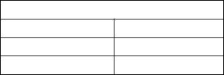
 Parts Identification
Become familiar with the buttons and controls on the receiver before use.
1 |
2 |
3 |
4 |
5 6 |
7 |
8 |
9 |
0 |
- |
|
|
|
MASTER VOLUME |
|
|
|
|
|
|
RX-664V |
AUDIO/VIDEO CONTROL RECEIVER |
|
|
TUNER/BAND |
PRESET SEA |
SOURCE |
SURROUND |
ADJUST |
SETTING |
–+
|
|
|
MEMORY |
|
|
|
|
|
ONE TOUCH OPERATION |
|
|
|
DVD MULTI |
|
STANDBY |
|
|
|
|
|
PHONES |
SPEAKERS |
|
|
|
1 |
|
2 |
|
POWER |
|
|
|
|
|
|
_ON —OFF |
|
|
= |
~ |
! |
@ |
# |
$
%
^
&
*
(
)
_
+
¡
|
|
POWER |
|
|
|
|
CATV/SAT |
TV |
VCR |
|
|
AUDIO |
|
|
|
CATV |
|
|
|
SOUND |
|
CONTROLCD-DISC CONTROL |
|||||
DAP MODE |
3D-PHONIC |
|
SURROUND |
|||
1 |
|
2 |
|
|
|
3 |
EFFECT |
DELAY |
|
|
|
TEST |
|
4 |
|
5 |
|
|
|
6 |
SEA MODE |
SEA PRESET |
|
|
MENU |
||
7/P |
8 |
|
|
|
9 |
|
100+ |
– REAR•R + |
|
|
RETURN/ENTER |
||
+10 |
0 |
|
|
|
10 |
|
CENTER |
|
REAR |
TV |
|
|
CH |
|
|
(L) |
VOLUME |
|
|
|
SLEEP |
ONE TOUCH TV/VIDEO |
|
|
|
||
|
OPERATION |
|
|
|
|
|
|
|
CD |
|
|
TAPE |
|
TUNER/ |
|
|
|
|||
BAND |
|
|
|
|
|
|
TV |
VCR |
|
|
DVD |
||
|
|
|
||||
SOUND |
MUTING |
|
||||
DVD |
|
|||||
|
|
MULTI |
||||
PHONO |
|
|
||||
|
|
|
|
|||
VOLUME
RM-SR664U
REMOTE CONTROL
Refer to the pages in parentheses for details.
™ |
Front Panel |
||
£ |
1 Remote sensor (13) |
||
|
2 |
Display (14) |
|
|
3 |
DVD MULTI button (38) |
|
|
4 |
MASTER VOLUME control (15) |
|
¢ |
5 |
MEMORY button (21) |
|
6 TUNER/BAND button and lamp (21) |
|||
|
7 |
PRESET SEA button and lamp (24) |
|
§ |
|||
8 |
SOURCE button and lamp (14) |
||
|
|||
|
9 |
SURROUND button and lamp (27, 29) |
|
|
0 |
ADJUST button and lamp (27, 29) |
|
¶ |
- SETTING button and lamp (17) |
||
|
= POWER button and STANDBY lamp |
||
(14)
~ PHONES jack (16)
! SPEAKERS 1/2 buttons (15) @ Control %/ fi/ @/ #buttons
# ONE TOUCH OPERATION button and lamp (20)
Remote Control
$ POWER buttons (CATV/SAT, TV, VCR, AUDIO) (14, 45, 46, 47)
% CATV CONTROL button (46) ^ 10 keys/Sound control buttons (22, 25, 28, 30, 35, 36, 37, 39)
& REAR (L) butttons (+/–) (36, 39) * CENTER buttons (+/–) (36, 39)
( ONE TOUCH OPERATION button (20) ) SLEEP button (18)
_ Source buttons (TUNER/BAND, CD, TAPE, TV SOUND, VCR, DVD, PHONO, DVD MULTI) (14, 39, 43, 44, 45, 47)
+ VOLUME buttons (+/–) (15)
¡Operating buttons for JVC audio/video components (43, 44, 47)
™SOUND CONTROL button (25, 28, 30, 35, 37, 39)
£ CD-DISC button (43)
¢CH (Channel) buttons (+/–) (44, 45, 46, 47)
TV VOLUME button (44, 45) § TV/VIDEO button (44, 45) ¶ MUTING button (15)
2

 Easy Set Up & Operations
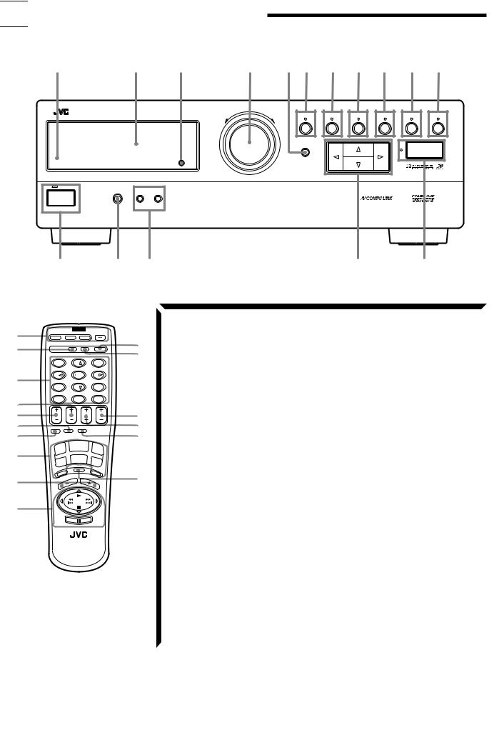
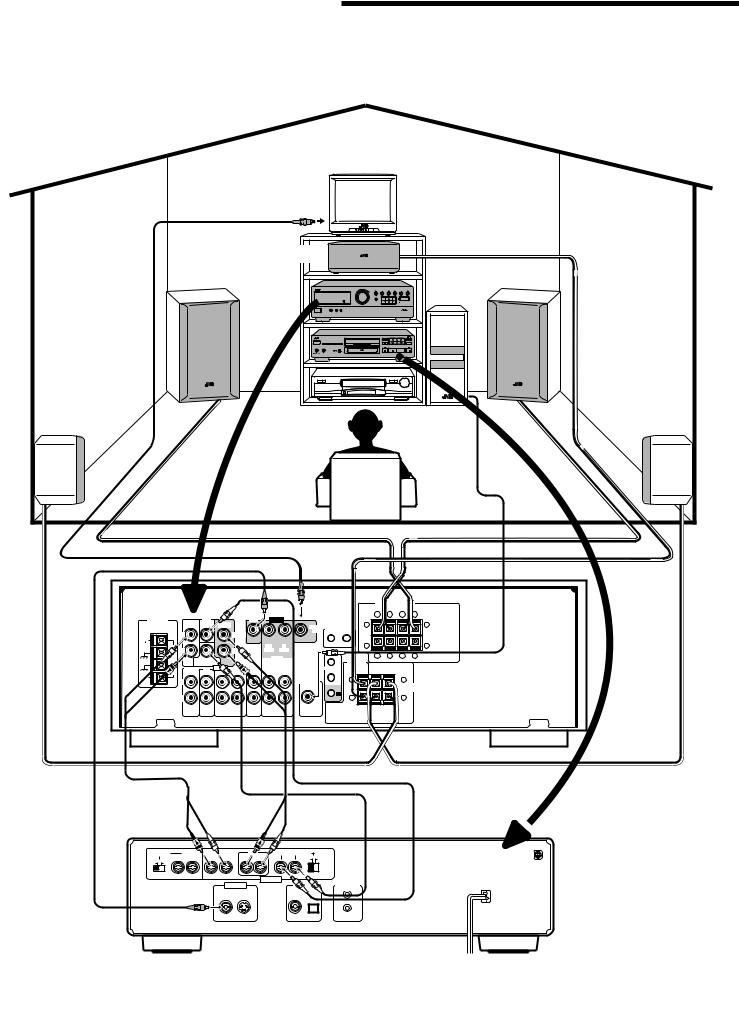
If you are already familiar with audio components, following four pages give you enough information to operate your RX-664VBK for enjoyment of surround sound in your listening room.
For Reproducing Surround Sound with your VCR
TV
To video input
Center Speaker |
|
|
Front Speaker |
|
Front Speaker |
Rear Speaker |
Subwoofer |
Rear Speaker |
|
||
|
|
RX-664VBK |
|
|
|
|
|
|
|
|
|
|
FRONT SPEAKERS |
|
||
|
|
|
|
|
|
|
|
|
|
RIGHT |
LEFT |
|
|
|
|
DVD |
|
|
DVD |
VIDEO |
|
|
+ |
– |
– |
+ |
|
ANTENNA |
|
|
|
|
|
|
|
|
|
||||
|
FRONT CENTER |
REAR |
|
|
|
|
MONITOR |
COMPU LINK-3 |
1 |
|
|
1 |
|
|
|
|
|
|
|
|
|
|
|
|
|
||
|
L |
|
|
LEFT |
|
|
|
OUT |
(SYNCHRO) |
|
|
|
|
FM |
|
|
|
|
|
|
|
|
|
|
|
||
|
|
|
|
|
|
|
|
|
|
|
|
|
|
75 |
|
|
|
|
|
|
|
|
|
2 |
|
|
2 |
FM |
|
|
|
|
|
OUT |
IN |
|
|
|
|
||
GND |
R |
|
|
RIGHT |
|
(REC) |
(PLAY) |
|
|
|
|
|
|
|
|
|
|
|
|
|
|
+ |
– |
– |
+ |
||
|
|
|
|
|
|
VCR |
|
|
|||||
GND |
SUBWOOFER |
|
|
|
CENTER |
|
|
|
|
||||
|
|
|
|
AV |
|
|
|
|
|||||
|
|
|
AUDIO |
|
TV |
|
|
SPEAKER |
|
|
|
|
|
AM |
PHONO |
CD |
TAPE |
OUT |
IN |
COMPU LINK |
RIGHT |
LEFT |
|
|
|||
LOOP |
|
|
|
|
SOUND |
(REC) |
(PLAY) |
LEFT |
|
|
|
|
|
AM |
|
|
|
|
|
|
|
+ |
|
|
+ |
|
|
EXT |
L |
|
|
|
|
|
|
SUBWOOFER |
|
|
|
||
|
|
|
|
|
|
|
|
|
|
||||
|
|
|
|
|
|
|
|
OUT |
|
|
|
REAR |
|
|
|
|
|
|
|
|
|
|
|
|
|
SPEAKERS |
|
|
|
|
|
|
|
|
|
|
TV |
|
|
– |
|
|
R |
|
|
|
|
|
|
|
– |
|
|
|
|
|
|
|
|
|
|
|
|
RIGHT |
|
|
|
|
|
|
|
|
OUT |
IN |
|
|
|
|
|
|
|
|
|
|
|
|
(REC) |
(PLAY) |
|
|
|
|
|
|
|
|
|
To audio/video input
VCR
ANTENNA |
IN OUT |
|
IN OUT |
VIDEO |
|
|
AUDIO |
|
|
L |
|
|
AUDIO |
|
|
R |
To audio/video output |
|
|
|
To RF output |
To TV antenna |
TV |
|
||
|
input |
|
If your TV does not have a video input
3

|
|
MASTER VOLUME |
|
|
|
|
|
RX-664V AUDIO/VIDEO CONTROL RECEIVER |
TUNER/BAND |
PRESET SEA |
SOURCE |
SURROUND |
ADJUST |
SETTING |
|
|
– |
+ |
|
|
|
|
|
|
|
MEMORY |
|
|
|
|
|
|
|
|
|
|
|
ONE TOUCH OPERATION |
|
|
DVD MULTI |
|
|
|
|
|
|
STANDBY |
|
|
|
|
|
|
|
PHONES |
SPEAKERS |
|
|
|
|
|
|
1 |
2 |
|
|
|
|
|
|
POWER
_ON —OFF
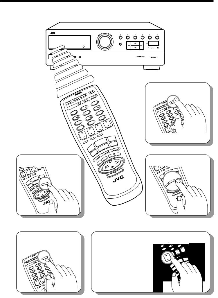
2. Select the source.
CATV/SAT
DAP
POWER |
|
|
AUDIO |
|
||
|
|
|
SOUND |
|||
|
VCR |
|
CONTROL |
|||
TV |
|
|
|
|||
|
-DISC |
|
|
|
||
|
|
|
SURROUND |
|||
CATV |
CD |
|
|
|||
|
|
|
|
3 |
||
CONTROL |
|
|
|
|||
|
|
-PHONIC |
|
|
TEST |
|
|
3D |
|
|
|
6 |
|
MODE |
|
2 |
|
|
|
|
|
DELAY |
|
|
MENU |
||
1 |
|
|
|
|||
|
5 |
|
|
9 |
||
EFFECT |
SEA |
PRESET |
RETURN/ENTER |
|||
4 |
MODE |
|
8 |
|
10 |
|
SEA |
|
|
|
|
|
|
|
.R |
|
0 |
|
||
7/P |
REAR |
|
|
CH |
||
|
|
|
|
|
||
100+ |
|
|
|
|
TV |
|
|
+10 |
|
|
|
VOLUME |
|
|
REAR) |
|
|
|
|
|
(L |
|
|
|
|
CENTER |
|
|
TV/VIDEO |
|
|
|
|
|
TAPE |
|
|
|
|
TOUCH |
|
|
|
|
|
CD |
|
|
|
|
OPERATION |
|
|
||
|
ONE |
|
|
|
|
SLEEP |
TUNER/ |
|
DVD |
||
|
VCR |
DVD |
MULTI |
||
|
BAND |
|
|||
|
MUTING |
|
|
||
|
|
TV |
|
|
|
|
|
|
|
|
|
|
SOUND |
VOLUME |
|
||
|
|
PHONO |
|
||
|
|
|
|
|
|
100+ |
|
|
TV |
|
|
|
|
+10 |
|
VOLUME |
|
|
|
|
|
|
REAR) |
|
|
|
|
|
|
|
(L |
|
|
|
|
|
|
CENTER |
|
|
TV/VIDEO |
|
|
|
|
|
|
|
TAPE |
|
|
|
|
|
TOUCH |
|
|
|
|
|
|
|
|
CD |
|
|
|
|
|
|
OPERATION |
|
|
|
|
|
|
|
ONE |
|
|
|
|
|
|
SLEEP |
|
|
|
DVD |
|
|
|
|
TUNER/ |
|
VCR |
DVD |
MULTI |
|
|
|
BAND |
|
MUTING |
|
|
|
|
|
TV |
|
|
|
|
|
|
|
|
|
|
|
|
|
|
|
SOUND |
|
VOLUME |
|
|
-SR664U |
|
|
PHONO |
|
|
|
RM |
CONTROL |
|
|
|
|
|
REMOTE |
|
||
|
|
|
|
|
|
|
|
|
|
|
|
|
-SR664U |
|
|
|
|
|
|
|
RM |
CONTROL |
|
|
|
|
|
|
REMOTE |
|
|
1. Turn on the power.
|
|
AUDIO |
|
|
|
|
POWERVCR |
SOUND |
|
||
|
TV |
|
CONTROL |
|
|
|
-DISC |
|
|
|
|
CATV/SAT |
|
SURROUND |
|
||
CATV |
CD |
|
|||
|
|
|
|
|
|
|
CONTROL |
|
3 |
|
|
|
|
-PHONIC |
|
TEST |
|
|
3D |
|
|
||
|
MODE |
2 |
|
6 |
|
DAP |
DELAY |
|
MENU |
||
1 |
|
||||
|
5 |
|
|
9 |
|
|
EFFECT |
SEAPRESET |
RETURN/ENTER |
||
|
4 |
8 |
|
|
10 |
|
MODE |
|
|
|
|
|
SEA |
.R |
0 |
|
|
|
7/P |
REAR |
|
CH |
|
|
|
|
|||
|
100+ |
|
|
|
TV |
|
+10 |
|
VOLUME |
||
|
|
|
REAR) |
|
|
|
|
|
(L |
|
|
|
|
CENTER |
|
|
TV/VIDEO |
|
|
|
|
|
|
|
|
|
TOUCH |
TAPE |
|
|
|
|
CD |
||
|
|
|
PERATION |
||
|
|
|
ONE |
|
|
3. Adjust the volume.
|
(L |
|
|
|
CENTER |
|
TV/VIDEO |
|
|
|
|
TAPE |
|
|
|
TOUCH |
|
|
|
|
CD |
|
|
|
|
OPERATION |
|
|
|
|
ONE |
|
|
|
SLEEP |
TUNER/ |
|
DVD |
|
|
VCR |
DVD |
MULTI |
|
|
BAND |
MUTING |
|
|
|
|
|
|
|
|
TV |
VOLUME |
|
|
|
SOUND |
VOLUME |
|
|
|
PHONO |
|
|
|
|
|
|
|
|
-SR664U |
|
RM |
CONTROL |
REMOTE |
|
4. Set the remote control to sound operation mode.
|
|
|
|
AUDIO |
|
POWERVCR |
|
SOUNDUND |
|
|
TV |
|
CONTROL |
|
|
|
|
|
ROL |
CATV/SAT |
|
-DISC |
SURROUND |
|
CATV |
CD |
|
||
|
|
|
|
|
|
CONTROL |
|
|
3 |
|
-PHONIC |
|
TEST |
|
|
3D |
2 |
|
|
|
MODE |
|
6 |
|
DAP |
DELAY |
|
||
1 |
|
|||
|
5 |
|
||
|
EFFECT |
SEA |
PRESET |
|
|
4 |
8 |
||
|
|
|||
|
MODE |
|
|
|
|
SEA |
.R |
0 |
|
|
7/P |
|||
|
REAR |
|
||
|
|
|
||
|
100+ |
|
|
|
|
+10 |
|
|
|
|
|
|
|
REAR) |
|
|
|
|
(L |
|
CENTER |
|
|
|
|
|
|
|
TOUCH |
|
|
|
|
OPERATION |
|
|
|
|
ONE |
|
|
SLEEP |
|
|
5. Surround settings are preset at the factory. However, if you need to make further adjustments, see pages 26 to 37.
|
|
|
AUDIO |
|
|
|
||
|
POWERVCR |
|
SOUND |
|
|
|
||
|
TV |
|
CONTROL |
|
|
|
||
CATV/SAT |
-DISC |
SURROUND |
|
|
||||
|
|
|
||||||
|
CATV |
CD |
|
|
|
|
|
|
|
|
|
|
|
|
|
|
|
|
CONTROL |
|
|
3 |
|
|
|
|
|
|
-PHONIC |
|
|
|
|
|
|
|
|
|
|
TEST |
|
|
|
|
|
3D |
|
|
|
|
|
||
|
MODE |
2 |
|
|
6 |
|
|
|
DAP |
DELAY |
|
|
MENU |
|
|
||
1 |
|
|
|
|
||||
|
5 |
|
|
|
9 |
|
|
|
|
EFFECT |
SEAPRESET |
RETURN/ENTER |
|
|
|||
|
4 |
8 |
|
|
10 |
|
|
|
|
MODE |
|
|
|
|
|
|
|
|
SEA |
.R |
|
0 |
|
|
|
|
|
7/P |
REAR |
|
|
|
CH |
|
|
|
|
|
|
|
|
|||
|
100+ |
|
|
|
|
TV |
|
|
|
+10 |
|
|
VOLUME |
|
|
||
|
|
|
REAR) |
|
|
|
|
|
|
|
|
|
(L |
|
|
|
|
|
|
CENTER |
|
|
|
TV/VIDEO |
|
|
|
|
|
|
|
|
TAPE |
|
|
|
|
|
|
|
TOUCH |
|
|
|
|
|
|
|
|
CD |
|
|
|
|
|
|
|
OPERATION |
|
|
||
|
|
|
|
ONE |
|
|
|
|
|
|
SLEEP |
|
|
|
DVD |
||
|
|
|
TUNER/ |
VCR |
DVD |
MULTI |
||
|
|
|
|
BAND |
MUTING |
|
||
|
|
|
|
|
TV |
|
||
|
|
|
|
|
|
|
|
|
|
|
|
|
|
OUND |
|
UME |
|
4
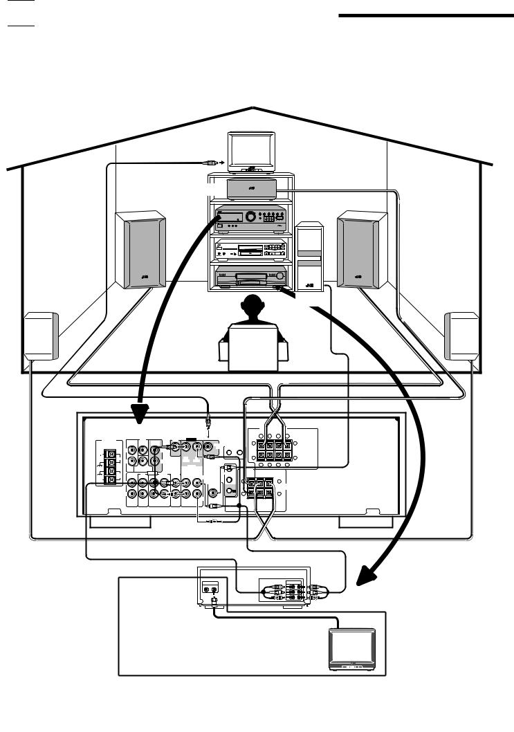
Easy Set Up & Operations
For Reproducing DVD MULTI Playback with your DVD player
|
TV |
To video input |
|
Center Speaker |
|
Front Speaker |
Front Speaker |
|
Subwoofer |
Rear Speaker |
Rear Speaker |
|
RX-664VBK |
FRONT SPEAKERS
|
|
|
|
|
|
RIGHT |
|
|
LEFT |
|
|
DVD |
DVD |
VIDEO |
+ |
– |
– |
+ |
|
|
ANTENNA |
|
|
|
|
||||
|
|
FRONT CENTER REAR |
|
|
MONITOR |
1 |
|
|
1 |
|
|
|
|
|
COMPU LINK-3 |
|
|
|
|
|
|
L |
LEFT |
|
OUT |
(SYNCHRO) |
|
|
|
FM |
|
|
|
|
|
|
|
||
|
|
|
|
|
|
|
|
|
|
75 |
|
|
|
|
|
2 |
|
|
2 |
GND |
|
FM |
|
OUT |
IN |
|
|
||
|
R |
RIGHT |
(REC) |
(PLAY) |
|
|
|
|
|
|
|
|
|
+ |
– |
– |
+ |
||
|
|
|
|
VCR |
|||||
GND |
SUBWOOFER |
|
|
|
|
AV |
CENTER |
|
||
|
|
|
AUDIO |
|
TV |
|
|
SPEAKER |
|
|
AM |
PHONO |
CD |
TAPE |
OUT |
IN |
COMPU LINK |
RIGHT |
LEFT |
||
LOOP |
|
|
|
|
SOUND |
(REC) |
(PLAY) |
LEFT |
|
|
AM |
|
|
|
|
|
|
|
+ |
+ |
|
EXT |
L |
|
|
|
|
|
|
SUBWOOFER |
||
|
|
|
|
|
|
|
||||
|
|
|
|
|
|
|
|
OUT |
|
REAR |
|
|
|
|
|
|
|
|
|
|
SPEAKERS |
|
|
|
|
|
|
|
|
|
TV |
– |
|
R |
|
|
|
|
|
|
|
– |
|
|
|
|
|
|
|
|
|
RIGHT |
|
|
|
|
|
OUT |
IN |
|
|
|
|
|
|
|
|
|
(REC) |
(PLAY) |
|
|
|
|
|
|
To front |
left/ |
|
|
|
|
|
|
|
right channel |
|
To rear left/ |
|
|
|
|
||
audio output |
|
|
|
|
To center |
|||
|
right channel |
|
|
To |
||||
|
|
|
audio output |
|
|
subwoofer |
channel |
|
|
|
|
|
|
|
|
audio output |
audio output |
ATTENUATOR |
2CH |
FRONT |
REAR |
CENTER |
SUBWOOFER |
|
|
|
|
RIGHT |
LEFT |
RIGHT LEFT |
RIGHT LEFT |
|
NORMAL |
GAIN PLUS |
|
OFF |
ON |
|
|
|
|
|
|
|
To video |
|
|
|
AUDIO OUT |
|
|
|
|
output |
|
|
VIDEO OUT |
|
DIGITAL OUT |
AV COMPU LINK |
|
|
|
|
VIDEO |
S-VIDEO |
|
PCM/DOLBY DIGITAL |
|
||
|
|
|
|
COAXIAL OPTICAL |
|
|||
DVD Player
1
5
|
|
MASTER VOLUME |
|
|
|
|
|
RX-664V AUDIO/VIDEO CONTROL RECEIVER |
TUNER/BAND |
PRESET SEA |
SOURCE |
SURROUND |
ADJUST |
SETTING |
|
|
– |
+ |
|
|
|
|
|
|
|
MEMORY |
|
|
|
|
|
|
|
|
|
|
|
ONE TOUCH OPERATION |
|
|
DVD MULTI |
|
|
|
|
|
|
STANDBY |
|
|
|
|
|
|
|
PHONES |
SPEAKERS |
|
|
|
|
|
|
1 |
2 |
|
|
|
|
|
|
POWER
_ON —OFF
CATV/SAT
DAP
POWER |
|
|
AUDIO |
|
||
|
|
|
SOUND |
|||
|
VCR |
|
CONTROL |
|||
TV |
|
|
|
|||
|
-DISC |
|
|
|
||
|
|
|
SURROUND |
|||
CATV |
CD |
|
|
|||
|
|
|
|
3 |
||
CONTROL |
|
|
|
|||
|
|
-PHONIC |
|
|
TEST |
|
|
3D |
|
|
|
6 |
|
MODE |
|
2 |
|
|
|
|
|
DELAY |
|
|
MENU |
||
1 |
|
|
|
|||
|
5 |
|
|
9 |
||
EFFECT |
SEA |
PRESET |
RETURN/ENTER |
|||
4 |
MODE |
|
8 |
|
10 |
|
SEA |
|
|
|
|
|
|
|
.R |
|
0 |
|
||
7/P |
|
|
||||
REAR |
|
|
CH |
|||
|
|
|
|
|
||
100+ |
|
|
|
|
TV |
|
|
+10 |
|
|
|
VOLUME |
|
|
REAR) |
|
|
|
(L |
|
|
CENTER |
|
|
TV/VIDEO |
|
|
|
|
|
|
TOUCH |
TAPE |
|
|
CD |
|
|
OPERATION |
||
|
ONE |
|
|
SLEEP |
|
|
DVD |
2. Select the source.
7 |
REA |
|
|
CH |
|
00+ |
|
|
|
TV |
|
+10 |
|
VOLUME |
|
||
|
|
REAR) |
|
|
|
|
|
(L |
|
|
|
|
CENTER |
|
|
TV/VIDEO |
|
|
|
|
|
TAPE |
|
|
|
TOUCH |
|
|
|
|
|
|
CD |
|
|
|
|
OPERATION |
|
|
|
|
|
ONE |
|
|
|
|
SLEEP |
|
|
|
DVD |
|
|
TUNER/ |
|
|
MULTI |
|
|
|
VCR |
DVD |
|
|
|
BAND |
|
||
|
|
|
MUTING |
|
|
|
|
TV |
|
|
|
|
|
|
|
|
|
|
|
SOUND |
|
VOLUME |
|
|
|
PHONO |
|||
|
|
|
|
||
TUNER/ |
VCR |
DVD |
MULTI |
BAND |
MUTING |
|
|
TV |
|
|
|
|
|
|
|
SOUND |
VOLUME |
|
|
PHONO |
|
|
|
|
|
|
-SR664U |
|
RM |
CONTROL |
REMOTE |
|
- RM REMOTE
1. Turn on the power.
|
|
AUDIO |
|
|
|
|
POWERVCR |
SOUND |
|
||
|
TV |
|
CONTROL |
|
|
|
-DISC |
|
|
|
|
CATV/SAT |
|
SURROUND |
|
||
CATV |
CD |
|
|||
|
|
|
|
|
|
|
CONTROL |
|
3 |
|
|
|
|
-PHONIC |
|
TEST |
|
|
3D |
|
|
||
|
MODE |
2 |
|
6 |
|
DAP |
DELAY |
|
MENU |
||
1 |
|
||||
|
5 |
|
|
9 |
|
|
EFFECT |
SEAPRESET |
RETURN/ENTER |
||
|
4 |
8 |
|
|
10 |
|
MODE |
|
|
|
|
|
SEA |
.R |
0 |
|
|
|
7/P |
REAR |
|
CH |
|
|
|
|
|||
|
100+ |
|
|
|
TV |
|
+10 |
|
VOLUME |
||
|
|
|
REAR) |
|
|
|
|
|
(L |
|
|
|
|
CENTER |
|
|
TV/VIDEO |
|
|
|
|
|
|
|
|
|
TOUCH |
TAPE |
|
|
|
|
CD |
||
|
|
|
OPERATION |
||
|
|
|
ONE |
|
|
|
|
SLEEP |
|
|
DVD |
3. Adjust the volume.
|
(L |
|
|
|
CENTER |
|
TV/VIDEO |
|
|
|
|
TAPE |
|
|
|
TOUCH |
|
|
|
|
CD |
|
|
|
|
OPERATION |
|
|
|
|
ONE |
|
|
|
SLEEP |
TUNER/ |
|
DVD |
|
|
VCR |
DVD |
MULTI |
|
|
BAND |
|
||
|
MUTING |
|
|
|
|
|
|
|
|
|
TV |
VOLUME |
|
|
|
SOUND |
VOLUME |
|
|
|
PHONO |
|
|
|
|
|
|
|
|
4. Set the remote control to sound operation mode.
|
|
|
|
AUDIO |
|
POWERVCR |
|
SOUNDUND |
|
|
TV |
|
CONTROL |
|
|
|
|
|
ROL |
CATV/SAT |
|
-DISC |
SURROUND |
|
CATV |
CD |
|
||
|
|
|
|
|
|
CONTROL |
|
|
|
|
|
-PHONIC |
|
|
|
3D |
|
|
|
|
MODE |
2 |
|
|
DAP |
DELAY |
|
||
1 |
|
|||
|
5 |
|
||
|
EFFECT |
SEA |
PRESET |
|
|
4 |
8 |
||
|
|
|||
|
MODE |
|
|
|
|
SEA |
.R |
0 |
|
|
7/P |
|||
|
REAR |
|
||
|
|
|
||
|
100+ |
|
|
|
|
+10 |
|
|
|
|
|
|
|
REAR) |
|
|
|
|
(L |
|
|
CENTER |
|
|
|
|
|
|
ONE |
|
|
SLEEP |
||
|
|
|
|
UNER/ND |
5. Surround settings are preset at the factory. However, if you need to make further adjustment, see pages 38 and 39.
|
|
|
|
|
|
R |
|
|
EFFECT |
SEAPRESET |
RETURN/ENTE |
|
|
||||
4 |
|
8 |
|
|
10 |
|
|
|
MODE |
|
|
|
|
|
|
|
|
SEA |
.R |
|
0 |
|
|
|
|
|
7/P |
REAR |
|
|
|
CH |
|
|
|
|
|
|
|
|
|
|||
100+ |
|
|
|
|
|
TV |
|
|
+10 |
|
|
|
VOLUME |
|
|
||
|
|
|
REAR) |
|
|
|
|
|
|
|
|
(L |
|
|
|
|
|
CENTER |
|
|
|
|
TV/VIDEO |
|
|
|
|
|
|
|
TOUCH |
|
|
TAPE |
|
|
|
|
|
|
CD |
|
|
|
|
|
|
OPERATION |
|
|
|
||
|
|
|
ONE |
|
|
|
|
|
|
SLEEP |
TUNER/ |
|
|
DVD |
|||
|
|
|
|
VCR |
DVD |
MULTI |
||
|
|
|
BAND |
|
MUTING |
|
|
|
|
|
|
|
TV |
|
|
|
|
|
|
|
|
|
|
|
|
|
|
|
|
SOUND |
|
VOLUME |
|
|
|
|
|
|
|
PHONO |
|
|
||
|
|
|
|
|
|
|
||
-SR664U |
|
RM |
CONTROL |
REMOTE |
|
6


 Getting Started
This section explains how to connect stereo components and speakers to the receiver, and how to connect the power supply.
Before Installation
General
•Be sure your hands are dry.
•Turn the power off to all components.
•Read the manuals supplied with the components you are going to connect.
Locations
•Install the receiver in a location that is level and protected from moisture.
•The temperature around the receiver must be between 23˚ and 95˚ F (–5˚ and 35˚ C).
•Make sure there is good ventilation around the receiver. Poor ventilation could cause overheating and damage the receiver.
Handling the receiver
•Do not insert any metal object into the receiver.
•Do not disassemble the receiver or remove screws, covers, or cabinet.
•Do not expose the receiver to rain or moisture.
Checking the Supplied Accessories
Check to be sure you have all of the following items, which are supplied with the receiver.
The number in the parentheses indicates quantity of the pieces supplied.
•Remote Control (1)
•Batteries (2)
•AM Loop Antenna (1)
•FM Antenna (1)
If anything is missing, contact your dealer immediately.
7
Connecting the FM and AM Antennas
FM Antenna Connections
1 |
2 |
3 |
FM Antenna
|
ANTENNA |
Extend the FM antenna horizontally. |
|
|
|
|
|
||
FM |
|
|
|
|
75 |
|
|
|
|
GND |
FM |
|
Outside FM Antenna Cable |
|
|
|
|||
|
|
|
|
|
GND |
|
1 |
2 |
3 7/16 in. |
|
AM |
|
|
|
AM |
LOOP |
|
|
|
|
|
13/16 in. |
|
|
EXT |
|
|
|
(10 mm) |
|
|
|
|
|
|
|
|
(20 mm) |
|
Note:
If reception is poor, connect the outside antenna.
Before attaching a 75 Ω coaxial cable (the kind with a round wire going to an outside antenna), disconnect the supplied FM wire antenna.
How to strip the 75 Ω coaxial cable and connect it to the FM terminals
1.Strip back the outside covering of the 75 Ω coaxial cable to expose the braided metallic mesh about 13/16 inches (20 mm).
2.Pull the mesh back and twist it into a single connector as shown in the illustration above.
3.Strip the insulation about 7/16 inches (10 mm) back from the central wire.
4.Insert the twisted mesh and the central wire to the FM terminals, as shown in the illustration above.
AM Antenna Connections
ANTENNA |
Turn the loop until you have |
|
|
|
the best reception. |
FM
75
FM
GND
AM Loop Antenna
GND
AM
LOOP
AM
EXT
Snap the tabs on the loop into the slots of the base to assemble the AM loop.
1 |
2 |
3 |
Outdoor Single Vinylcovered Wire
Notes :
•Make sure the antenna conductors do not touch any other terminals, connecting cords and power cord. This could cause poor reception.
•If reception is poor, connect an outdoor single vinyl-covered wire to the AM EXT terminal. (Keep the AM loop antenna connected.)
8
Getting Started
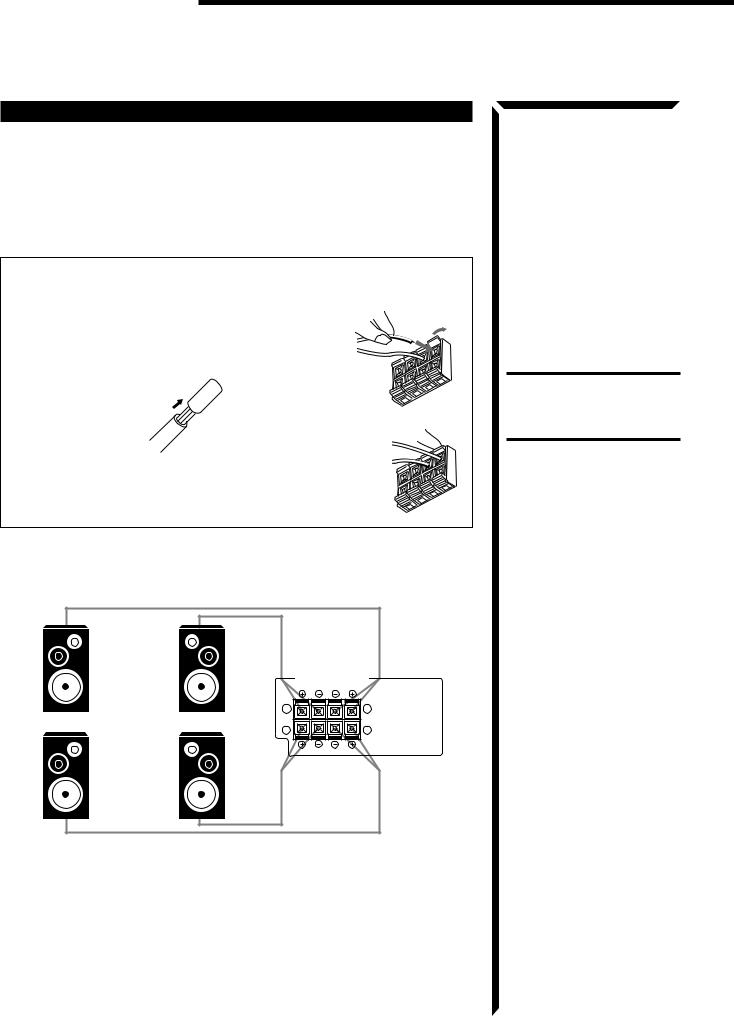
Connecting the Speakers
You can connect the following speakers:
•Two sets of front speakers to produce normal stereo sound
•One set of rear speakers to enjoy the surround effect
•One center speaker to produce more effective surround effect (to make human voices outstanding)
•One subwoofer to enhance the bass
For each speaker (except for subwoofer), connect one end of the speaker signal cable (not supplied) to the speaker terminal on the rear panel and the other end to the speaker. (For connecting a subwoofer, see page 10.)
1. Open each terminal.
2. Insert the end of the speaker signal cable as shown (be sure to remove the insulation at the end of each wire first). 
3. Close the terminals to clamp the speaker signal cables firmly in place.
4. Connect the (–) and (+) terminals on the rear panel to the (–) and (+) terminals marked on the speakers.
Connecting the front speakers
Connect the front speakers to the FRONT SPEAKERS terminals.
SPEAKERS 1 |
FRONT SPEAKERS |
|
|
RIGHT |
LEFT |
|
1 |
1 |
Left speaker |
Right speaker |
2 |
|
2 |
|
SPEAKERS 2 |
|
|
CAUTION:
When connecting speakers, use speakers with the SAME IMPEDANCE indicated by the speaker terminals.
9
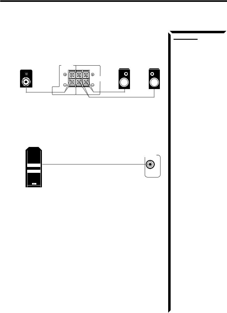
Connecting the rear and center speakers
Connect the rear speakers to the REAR SPEAKERS terminals and the center speaker to the CENTER SPEAKER terminals.
Center |
|
Left rear |
Right rear |
|
CENTER |
speaker |
speaker |
||
speaker |
||||
SPEAKER |
LEFT |
|
||
|
RIGHT |
|
||
|
|
REAR |
|
|
|
|
SPEAKERS |
|
Connecting the subwoofer
Connect the input jack of a powered subwoofer to the SUBWOOFER OUT jack on the rear panel, using a cable with RCA pin plugs.
SUBWOOFER
OUT
Powered subwoofer
Notes:
•When you connect rear speakers, make sure that both left and right speakers are connected; otherwise, no sound will come out of the rear speakers.
•You can register the center speaker size after you finish its connection. If you register it, you do not have to set the center speaker mode while setting the surround mode. (If you do not use a center speaker, register that information.) See page 19.
10
Getting Started
Connecting Audio/Video Components
You can connect the following components to the receiver using cables with RCA pin plugs.
Audio Components |
Video Components |
||
• |
Turntable |
• |
TV |
• |
CD player |
• |
VCR |
|
|
|
|
• |
Cassette deck |
• |
DVD player |
|
|
|
|
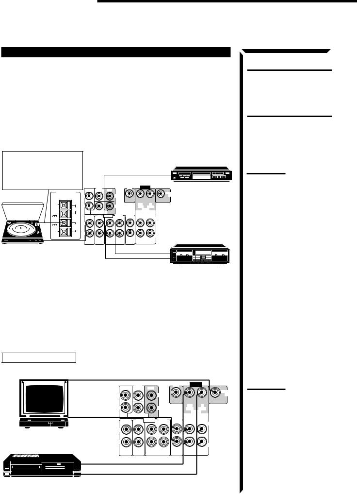
Audio component connections
If a ground cable is provided for your turntable, connect the cable to the GND terminal of the AM LOOP terminals on the rear panel.
ANTENNA
FM 75
FM
GND
GND
AM
LOOP
AM
EXT
|
Turntable |
|
To audio |
|
|
output |
|
|
|
|
|
|
|
|
To audio output |
|||
|
DVD |
|
|
DVD |
|
CD player |
|
FRONT |
CENTER |
REAR |
|
|
|
|
|
|
|
|
|
|
|
MONITOR |
|
L |
|
|
LEFT |
|
|
OUT |
|
|
|
|
RIGHT |
|
OUT |
IN |
|
R |
|
|
|
(REC) |
(PLAY) |
||
|
|
|
|
||||
|
|
|
|
|
VCR |
||
SUBWOOFER |
|
TV |
OUT |
IN |
|||
PHONO |
CD |
AUDIO |
TAPE |
||||
SOUND |
(REC) |
(PLAY) |
|||||
|
|
|
|
|
LEFT |
||
|
|
|
|
|
|
||
L |
|
|
|
|
|
|
|
R
RIGHT
OUT IN (REC) (PLAY)
To audio output
To audio input
Cassette deck
If your audio components have a COMPU LINK-3 terminal
The COMPU LINK remote control system allows you to control other JVC audio components from the receiver or vice versa.
For detailed information about the COMPU LINK-3 remote control system, see page 40.
Video component connections
TV and VCR connection
 To video input (see note to the right)
|
|
|
DVD |
|
|
DVD |
VIDEO |
|
|
|
FRONT |
CENTER |
REAR |
|
|
|
|
|
|
|
|
|
|
|
|
MONITOR |
|
|
L |
|
|
LEFT |
|
|
OUT |
|
|
|
|
|
RIGHT |
|
OUT |
IN |
|
|
R |
|
|
|
(REC) |
(PLAY) |
|
|
|
|
|
|
|
|||
|
|
|
|
|
|
|
VCR |
|
|
|
SUBWOOFER |
|
TV |
OUT |
IN |
||
|
To audio output |
PHONO |
CD |
AUDIO |
TAPE |
|||
|
SOUND |
(REC) |
(PLAY) |
|||||
|
|
|
|
|
|
LEFT |
||
TV |
|
L |
|
|
|
|
|
|
|
|
|
|
|
|
|
|
|
|
|
R |
|
|
|
|
|
RIGHT |
|
|
|
|
|
|
|
|
|
|
|
|
|
OUT |
IN |
|
|
|
|
|
|
|
(REC) |
(PLAY) |
|
|
|
|
To audio/video input |
VHS |
|
VCR |
To audio/video output |
|
CAUTION:
If you connect a sound-enhancing device such as a graphic equalizer between the source components and this receiver, the sound output through this receiver may be distorted.
Note:
Any turntables incorporating a small-output cartridge such as an MC (moving-coil type) must be connected to the receiver through a commercial head amplifier or step-up transformer. Direct connection may result in unsufficient volume.
Note:
When connecting a JVC TV:
•If you use the AV COMPU LINK remote control system to operate the TV, connect the receiver to the Video Input 2 jack on the TV.
•If you do not use the AV COMPU LINK remote control system to operate the TV, connect the receiver to the
Video Input 1 jack on the TV.
11
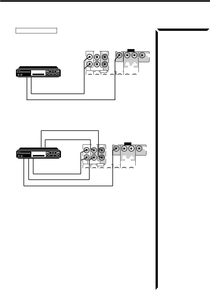
DVD player connection
• When you play back a disc on the DVD player in stereo (or the audio output setting of the DVD player is mixed to two front channels):
|
DVD |
DVD |
VIDEO |
|
FRONT CENTER REAR |
|
|
|
|
|
MONITOR |
L |
LEFT |
|
OUT |
|
|
|
DVD player |
R |
|
RIGHT |
|
(REC) |
(PLAY) |
|
|
|
|
|
OUT |
IN |
|
|
|
|
|
VCR |
|
|
SUBWOOFER |
|
TV |
OUT |
IN |
|
|
PHONO |
CD AUDIO |
TAPE |
|||
|
(REC) |
(PLAY) |
||||
|
SOUND |
|||||
|
|
|
|
|
LEFT |
|
DVD |
|
|
|
|
|
|
|
|
|
|
|
|
|
|
L |
|
|
|
|
|
To front left/right channel |
R |
|
|
audio output (or to audio |
RIGHT |
||
|
|||
mixed output if necessary) |
OUT |
IN |
|
(REC) |
(PLAY) |
||
To video output |
|
|
• When you play back a disc on the DVD player with its analog discrete output mode (5.1 CH reproduction) selected:
To rear left/right channel audio output
To center channel audio output
DVD player
DVD |
DVD |
VIDEO |
FRONT CENTER |
REAR |
|
DVD |
|
|
|
MONITOR |
L |
LEFT |
|
OUT |
|
RIGHT |
OUT |
IN |
R |
(REC) |
(PLAY) |
To front left/right channel audio output
To subwoofer audio output
To video output
|
|
|
|
VCR |
|
SUBWOOFER |
|
TV |
OUT |
IN |
|
PHONO CD AUDIO |
TAPE |
||||
(REC) |
(PLAY) |
||||
SOUND |
|||||
|
|
|
LEFT |
||
|
|
|
|
||
L |
|
|
|
|
|
R |
|
|
|
RIGHT |
|
|
|
|
|
||
OUT |
IN |
|
|
|
|
(REC) |
(PLAY) |
|
|
|
If your audio components have an AV COMPU LINK terminal
The AV COMPU LINK remote control system allows you to control other JVC video components from the receiver or vice versa.
For detailed information about the connection and the AV COMPU LINK remote control system, see page 41.
12
Getting started
Connecting the Power Cord
Before plugging the receiver into an AC outlet, make sure that all connections have been made.
When the power cord is connected, the STANDBY lamp above the POWER button lights up.
Keep the power cord away from the connecting cables for the TV, VCR, and antenna. The power cord may cause noise or screen interference. We recommend that you use a coaxial cable to connect the antenna, since it is well-shielded against interference.
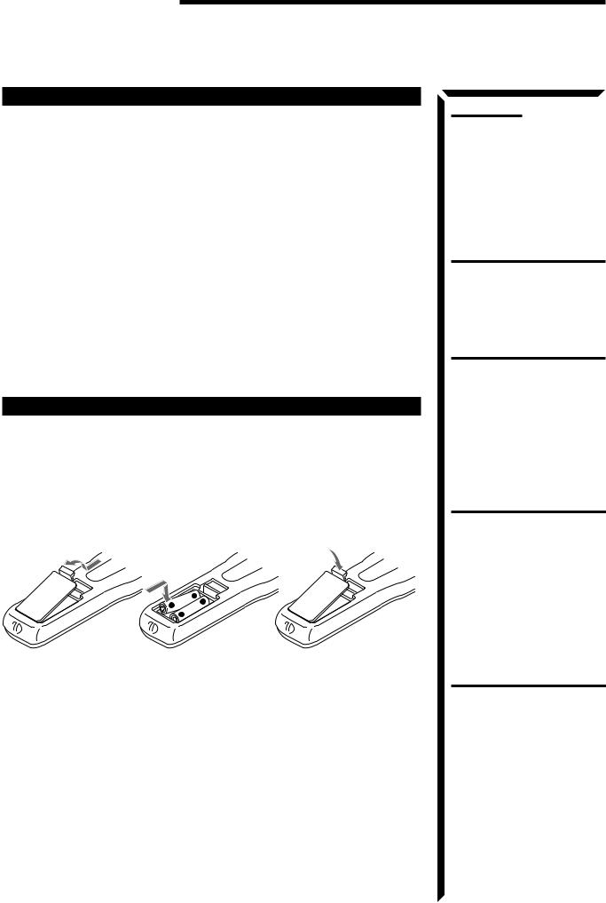
Putting Batteries in the Remote Control
Before using the remote control, put the two supplied batteries in first. When using the remote control, aim the remote control directly at the remote sensor on the receiver.
1.On the back of the remote control, remove the battery cover as illustrated.
2.Insert batteries. Make sure to observe the proper polarity: (+) to (+) and (–) to (–).
3.Replace the cover.
R6P (SUM-3)/AA (15F)
|
- |
|
+ |
+ |
|
- |
||
|
If the range or effectiveness of the remote control decreases, replace the batteries. Use two R6P (SUM-3)/AA (15F) type dry-cell batteries.
Notes:
•A small amount of power is always consumed even in standby mode. To switch off the power completely, unplug the power cord from the AC outlet.
•If the power cord is unplugged (or a power failure occurs), preset settings will be erased in a few days.
CAUTIONS:
•Do not touch the power cord with wet hands.
•Do not pull on the power cord to unplug the receiver. When unplugging the receiver, always grasp the plug itself so as not to damage the cord.
CAUTIONS:
Follow these precautions to avoid leaking or cracking cells:
•Place batteries in the remote control so they match the polarity indicated: (+) to (+) and
(–) to (–).
•Use the correct type of batteries. Batteries that look similar may differ in voltage.
•Always replace both batteries at the same time.
•Do not expose batteries to heat or flame.
13

 Basic Operations
The following operations are commonly used when you play any sound source.
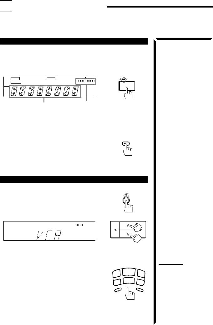
Turning the Power On and Off
On the front panel:
To turn on the power, press POWER.
The STANDBY lamp goes off. The name of the current source (or station frequency) appears on the display.
MUTE TUNED |
SLEEP SEA |
3D-PHONIC L |
R |
|
|
|
STANDBY |
AUTO STEREO PRO LOGIC 3CH LOGIC HALL |
LOUDNESS |
VOLUME |
|
DAP |
POWER |
|
|
CH- |
MHz |
kHz |
Current source name appears |
Current volume |
|
level is shown here |
To turn off the power, press POWER again.
The STANDBY lamp lights up.
From the remote control:
To turn on the power, press AUDIO. |
AUDIO |
The STANDBY lamp goes off. The name of the current |
|
source (or station frequency) appears on the display. |
|
To turn off the power, press AUDIO again.
The STANDBY lamp lights up.
Selecting the Source to Play
On the front panel:
1.Press SOURCE so that the Control %/ fibuttons work for selecting the source.
The lamp above the button lights up.
2.Press Control %/ fiuntil the source name you want appears on the display.
VOLUME
From the remote control:
Press one of the source buttons directly.
TUNER/BAND* |
Listen to the radio. |
|
Each time you press the button, the band |
|
alternates between FM and AM. |
CD* |
Listen to the CD player. |
TAPE* |
Listen to the cassette deck. |
TV SOUND |
Listen to TV sounds. |
VCR |
View the playback picture from the VCR. |
DVD |
Play back a stereo digital video disc. |
PHONO* |
Listen to a record. |
DVD MULTI |
Play back a digital video disc using the |
|
analog discrete output mode (5.1 CH |
|
reproduction) on the DVD player. |
SOURCE
CD
TUNER/ |
|
BAND |
|
TV |
VCR |
|
|
SOUND |
|
PHONO |
|
TAPE |
|
DVD |
|
DVD |
MULTI |
|
|
Notes:
•When you press one of the source buttons on the remote control marked with an asterisk (*), the receiver automatically turns on.
•When connecting this receiver and the DVD player by using the AV COMPU LINK cable, “DVD MULTI” is always selected when you start playing a disc of 5.1 ch surround. You can change it to “DVD” after playback starts.
14
 Loading...