


 Loading...
AUDIO/VIDEO CONTROL RECEIVER
RX-5030VBK
D I G I T A L
P R O L O G I C 
RX-5030V AUDIO/VIDEO CONTROL RECEIVER
INSTRUCTIONS
For Customer Use:
Enter below the Model No. and Serial No. which are located either on the rear, bottom or side of the cabinet. Retain this information for future reference.
Model No.
Serial No.
LVT0984-011A
[UJ]
Warnings, Cautions, and Others
Caution –– STANDBY/ON  switch!
Disconnect the mains plug to shut the power off completely. The STANDBY/ON  switch in any position does not disconnect the mains line. The power can be remote controlled.
CAUTION
To reduce the risk of electrical shocks, fire, etc.:
1.Do not remove screws, covers or cabinet.
2.Do not expose this appliance to rain or moisture.
CAUTION
•Do not block the ventilation openings or holes.
(If the ventilation openings or holes are blocked by a newspaper or cloth, etc., the heat may not be able to get out.)
•Do not place any naked flame sources, such as lighted candles, on the apparatus.
•When discarding batteries, environmental problems must be considered and local rules or laws governing the disposal of these batteries must be followed strictly.
•Do not expose this apparatus to rain, moisture, dripping or splashing and that no objects filled with liquids, such as vases, shall be placed on the apparatus.
G-1
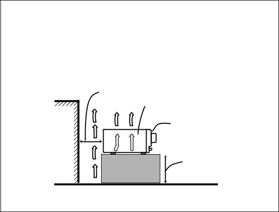
Caution: Proper Ventilation
To avoid risk of electric shock and fire and to protect from damage.
Locate the apparatus as follows:
Front: |
No obstructions open spacing. |
Sides: |
No obstructions in 10 cm from the sides. |
Top: |
No obstructions in 10 cm from the top. |
Back: |
No obstructions in 15 cm from the back. |
Bottom: |
No obstructions, place on the level surface. |
In addition, maintain the best possible air circulation as illustrated.
Spacing 15 cm or more
RX-5030VBK
Front
Wall or obstructions
Stand height 15 cm or more
Floor
G-2
Before Installation
Precautions
General precautions
•DO NOT insert any metal object into the unit.
•DO NOT disassemble the unit or remove screws, covers, or cabinet.
•DO NOT expose the unit to rain or moisture.
Locations
•Install the unit in a location that is level and protected from moisture.
•The temperature around the unit must be between –5˚C and 35˚C.
•Make sure there is good ventilation around the unit. Poor ventilation could cause overheating and damage the unit.
Handling the unit
•DO NOT touch the power cord with wet hands.
•DO NOT pull on the power cord to unplug the cord. When unplugging the cord, always grasp the plug so as not to damage the cord.
•Keep the power cord away from the connecting cords and the antenna. The power cord may cause noise or screen interference. Coaxial cable is recommended for the antenna connection, since such cable is well-shielded against interference.
•When a power failure occurs, or when you unplug the power cord, the preset settings such as preset FM or AM channels and sound adjustments may be erased within a few days.
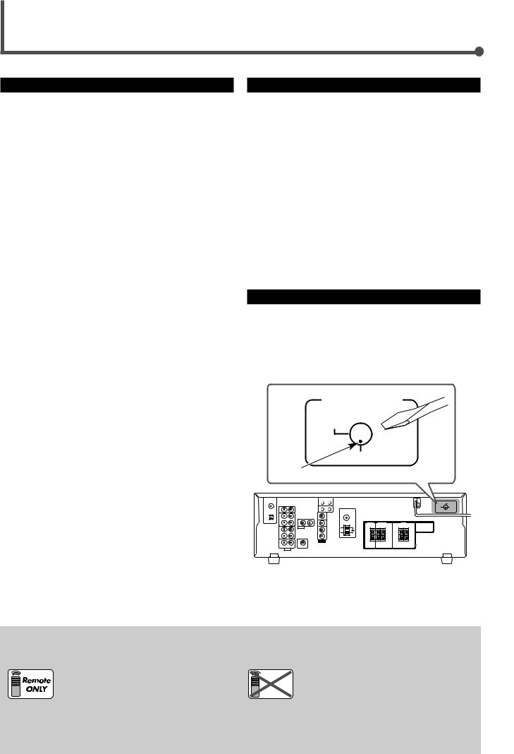
This mark indicates that ONLY the remote control CAN be used for the operation explained.
Checking the Supplied Accessories
Check to be sure you have all of the following supplied accessories. The number in parentheses indicates the quantity of each piece supplied.
•Remote control (1)
•Batteries (2)
•AM loop antenna (1)
•FM antenna (1)
•AC Plug Adaptor (1)
If anything is missing, contact your dealer immediately.
Setting the Voltage Selector Switch
Before connections, always do the following first if necessary.
Select the correct voltage in VOLTAGE SELECTOR on the rear by using a screw driver. Check to be sure if the voltage mark is set to the voltage for your area where this unit plugs in.
VOLTAGE
 110V
110V
220V

 127V
127V
230-240V
Voltage mark
|
This mark indicates that the remote control |
Remote CANNOT be used for the operation explained. |
|
NOT |
Use the buttons on the front panel. |
|
|
1

Table of Contents
Parts Identification ...................................... |
3 |
Getting Started........................................... |
5 |
Connecting the AM and FM Antennas ............................. |
5 |
Connecting the Speakers and Subwoofer ........................ |
6 |
Connecting Audio/Video Components .............................. |
7 |
Analog Connections ................................................................. |
7 |
Digital Connections .................................................................. |
9 |
Connecting the Power Cord ............................................. |
9 |
Putting Batteries in the Remote Control ........................... |
9 |
Basic Operations ....................................... |
10 |
Turning On the Power ..................................................... |
10 |
Selecting the Source to Play .......................................... |
10 |
Changing the Source Name ........................................... |
10 |
Selecting Different Sources for Picture and Sound ........ |
11 |
Adjusting the Volume ...................................................... |
11 |
Listening with Headphones Only .................................... |
11 |
Turning Off the Sound Temporarily—Muting ................... |
12 |
Changing the Display Brightness—DIMMER ................. |
12 |
Turning Off the Power with the Sleep Timer ................... |
12 |
Basic Settings........................................... |
13 |
Basic Settings Using MULTI JOG Dial ........................... |
13 |
Setting the Speaker Information ............................................ |
13 |
Selecting the Digital Input Terminals—DIGITAL IN ................ |
14 |
Selecting the Analog or Digital Input Mode .................... |
15 |
Sound Adjustments.................................... |
16 |
Attenuating the Input Signal ........................................... |
16 |
Turning Off the Subwoofer .............................................. |
16 |
Sound Adjustments Using MULTI JOG Dial ................... |
17 |
Sound Adjustments Using Remote Control .................... |
18 |
Adjusting Speaker Output Levels Using Test Tone ................. |
18 |
Adjusting Subwoofer Output Level ......................................... |
19 |
Tuner Operations ....................................... |
20 |
Setting the AM Tuner Interval Spacing ........................... |
20 |
Tuning in to Stations Manually ........................................ |
20 |
Using Preset Tuning ....................................................... |
20 |
Storing the Preset Stations .................................................... |
20 |
Tuning in to a Preset Station .................................................. |
21 |
Selecting the FM Reception Mode ................................. |
21 |
Creating Realistic Sound Fields ................... |
22 |
Using Surround Modes ................................................... |
24 |
Using DSP Modes .......................................................... |
25 |
COMPU LINK Remote Control System ......... |
26 |
AV COMPU LINK Remote Control System .... |
27 |
Operating JVC’s Audio/Video |
|
Components .......................................... |
29 |
Operating Audio Components ........................................ |
29 |
Operating Video Components ........................................ |
31 |
Operating Other Manufacturers’ Video |
|
Equipment ............................................ |
32 |
Troubleshooting ......................................... |
34 |
Specifications ............................................ |
35 |
2
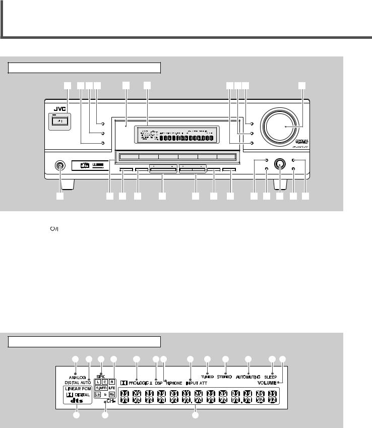
Parts Identification
|
Front Panel |
|
|
|
|
|
|
|
|
|
|
1 234 |
5 |
6 |
|
|
|
789 |
|
|
p |
|
|
|
|
|
|
|
|
|
MASTER VOLUME |
|
|
|
|
|
RX–5032V AUDIO/VIDEO CONTROL RECEIVER |
|
|
|
|
||
|
STANDBY |
|
|
|
|
|
|
|
|
|
|
SURROUND |
|
|
|
|
|
DIMMER |
|
|
|
|
STANDBY/ON |
|
|
|
|
|
|
|
|
|
|
DSP |
|
|
|
|
|
INPUT DIGITAL |
|
|
|
|
SURROUND/DSP |
|
|
|
|
|
INPUT ANALOG |
|
|
|
|
OFF |
|
|
|
|
|
|
|
|
|
|
|
|
|
|
|
|
INPUT ATT |
|
|
|
|
|
DVD |
VCR |
TV SOUND |
CD |
TAPE/CDR |
FM/AM |
|
|
|
|
|
|
|
|
|
|
|
SETTING |
MULTI JOG |
ADJUST |
|
|
|
|
|
|
SOURCE NAME |
|
|
|
|
PHONES |
D I G I T A L |
SPEAKERS |
SUBWOOFER OUT |
FM/AM TUNING |
FM/AM PRESET |
FM MODE |
MEMORY |
SET |
|
EXIT |
|
P R O L O G I C |
|
|
|
|
|
|
|
|
|
ON/OFF |
ON/OFF |
q |
w e r t |
y u i o ; a s d |
See pages in parentheses for details.
1 |
STANDBY/ON |
|
button and STANDBY lamp (10, 20) |
|
|||
2 |
SURROUND/DSP OFF button (24, 25) |
||
3 |
DSP button (25) |
||
4 |
SURROUND button (24) |
||
5 |
Remote sensor (9) |
||
6 |
Display (For details, see “Display” below.) |
||
7• INPUT ANALOG button (15)
•INPUT ATT (attenuator) button (16) 8 INPUT DIGITAL button (15)
9 DIMMER button (12)
p MASTER VOLUME control (11) q PHONES jack (11)
w • Source selection buttons (10)
DVD, VCR, TV SOUND, CD, TAPE/CDR, FM/AM
• SOURCE NAME button (10) e SPEAKERS ON/OFF button (11)
r SUBWOOFER OUT ON/OFF button (16) t FM/AM TUNING 5/∞ buttons (20)
y FM/AM PRESET 5/∞ buttons (20, 21) u FM MODE button (21)
i MEMORY button (20, 21) o SETTING button (13)
; SET button (13, 17)
a MULTI JOG dial (13, 17) s EXIT button (13, 17)
d ADJUST button (17)
Display |
|
|
1 2 3 4 5 67 8 9 0 - = ~ |
||
! |
@ |
# |
See pages in parentheses for details.
1 ANALOG indicator (15)
2 DIGITAL AUTO indicator (15)
3 SPK (speaker) indicator (11)
4 Speaker indicators and signal indicators (25)
5  PRO LOGIC II indicator (22, 24)
6 DSP indicator (23, 25)
7 H.PHONE indicator (11)
8 INPUT ATT (attenuator) indicator (16)
9 TUNED indicator (20)
0 STEREO indicator (20)
- AUTO MUTING indicator (21) = SLEEP indicator (12)
~ VOLUME indicator (12)
! Digital signal format indicators (15) @ CH– indicator (20)
# Main display
3
|
See pages in parentheses for details. |
|
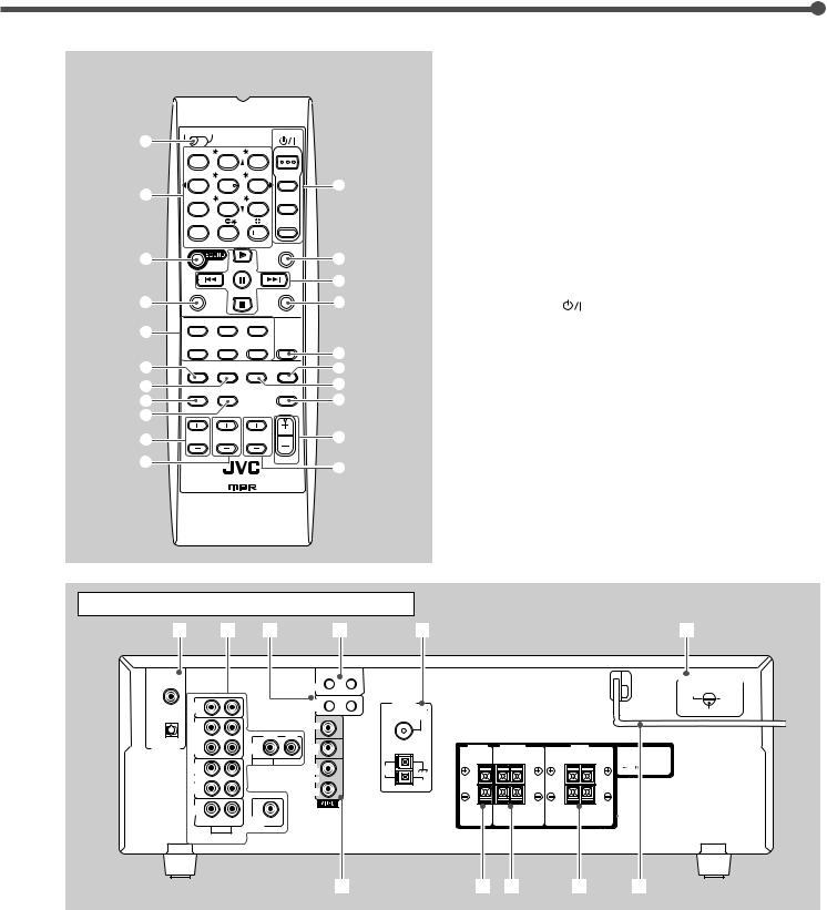
Remote Control |
||
1 TV/CATV selector (32) |
||
|
2• 10 keys for selecting preset channels (21)
• 10 keys for sound adjustment (18, 19)
|
TV |
CATV A/V CONTROL |
STANDBY/ON |
|
|
• 10 keys for operating audio/video components (29 – 33) |
|||
1 |
|
|
RECEIVER |
|
|
3 |
SOUND button (18, 19) |
||
|
TEST |
FRONT L |
FRONT R |
AUDIO |
|
||||
|
|
|
4 |
REC PAUSE button (30, 31, 33) |
|||||
|
|
1 |
2 |
3 |
|
|
|||
|
|
|
CENTER |
SUBWFR |
TV/CATV |
|
5 |
Source selection buttons (10) |
|
2 |
|
4 |
5 |
6 |
|
= |
|
TAPE/CDR, CD, DVD, FM/AM, TV SOUND, VCR |
|
|
MENU |
SURR L |
SURR R |
VCR |
|
|
|||
|
|
|
|
|
|
6 |
FM MODE button (21) |
||
|
|
7/P |
8 |
9 |
|
|
|||
|
|
ENTER |
LEVEL |
DVD |
|
7 |
SURROUND button (24) |
||
|
|
|
|
|
|
|
|
|
|
|
|
10 |
0 |
10 |
|
|
8 |
DIMMER button (12) |
|
|
|
RETURN |
TA/NEWS/INFO 100 |
SLEEP |
|
||||
|
|
|
|
|
|
9 |
TV/VIDEO button (31) |
||
3 |
|
|
|
|
|
~ |
|||
|
|
REW |
FF |
|
0 |
VCR CH (channel) +/– buttons (31, 33) |
|||
|
|
|
|
|
|
! |
|||
|
|
|
|
|
|
- TV/CATV CH (channel) +/– buttons (31, 32) |
|||
4 |
REC PAUSE |
|
CD-DISC |
@ |
|||||
|
|
|
|
|
= STANDBY/ON |
buttons (10, 31 – 33) |
|||
|
TAPE/CDR |
CD |
DVD |
|
|
|
AUDIO, TV/CATV, VCR, DVD |
||
5 |
|
|
|
|
ANALOG |
|
~ SLEEP button (12) |
|
|
|
|
FM/AM |
TV SOUND |
VCR |
|
|
|||
|
|
/DIGITAL |
# |
! Operating buttons for audio/video components |
|||||
6 |
|
|
|
|
SURROUND |
||||
FM MODE SURROUND |
DSP |
$ |
|
3, 8, 7, ¢/4, FF/REW (30, 31, 33) |
|||||
/DSP |
|
||||||||
7 |
|
|
|
|
OFF |
% |
@ CD-DISC button (30) |
||
DIMMER |
TV/VIDEO |
|
MUTING |
||||||
8 |
|
|
|
|
|
^ |
# ANALOG/DIGITAL button (15) |
||
9 |
|
|
|
|
|
|
$ SURROUND/DSP OFF button (24, 25) |
||
0 |
VCR CH |
TV/CATV CH |
TV VOLUME |
|
& |
% DSP button (25) |
|
||
|
|
|
|
|
|
||||
- |
|
|
|
|
VOLUME |
|
^ MUTING button (12) |
||
|
|
|
|
* |
& VOLUME +/– button (11) |
||||
|
|
|
|
|
|
||||
|
REMOTE CONTROL |
|
|
|
* TV VOLUME +/– buttons (31) |
||||
|
|
|
|
|
|
|
|||
Rear Panel
1 |
2 |
3 |
4 |
5 |
6 |
DIGITAL 1 |
AV |
(DVD) |
COMPU LINK |
|
|
CD |
|
|
COMPU LINK-4 |
ANTENNA |
|
|
|
IN |
|
|
(SYNCHRO) |
FM 75 |
|
|
DIGITAL 2 ( CD ) |
|
|
|
|
COAXIAL |
|
|
|
OUT |
|
|
MONITOR |
|
|
|
|
(REC) |
|
|
OUT |
|
|
|
|
TAPE |
|
RIGHT |
LEFT |
|
|
|
|
/CDR |
|
DVD |
DVD |
|
|
|
DIGITAL IN |
IN |
|
|
|
|
||
|
(PLAY) |
|
IN |
IN |
|
|
|
|
OUT |
|
AUDIO |
OUT |
|
|
|
|
|
|
AM |
|
|
||
|
(REC) |
|
|
(REC) |
LOOP |
|
|
|
VCR |
|
|
VCR |
AM |
|
|
|
IN |
|
|
IN |
|
|
|
|
|
|
EXT |
|
|
||
|
(PLAY) |
|
RIGHT |
(PLAY) |
|
|
|
|
|
|
|
|
|
|
|
TV SOUND |
|
|
|
|
|
|
|
|
IN |
|
|
|
|
|
|
|
RIGHT |
LEFT |
SUBWOOFER |
|
|
|
|
|
AUDIO |
OUT |
|
|
|
|
|
|
|
|
|
|
|
||
|
|
|
|
7 |
8 9 |
p |
q |
VOLTAGE SELECTOR |
 110V
110V
220V
127V
230 - 240V
See pages in parentheses for details.
1DIGITAL IN terminals (9)
•Coaxial: DIGITAL 1 (DVD)
•Optical: DIGITAL 2 (CD)
2 Audio input/output terminals (6 – 8)
• Input: CD IN, TAPE/CDR IN, VCR IN, TV SOUND IN, DVD IN
•Output: TAPE/CDR OUT, VCR OUT
•SUBWOOFER OUT
3 COMPU LINK-4 (SYNCHRO) terminals (26)
4 |
AV COMPU LINK terminals (27) |
5 |
FM/AM ANTENNA terminals (5) |
6 |
Voltage selector (1) |
7 |
VIDEO (composite video) input/output terminals (8) |
|
• Input: DVD IN, VCR IN |
|
• Output: MONITOR OUT, VCR OUT |
8 |
CENTER SPEAKER terminals (6) |
9 |
SURROUND SPEAKERS terminals (6) |
p FRONT SPEAKERS terminals (6) q AC power cord (9)
4

Getting Started
Connecting the AM and FM Antennas
AM antenna connection
Connect the supplied AM loop antenna to the AM LOOP terminals.
Turn the loop until you have the best reception.
•If the reception is poor, connect an outdoor single vinylcovered wire (not supplied) to the AM EXT terminal. (Keep the AM loop antenna connected.)
FM antenna connection
Connect the supplied FM antenna to the FM 75 Ω COAXIAL terminal as a temporary measure.
Extend the supplied FM antenna horizontally.
•If the reception is poor, connect an outdoor FM antenna (not supplied). Before attaching a 75 Ω coaxial cable with a connector, disconnect the supplied FM antenna.
7 How to connect the AM antenna cord
1 |
2 |
3 |
1Open the terminal.
2Insert the AM antenna cord.
3Close the terminal.
Notes:
•If the AM loop antenna wire is covered with vinyl, remove the vinyl by twisting it as shown to the right.
•Make sure the antenna conductors do not touch any other terminals, connecting cords, or power cord. This could cause poor reception.
Rear panel
•If FM reception is poor, connect an outdoor FM antenna.
75 FMCOAXIAL
75 Ω coaxial cable with a |
FM |
|
75 |
connector (not supplied) |
COAXIAL |
|
AM
LOOP
AM
EXT
AM loop antenna
(supplied)
FM antenna (supplied)
Extend the supplied FM antenna horizontally.
If AM reception is poor, connect outdoor single vinyl-covered wire
(not supplied).
Snap the tabs on the loop into the slots of the base to assemble the AM loop antenna.
5

Connecting the Speakers and Subwoofer
You can connect five speakers—a pair of front speakers, a center speaker, and a pair of surround speakers—and a subwoofer.
CAUTION:
Use speakers with a SPEAKER IMPEDANCE as indicated by the speaker terminals.
7 Connection diagram
7 Speaker layout diagram
|
Center |
|
speaker |
Left front |
Right front |
speaker |
Subwoofer speaker |
Left |
Right |
surround |
surround |
speaker |
speaker |
|
|
|
|
|
|
: |
|
|
|
|
|
CAUTION |
IMPEDANCE |
|
|
|
|
|
SPEAKER16 |
|
|
|
|
|
FRONT |
8 |
|
|
|
|
|
SPEAKERS |
+ |
|
|
|
|
|
|
|
|
|
|
|
SURROUND |
|
|
To left |
|
|
|
SPEAKERS |
|
|
|
|
|
|
|
|
front speaker |
|
|
|
|
CENTER |
|
|
|
|
|
|
SPEAKER |
|
|
|
|
|
|
+ |
|
|
|
|
Cable with RCA pin |
|
– |
|
|
To left surround |
|
|
|
|
|
||
|
plugs (not supplied) |
|
|
|
|
speaker |
|
|
To center speaker |
|
|
|
|
SUBWOOFER |
To subwoofer |
To right front speaker |
|
|
|
|
OUT |
input |
|
|
|
||
|
|
|
|
|
||
|
|
To right |
surround speaker |
|
|
|
|
|
Powered |
|
|
|
|
|
|
subwoofer |
|
|
|
|
7 How to connect speaker cords
For each speaker, connect the (+) and (–) terminals on the rear panel to the (+) and (–) terminals marked on the speakers.
1 |
2 |
3 |
1
2
+ |
+ |
– |
– |
1Twist and remove the insulation at the end of each speaker cord.
2Open the terminal (1), then insert the speaker cord (2).
3Close the terminal.
7 How to connect the subwoofer
Connect the input jack of a powered subwoofer to the SUBWOOFER OUT jack on the rear panel, using a cable with RCA pin plugs (not supplied).
• Refer also to the manual supplied with your subwoofer.
By connecting a subwoofer, you can enhance the bass or reproduce the original LFE signals recorded in the digital software.
Since bass sound is non-directional, you can place a subwoofer wherever you like. Normally place it in front of you.
After connecting the front, center, surround speakers and/ or a subwoofer, set the speaker setting information properly to obtain the best possible Surround effects with your listening conditions. For details, see pages 13 and 14.
•“NO” for the subwoofer and “LARGE” for the front speakers, “SMALL” for the center and surround speakers are initial settings.
6
Getting Started
Connecting Audio/Video Components
Turn the power off to all components before making connections.
You can connect the following audio/video components to this receiver. Refer also to the manuals supplied with your components.
•Audio Components: CD player* and Cassette deck (or CD recorder*)
•Video Components: VCR, TV*, and DVD player*
*You can connect these components using the methods described in “Analog Connections” (below) and/or in “Digital Connections” (see page 9).
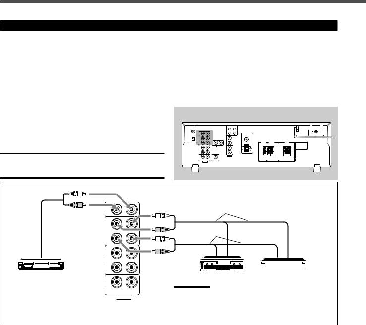
Analog Connections
Audio component connections
Rear panel
Use cables with RCA pin plugs (not supplied).
Connect the white plug to the audio left jack and the red plug to the audio right jack.
CAUTION:
If you connect a sound-enhancing device such as a graphic equalizer between the source components and this receiver, the sound output through this receiver may be distorted.
L
R
To audio output
CD player
CD
IN
OUT (REC)
TAPE /CDR
IN (PLAY)
OUT (REC)
VCR
IN (PLAY)
TV SOUND
IN
RIGHT LEFT
AUDIO
To audio input
L
R
To audio output
L
R
|
|
|
|
|
|
|
|
|
|
|
|
|
|
|
|
Cassette deck |
|
CD recorder |
|||||||||||
|
|
|
|
|||||||||||
Note:
You can connect either a cassette deck or a CD recorder to the
TAPE/CDR jacks. When connecting a CD recorder to the TAPE/ CDR jacks, change the source name to CDR so that “CDR” appears on the display when selected as the source. See page 10 for details.
If your audio components have a COMPU LINK jack
See also page 26 for detailed information about the connections with the COMPU LINK remote control system.
7
Video component connections
Use cables with RCA pin plugs (not supplied).
Connect the white plug to the audio left jack, the red plug to the audio right jack, and the yellow plug to the video jack.
Rear panel
VCR
VCR
A 
 B
B 

 C
C 
 D
D
|
CD |
|
|
|
IN |
|
|
|
OUT |
MONITOR |
|
|
(REC) |
OUT |
|
L |
TAPE |
||
|
|||
|
/CDR |
DVD |
|
|
IN |
||
|
(PLAY) |
IN |
|
R |
OUT |
OUT |
|
|
|||
|
(REC) |
(REC) |
|
|
VCR |
VCR |
|
|
IN |
IN |
|
R |
(PLAY) |
(PLAY) |
|
|
|
TV SOUND
IN
L RIGHT LEFT
AUDIO
Å To left/right audio input ı To left/right audio output Ç To video input
Î To video output
TV
TV
A |
|
|
|
|
|
B |
|
|
|
|
|
||
|
|
|
|
|
||
|
|
|
|
|
|
|
|
|
|
|
|
|
|
|
|
|
|
|
|
|
CD
IN
|
OUT |
MONITOR |
|
(REC) |
OUT |
|
TAPE |
|
|
|
|
|
/CDR |
DVD |
|
IN |
|
|
(PLAY) |
IN |
|
OUT |
OUT |
|
(REC) |
(REC) |
|
VCR |
VCR |
R |
IN |
IN |
(PLAY) |
(PLAY) |
TV SOUND 
IN
L |
RIGHT |
LEFT |
AUDIO |
||
Å To audio output ı To video input
DVD
DVD player
DVD |
B
A
R |
|
MONITOR |
RIGHT |
OUT |
|
|
LEFT |
|
|
DVD |
DVD |
|
IN |
IN |
AUDIO
L
OUT (REC)
VCR
IN (PLAY)
Å To audio output ı To video output
To use software encoded with Dolby Digital or DTS Digital Surround, connect the DVD player using one of the DIGITAL IN terminals (see page 9).
8
Getting Started
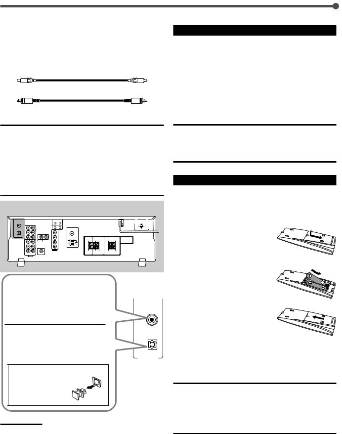
Digital Connections
This receiver is equipped with two DIGITAL IN terminals—one digital coaxial terminal and one digital optical terminal.
You can connect any component to one of the digital terminals using a digital coaxial cable (not supplied) or digital optical cable (not supplied).
Digital coaxial cable
Digital optical cable
IMPORTANT:
•When connecting a video component using the digital terminal, you also need to connect it to the video jack on the rear. Without connecting it to the video jack, you cannot view the playback picture.
•After connecting the components using the DIGITAL IN terminals, correctly set the following if necessary:
–Set the digital input (DIGITAL IN) terminal setting correctly. For details, see “Selecting the Digital Input Terminals—DIGITAL IN” on page 14.
–Select the digital input mode correctly. For details, see “Selecting the Analog or Digital Input Mode” on page 15.
Rear panel
When the component has a digital coaxial output terminal, connect it to the DIGITAL 1 (DVD) terminal, using
DIGITAL 1
the digital coaxial cable (not (DVD) supplied).
When the component has a digital
optical output terminal, connect it to |
( CD ) |
|
|
||
the DIGITAL 2 (CD) terminal, using |
|
|
the digital optical cable (not |
IN |
|
supplied). |
||
|
||
Before connecting a digital |
|
|
optical cable, unplug the |
|
|
protective plug. |
|
Notes:
•When shipped from the factory, the DIGITAL IN terminals have been set for use with the following components:
–DIGITAL 1 (coaxial): For DVD player
–DIGITAL 2 (optical): For CD player
•When you want to operate the CD player or CD recorder using the COMPU LINK remote control system, connect the target component also as described in “Analog Connections” (see page 7).
•When you want to operate the DVD player using the AV COMPU LINK remote control system, connect the DVD player also as described in “Analog Connections” (see page 8).
Connecting the Power Cord
Before plugging the power cord into an AC outlet, make sure that all connections have been made.
Plug the power cord into an AC outlet.
Keep the power cord away from the connecting cables and the antenna. The power cord may cause noise or screen interference. We recommend that you use a coaxial cable to connect the antenna, since it is well-shielded against interference.
CAUTIONS:
•Do not plug in before setting the voltage selector switch on the rear of the unit and all connection procedures are complete.
•Do not touch the power cord with wet hands.
•Do not pull on the power cord to unplug the cord. When unplugging the cord, always grasp the plug so as not to damage the cord.
Putting Batteries in the Remote Control
Before using the remote control, put two supplied batteries first.
•When using the remote control, aim the remote control directly at the remote sensor on the front panel.
1 On the back of the remote control, remove the battery cover.
2 Insert batteries.
• Make sure to match the polarity:
(+) to (+) and (–) to (–).
3 Replace the cover.
If the range or effectiveness of the remote control decreases, replace the batteries. Use two R6P(SUM-3)/AA(15F) type drycell batteries.
CAUTION:
Follow these precautions to avoid leaking or cracking cells:
•Place batteries in the remote control so they match the polarity:
(+) to (+) and (–) to (–).
•Use the correct type of batteries. Batteries that look similar may differ in voltage.
•Always replace both batteries at the same time.
•Do not expose batteries to heat or flame.
9
Loading...