


COMPACT COMPONENT SYSTEM
CA-MXJ850R
|
SOUND |
S.A.BASS SLEEP |
||
|
MODE |
|||
DISPLAY |
PTY/EON |
|
– SELECT + |
|
MODE |
|
|||
TAPE A |
PRO LOGIC |
3 STEREO |
TEST TONE |
|
TAPE B |
– CENTERLEVEL |
+ |
CENTER MODE |
|
REC PAUSE |
– LEVELREAR |
+ |
DELAY TIME |
|
SHIFT |
L BALANCE R |
FM MODE |
||
+
FADE
MUTING
–
RM–SMXJ75R REMOTE CONTROL
STANDBY |
|
|
CD3 |
|
COMPACT |
|
CD2 |
|
DIGITAL AUDIO |
|
|
|
|
|
CD1 |
|
PLAY & EXCHANGE |
|
|
|
|
VOLUME |
|
|
|
+ |
|
PHONES |
|
– |
|
PANEL |
|
|
|
OPEN / CLOSE |
|
|
|
TAPE |
|
CD |
|
COMPU |
|
|
|
PLAY |
|
|
|
CONTROL |
|
|
COMPACT |
AUX |
|
FM/ AM |
DIGITAL AUDIO
PLAY |
REC/PLAY |
AUTO REVERSE |
AUTO REVERSE |
EJECT |
EJECT |
INSTRUCTIONS
For Customer Use:
Enter below the Model No. and Serial No. which are located either on the rear, bottom or side of the cabinet. Retain this information for future reference.
Model No.
Serial No.
GVT0044-008A
[ B ]
Cover.CA-MXJ850R[B]/f |
1 |
00.4.21, 4:31 PM |
Warnings, Cautions and Others
IMPORTANT for the U.K.
DO NOT cut off the mains plug from this equipment. If the plug fitted is not suitable for the power points in your home or the cable is too short to reach a power point, then obtain an appropriate safety approved extension lead or consult your dealer.
BE SURE to replace the fuse only with an identical approved type, as originally fitted.
If nontheless the mains plug is cut off ensure to remove the fuse and dispose of the plug immediately, to avoid a possible shock hazard by inadvertent connection to the mains supply.
If this product is not supplied fitted with a mains plug then follow the instructions given below:
IMPORTANT:
DO NOT make any connection to the terminal which is marked with the letter E or by the safety earth symbol or coloured green or green-and-yellow.
The wires in the mains lead on this product are coloured in accordance with the following code:
Blue : Neutral Brown : Live
As these colours may not correspond with the coloured markings identifying the terminals in your plug proceed as follows:
The wire which is coloured blue must be connected to the terminal which is marked with the letter N or coloured black.
The wire which is coloured brown must be connected to the terminal which is marked with the letter L or coloured red.
IF IN DOUBT - CONSULT A COMPETENT ELECTRICIAN.
CAUTION
To reduce the risk of electrical shocks, fire, etc.:
1.Do not remove screws, covers or cabinet.
2.Do not expose this appliance to rain or moisture.
Caution ––
 switch!
Disconnect the mains plug to shut the power off completely. The  switch in any position does not disconnect the mains line. The
power can be remote controlled.
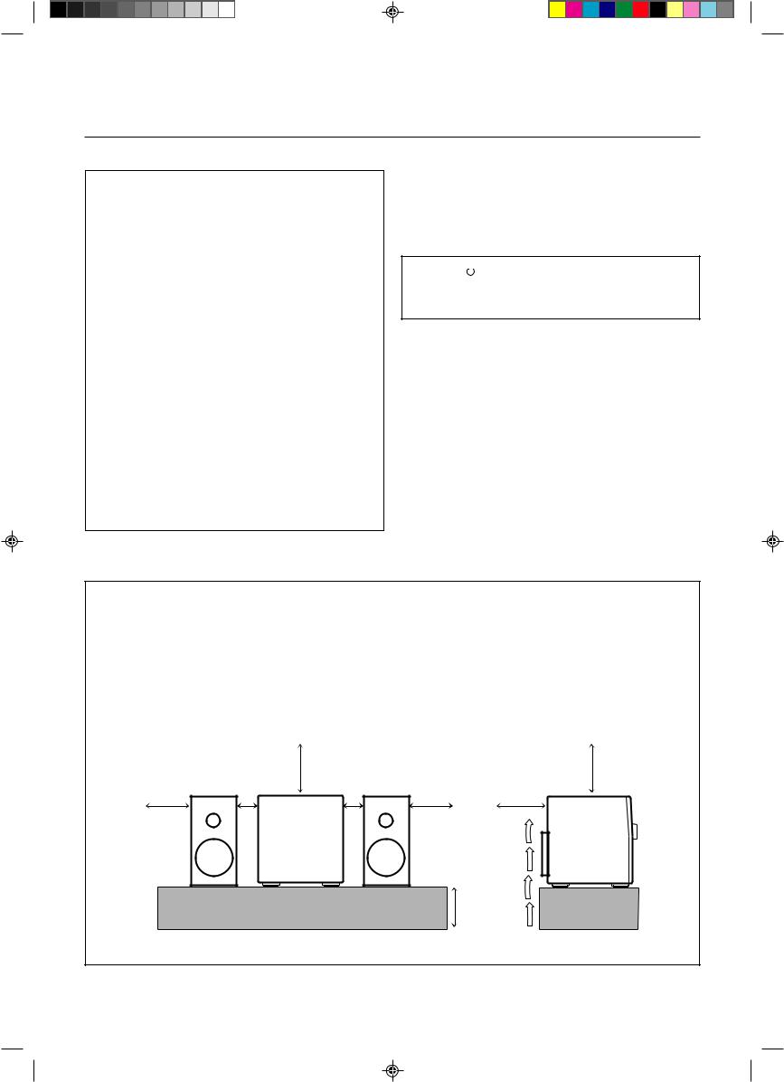
Caution: Proper Ventilation
To avoid risk of electric shock and fire, and to prevent damage, locate the apparatus as follows: 1 Front:
No obstructions and open spacing. 2 Sides/ Top/ Back:
No obstructions should be placed in the areas shown by the dimensions below. 3 Bottom:
Place on the level surface. Maintain an adequate air path for ventilation by placing on a stand with a height of 10 cm or more.
Front view |
|
Side view |
|
|
|
15 cm |
|
15 cm |
1 cm |
1 cm |
|
15 cm |
15 cm |
15 cm |
CA-D3S |
|
CA-D3S |
CA-MXJ850R |
|
CA-MXJ850R |
10 cm
– G-1 –
Cover.CA-MXJ850R[B]/f |
2 |
00.4.21, 4:31 PM |
IMPORTANT FOR LASER PRODUCTS
REPRODUCTION OF LABELS
1 CLASSIFICATION LABEL, PLACED ON REAR ENCLOSURE |
2 WARNING LABEL, PLACED INSIDE THE UNIT |
CLASS 1
LASER PRODUCT
DANGER: Invisible laser radiation when open and interlock failed or defeated.
AVOID DIRECT EXPOSURE TO BEAM. (e)
VARNING: Osynlig laserstrålning när denna del är öppnad och spärren är urkopplad. Betrakta ej strålen. (s)
ADVARSEL: Usynlig laserstråling ved åbning, når sikkerhedsafbrydere er ude af funktion. Undgå udsættelse for stråling (d)
VARO: Avattaessa ja suojalukitus ohitettaessa olet alttiina näkymättömälle lasersäteilylle. Älä katso säteeseen. (f)
1.CLASS 1 LASER PRODUCT
2.DANGER: Invisible laser radiation when open and interlock failed or defeated. Avoid direct exposure to beam.
3.CAUTION: Do not open the top cover. There are no user serviceable parts inside the Unit; leave all servicing to qualified service personnel.
– G-2 –
Cover.CA-MXJ850R[B]/f |
3 |
00.4.21, 4:31 PM |
Introduction
We would like to thank you for purchasing one of our JVC products. Before operating this unit, read this manual carefully and thoroughly to obtain the best possible performance from your unit, and retain this manual for future reference.
About This Manual
This manual is organized as follows:
•The manual mainly explains operations using the buttons and controls on the unit. You can also use the buttons on the remote control if they have the same or similar names (or marks) as those on the unit.
If operation using the remote control is different from that using the unit, it is then explained.
•Basic and common information that is the same for many functions is grouped in one place, and is not repeated in each procedure. For instance, we do not repeat the information about turning on/off the unit, setting the volume, changing the sound effects, and others, which are explained in the section “Common Operations” on pages 10 to 12.
•The following marks are used in this manual:
Gives you warnings and cautions to prevent from a damage or risk of fire/electric shock. Also gives you information which is not good for obtaining the best possible performance from the unit.
Gives you information and hints you had better know.
Precautions
Installation
•Install in a place which is level, dry and neither too hot nor too cold — between 5˚C (41˚F) and 35˚C (95˚F).
•Install the unit in a location with adequate ventilation to prevent internal heat built-up in the unit.
•Leave sufficient distance between the unit and the TV.
•Keep the speakers away from the TV to avoid interference with TV.
DO NOT install the unit in a location near heat 
 sources, or in a place subject to direct sunlight,
excessive dust or vibration.
Power sources
• When unplugging from the wall outlet, always pull the plug, not the AC power cord.
DO NOT handle the AC power cord with wet hands.
Moisture condensation
Moisture may condense on the lens inside the unit in the following cases:
•After starting heating in the room
•In a damp room
•If the unit is brought directly from a cold to a warm place Should this occur, the unit may malfunction. In this case, leave the unit turned on for a few hours until the moisture evaporates, unplug the AC power cord, and then plug it in again.
Others
•Should any metallic object or liquid fall into the unit, unplug the unit and consult your dealer before operating any further.
•If you are not going to operate the unit for an extended period of time, unplug the AC power cord from the wall outlet.
DO NOT disassemble the unit since there are no user serviceable parts inside.
If anything goes wrong, unplug the AC power cord and consult your dealer.
– 1 –
EN01-09.MXJ850R[B]/f |
1 |
00.4.21, 4:31 PM |
Contents
Location of the Buttons and Controls ....................... |
3 |
Front Panel ................................................................. |
4 |
Remote Control .......................................................... |
5 |
Getting Started ............................................................ |
6 |
Unpacking .................................................................. |
6 |
Putting the Batteries into the Remote Control ........... |
6 |
Connecting Antennas ................................................. |
6 |
Connecting Speakers .................................................. |
7 |
Connecting Other Equipment ..................................... |
8 |
Common Operations ................................................ |
10 |
Setting the Clock ...................................................... |
10 |
Turning On the Power and Selecting the Sources ....... |
10 |
Adjusting the Volume ............................................... |
11 |
Adjusting the Front Speaker Output Balance ........... |
11 |
Reinforcing the Bass Sound ..................................... |
11 |
Selecting the Sound Modes ...................................... |
11 |
Creating Your Own Sound Mode |
|
— Manual Mode ................................................. |
12 |
Listening to FM and AM (MW/LW) Broadcasts ... |
13 |
Tuning in a Station ................................................... |
13 |
Presetting Stations .................................................... |
13 |
Tuning in a Preset Station ........................................ |
13 |
Receiving FM Stations with RDS ............................ |
14 |
Changing the RDS Information ............................... |
14 |
Searching for Programs by PTY Codes |
|
(PTY Search) ...................................................... |
14 |
Switching to a Program Type of Your |
|
Choice Temporarily ............................................ |
15 |
Playing Back CDs ..................................................... |
16 |
Loading CDs ............................................................ |
16 |
Playing Back the Entire Discs |
|
— Continuous Play ............................................. |
16 |
Basic CD Operations ................................................ |
16 |
Programming the Playing Order of the Tracks |
|
— Program Play ................................................. |
17 |
Playing at Random — Random Play ....................... |
18 |
Repeating Tracks or CDs — Repeat Play ................ |
18 |
Prohibiting Disc Ejection — Tray Lock ................... |
18 |
Playing Back Tapes ................................................... |
19 |
Playing Back a Tape ................................................. |
19 |
Locating the Beginning of a Song — Music Scan ... |
19 |
Using Dolby Surround .............................................. |
20 |
Preparing for Dolby Surround .................................. |
20 |
Enjoying Playback with Dolby Surround ................ |
21 |
Recording .................................................................. |
22 |
Recording Tapes on Deck B ..................................... |
22 |
Dubbing Tapes .......................................................... |
23 |
CD Direct Recording ................................................. |
23 |
Auto Edit Recording .................................................. |
24 |
Using the Timers ....................................................... |
25 |
Using Daily Timer .................................................... |
25 |
Using Recording Timer ............................................ |
26 |
Using Sleep Timer .................................................... |
27 |
Timer Priority ........................................................... |
27 |
Additional Information ............................................ |
28 |
Maintenance .............................................................. |
28 |
Troubleshooting ........................................................ |
29 |
Specifications ............................................................. |
30 |
– 2 –
EN01-09.MXJ850R[B]/f |
2 |
00.4.21, 4:31 PM |

Location of the Buttons and Controls
Become familiar with the buttons and controls on your unit.
Powered Rolling Panel |
|
|
|
|
|
|
|
|
h |
|
i |
|
|
|
|
|
|
|
j |
||
|
|
o |
|
|
|
|
|
|
|
k |
PANEL |
|
|
|
PRESET |
|
|
TUNING |
|
|
|
OPEN / CLOSE |
|
REC |
|
|
|
|
PROGRAM |
|||
|
|
|
|
|
|
|
|
|||
|
|
START/STOP |
|
|
|
|
|
|
|
/ RANDOM |
|
|
; |
|
|
|
|
|
|
|
l |
|
|
|
REVERSE |
|
SEA CONTROL |
DEMO |
|
PRO LOGIC |
|
|
|
|
DUBBING |
MODE |
|
|
/ 3 STEREO |
EDIT |
|||
|
|
a |
|
CLOCK |
SET |
CANCEL |
SOUND |
|
/ |
|
|
|
|
/ TIMER |
MODE |
|
|||||
|
|
|
|
|
|
|
||||
Press PANEL OPEN/ |
CD REC START |
TAPE A/B |
DISPLAY |
|
|
|
|
S. A. BASS |
REPEAT |
|
CLOSE to open the panel. s |
|
|
– |
|
+ |
|
z |
|||
|
MODE |
PTY / EON |
SELECT |
|
||||||
To close the panel, press |
d |
|
|
|
|
|
|
|
x |
|
the button again. |
f |
|
|
|
|
|
|
|
c |
|
|
|
|
|
|
|
|
|
|
||
|
|
g |
|
|
|
|
|
|
|
v |
|
|
|
|
|
|
|
|
|
|
b |
1 |
|
|
|
|
|
|
|
|
|
q |
|
|
|
|
|
|
|
|
|
CD3 |
|
|
STANDBY |
|
|
|
|
|
|
|
|
|
2 |
|
COMPACT |
|
|
|
|
CD3 |
|
CD2 |
|
|
DIGITAL AUDIO |
|
|
|
|
|
w |
|||
|
|
|
|
|
|
|
CD2 |
|
|
|
|
|
|
|
|
|
|
|
CD1 |
|
|
|
|
|
|
|
|
|
|
|
|
|
3 |
|
PLAY & EXCHANGE |
|
|
|
|
CD1 |
|
|
|
4 |
|
|
|
|
|
|
|
|
|
|
5 |
|
|
|
|
|
|
VOLUME |
|
|
|
|
|
|
|
|
|
+ |
|
|
|
|
|
|
|
|
|
|
|
|
|
|
e |
|
PHONES |
|
|
|
|
|
– |
|
|
|
6 |
PANEL |
|
|
|
|
|
|
|
|
|
|
|
|
|
|
|
|
|
|
||
OPEN / CLOSE |
|
|
|
|
|
|
|
|
||
|
|
|
|
|
|
|
|
|
|
|
7 |
TAPE |
|
|
|
|
|
|
CD |
|
|
COMPU |
|
|
|
|
|
|
|
|
r |
|
PLAY |
|
|
|
|
|
|
|
|
||
|
CONTROL |
|
|
|
|
|
|
|
|
|
8 |
AUX |
|
|
|
|
|
|
FM/ AM |
|
t |
|
|
|
|
|
|
|
|
|
||
|
|
PLAY |
|
|
REC/PLAY |
|
|
|
|
|
9 |
|
AUTO REVERSE |
AUTO REVERSE |
|
|
|
y |
|||
|
|
|
|
|
|
|||||
|
|
|
EJECT |
EJECT |
|
|
|
|
|
|
p |
|
|
|
|
|
|
|
|
|
u |
|
|
|
|
– 3 – |
|
|
|
|
|
|
EN01-09.MXJ850R[B]/f |
3 |
00.4.21, 4:31 PM |
Continued 
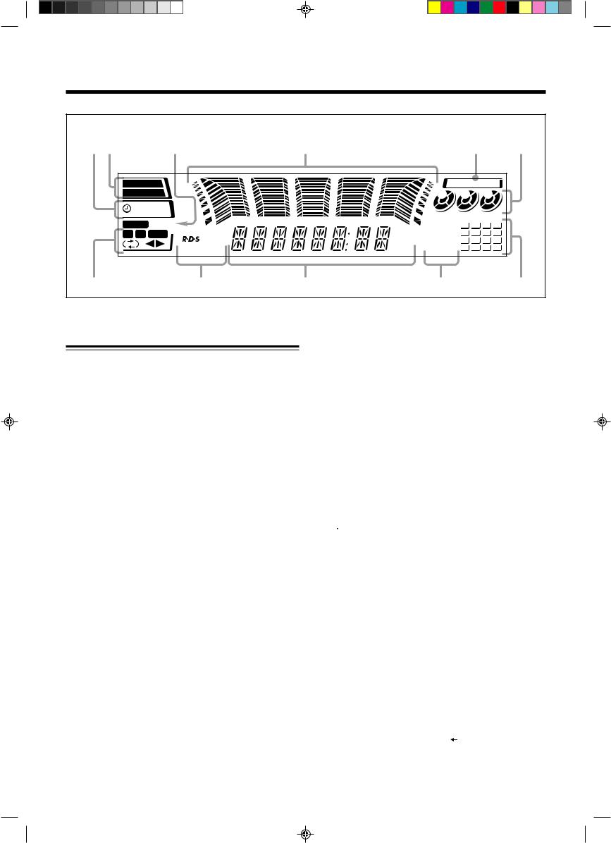
Display Window
1 2 |
3 |
4 |
5 |
6 |
PRO LOGIC |
|
SOUND MODE |
||||||
3 STEREO |
|
1 |
2 |
|
3 |
|
||
|
SLEEP |
|
|
|
|
|
|
|
|
DAILY REC |
|
|
|
|
|
|
|
STEREO MONO |
|
REPEAT |
1 |
2 |
3 |
4 |
||
A |
B |
REC |
|
ALL 1CD |
5 |
6 |
7 |
8 |
|
|
EON |
kHz |
PROGRAM |
9 |
10 |
11 |
12 |
|
|
TA NEWS INFO |
MHz |
RANDOM |
13 14 |
15 |
16 |
|
q |
p |
9 |
8 |
7 |
See pages in the parentheses for details.
Front Panel
1 Disc trays
2  (standby/on) button and STANDBY lamp (10) 3 Display window
4 Remote sensor
5PANEL OPEN/CLOSE button (10)
Pressing this button also turns on the unit.
6 PHONES jack (11)
7TAPE 23button and lamp (19)
Pressing this button also turns on the unit.
8AUX button and lamp (10)
Pressing this button also turns on the unit.
9 Deck A cassette holder (19)
p 0EJECT button for deck A (19)
q0(CD tray open/close) buttons (16)
Pressing one of these buttons also turns on the unit.
wDisc number buttons and lamps (CD1, CD2, and CD3) (16)
Pressing one of these buttons also turns on the unit.
e VOLUME control (11)
rCD £/8(play/pause) button and lamp (16)
Pressing this button also turns on the unit.
tFM/AM button and lamp (13)
Pressing this button also turns on the unit.
y Deck B cassette holder (19)
u EJECT 0button for deck B (19)
Powered Rolling Panel
iPRESET – / + buttons (13)
4/ ¢(reverse search/forward search) buttons (10, 12, 17, 24 – 27)
o REVERSE MODE button (19, 23, 24) ; REC START/STOP button (22, 24) a DUBBING button (23)
s CD REC START button (23, 24) d TAPE A/B button (19)
f CLOCK/TIMER button (10, 25)
gSET button (10, 25)
SEA CONTROL button (12)
h 7(stop) button (16 – 19)
jTUNING – / + buttons (13)
1/ ¡(fast left/fast right) buttons (12, 17, 19) k PRO LOGIC/3 STEREO button (20)
l PROGRAM/RANDOM button (17, 18, 23) / EDIT button (24)
z REPEAT button (18)
x S.A.BASS (Signal Adaptive Bass) button and lamp (11) c SOUND MODE button (11)
v CANCEL button (10, 18, 25 – 27) DEMO button (9)
b RDS operation buttons (14)
• DISPLAY MODE, PTY/EON, and SELECT – / + buttons
Display window
1Timer indicators
• , SLEEP, REC, and DAILY indicators 2 Surround mode indicators
•PRO LOGIC and 3 STEREO indicators 3 Tuner operation indicators
•STEREO and MONO indicators
4Audio level indicator
SEA (Sound Effect Amplifier) pattern indicator
5 SOUND MODE indicator
6 Disc indicators
7 CD track number indicators
8CD play mode indicators
•REPEAT (ALL/1CD/1), PROGRAM, and RANDOM indicators
9Main display
•Shows the source name, frequency, etc. p RDS operation indicators
•RDS, EON, and TA/NEWS/INFO indicators q Tape operation indicators
•A/B (operating deck), ,
, 
 (reverse mode), and 23(tape direction) indicators
– 4 –
EN01-09.MXJ850R[B]/f |
4 |
00.4.21, 4:31 PM |
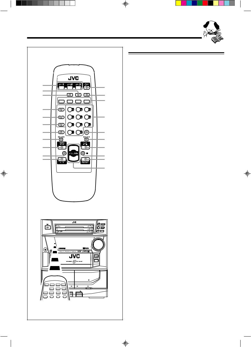
Remote Control
1
2 |
|
SOUND |
S. A. BASS SLEEP |
|||
3 |
|
MODE |
||||
DISPLAY |
|
|
|
|
|
|
|
PTY/EON |
|
– SELECT + |
|||
|
MODE |
|
||||
4 |
TAPE A |
PRO LOGIC |
3 STEREO |
TEST TONE |
||
|
|
|
|
|
|
|
5 |
TAPE B |
– CENTERLEVEL |
+ |
CENTER MODE |
||
|
|
|
|
|
|
|
6 |
REC PAUSE |
– |
LEVELREAR |
+ |
DELAY TIME |
|
|
|
|
|
|
|
|
|
SHIFT |
L |
BALANCE R |
FM MODE |
||
7 |
|
|
|
|
|
|
|
|
|
|
|
|
|
8
9 +
FADE
p |
MUTING |
|
– |
||
q |
||
|
RM–SMXJ75R REMOTE CONTROL
STANDBY
PLAY & EXCHANGE
VOLUME
|
+ |
PHONES |
_ |
PANEL |
|
OPEN / CLOSE |
|
TAPE |
CD |
COMPU |
|
PLAY |
|
CONTROL |
|
AUX |
FM/ AM |
PLAY REC/PLAY
AUTO REVERSE |
AUTO REVERSE |
EJECT |
EJECT |
w
e r
t
y u
i
o
;
a
CD3
CD2
CD1
When using the remote control, point it at the remote sensor on the front panel.
Remote Control
1Disc number buttons (CD1, CD2, and CD3) (16)
Pressing one of these buttons also turns on the unit.
2 S.A.BASS (Signal Adaptive Bass) button (11)
3 SOUND MODE button (11)
4 TAPE A button (19)
5 TAPE B button (19)
6 REC PAUSE button (22)
7 SHIFT button (11, 20)
8 1/ 4(fast left/reverse search) button (17 – 19)
9TAPE 23button (19)
Pressing this button also turns on the unit.
p FADE MUTING button (11)
qAUX button (10)
Pressing this button also turns on the unit.
w  (standby/on) button (10) e SLEEP button (27)
rRDS operation buttons (14)
•DISPLAY MODE, PTY/EON, and SELECT – / + buttons
tNumber buttons (13, 17) Sound control buttons (11, 20)
y FM MODE button (13)
u ¢/ ¡(forward search/fast right) button (17 – 19) i CD £/8button (16)
Pressing this button also turns on the unit. o 7(stop) button (16, 19)
;FM/AM button (13)
Pressing this button also turns on the unit.
a VOLUME + / – button (11, 21)
– 5 –
EN01-09.MXJ850R[B]/f |
5 |
00.4.21, 4:31 PM |
Getting Started
Continued
Unpacking |
|
Connecting Antennas |
|
|
|
After unpacking, check to be sure that you have all the following items.
The number in the parentheses indicates the quantity of the pieces supplied.
•AM loop antenna (1)
•FM antenna (1)
•Remote control (1)
•Batteries (2)
If any is missing, consult your dealer immediately.
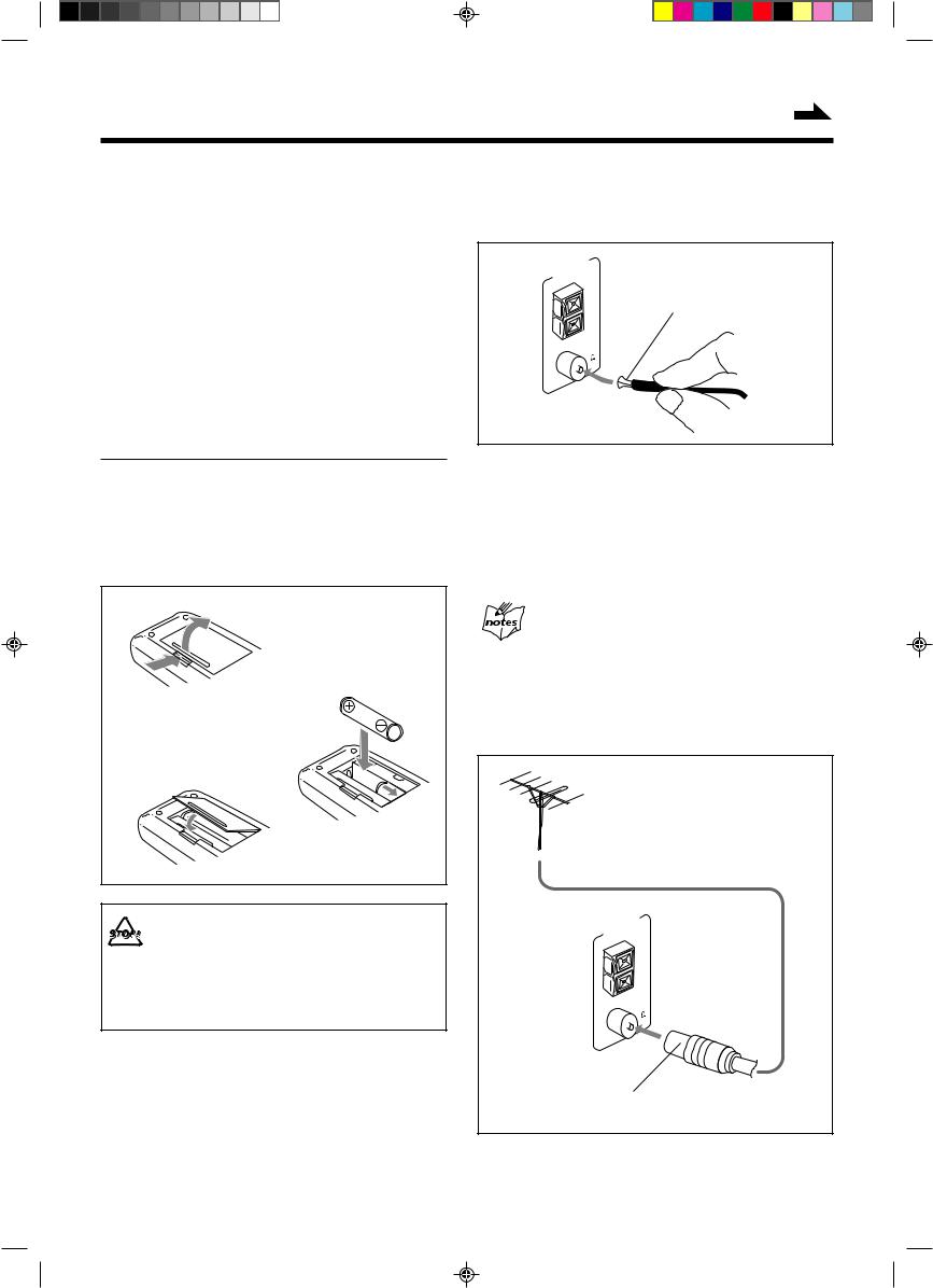
Putting the Batteries into the Remote Control
Insert the batteries — R6P(SUM-3)/AA(15F) — into the remote control, by matching the polarity (+ and –) on the batteries with the + and – markings on the battery compartment.
When the remote control can no longer operate the unit, replace both batteries at the same time.
1 |
|
2 |
R6P(SUM-3)/AA(15F) |
3 |
|
• DO NOT use an old battery together with a new one.
• DO NOT use different types of batteries together.
•DO NOT expose batteries to heat or flame.
•DO NOT leave the batteries in the battery compartment when you are not going to use the remote control for an extended period of time. Otherwise, it will be damaged from battery leakage.
FM antenna
ANTENNA
GND |
||
|
LOOP |
|
AM |
EXT |
|
|
||
FM |
75 |
|
|
|
|
COAXIAL |
||
FM antenna (supplied)
1Attach the FM antenna to the FM 75 Ω
COAXIAL terminal.
2Extend the FM antenna.
3Fasten it up in the position which gives you the best reception.
About the supplied FM antenna
The FM antenna supplied with this unit can be used as temporary measure. If reception is poor, you can connect an outdoor FM antenna.
To connect an outdoor FM antenna
Before connecting it, disconnect the supplied FM antenna.
Outdoor FM antenna (not supplied)
ANTENNA
GND |
||
|
LOOP |
|
AM |
EXT |
|
|
||
FM |
75 |
|
|
|
|
COAXIAL |
||
A 75 Ω antenna with coaxial type connector (DIN 45325) should be used.
– 6 –
EN01-09.MXJ850R[B]/f |
6 |
00.4.21, 4:31 PM |
AM (MW/LW) antenna
1 |
2 |
3 |
ANTENNA
GND |
AM LOOP |
AM EXT |
FM 75 |
COAXIAL |
Vinyl-covered wire (not supplied)
AM loop antenna (supplied)
1Connect the AM loop antenna to the AM LOOP terminals as illustrated.
2Turn the AM loop antenna until you have the best reception.
To connect an outdoor AM antenna
When reception is poor, connect a single vinyl-covered wire to the AM EXT terminal and extend it horizontally. (The AM loop antenna must remain connected.)
For better reception of both FM and AM (MW/LW)
•Make sure the antenna conductors do not touch any other terminals and connecting cords.
•Keep the antennas away from metallic parts of the unit, connecting cords, and the AC power cord.
Connecting Speakers
You can connect a pair of front speakers, one center speaker, a pair of rear speakers, and one subwoofer.
To connect front speakers
1 |
|
2, 3 |
|
|
|
Red |
|
Speaker |
SPEAKERS |
Speaker |
|
RIGHT |
LEFT |
||
|
|
cord |
|
cord |
|
|
|
|
|
|
|
|
Black |
|
|
Right |
|
|
Left |
speaker |
|
|
speaker |
1Press and hold the clamp of the speaker terminal on the rear of the unit.
2Insert the end of the speaker cord into the
terminal.
Match the polarity of the speaker terminals: Red (+) to red (+) and black (–) to black (–).
3 Release the finger from the clamp.
IMPORTANT: Use only speakers with the same speaker impedance as indicated by the speaker terminals on the rear of the unit.
– 7 –
EN01-09.MXJ850R[B]/f |
7 |
00.4.21, 4:31 PM |
Continued
To connect a center speaker and rear speakers |
Connecting Other Equipment |
By connecting a center speaker and rear speakers, you can enjoy Dolby Surround equipped with this unit.
You can connect both analog and digital equipment.
|
Center speaker |
|
RIGHT |
LEFT |
|
REAR |
CENTER |
|
Right rear |
|
Left rear |
speaker |
|
speaker |
• DO NOT connect any equipment while the power 
 is on.
•DO NOT plug in any equipment until all connections are complete.
To connect an analog component
Be sure that the plugs of the audio cords are color coded: White plugs and jacks are for left audio signals, and red ones for right audio signals.
|
AUX |
RIGHT |
LEFT |
|
IN |
|
OUT |
To audio input |
|
Audio/video |
|
equipment |
|
To audio output |
|
•Connect the right rear speaker to the REAR RIGHT jack.
•Connect the left rear speaker to the REAR LEFT jack.
•Connect the center speaker to the CENTER jack.
To connect a subwoofer
By connecting a subwoofer, you can enhance the bass.
SUB WOOFER |
OUT |
To input |
By using audio cords (not supplied), connect:
•Between the audio input jacks on the other equipment and AUX OUT jacks: For recording on the other equipment.
•Between the audio output jacks on the other equipment and AUX IN jacks: For playing the other equipment.
When connecting a VCR
Since this unit is not equipped with the video input and output jacks, connect this unit and the VCR only using the audio cords, then connect the VCR and the TV set directly using the video cord(s).
Connect the input jack of a powered subwoofer to the SUB WOOFER OUT jack, using a monaural audio cord (not supplied).
– 8 –
EN01-09.MXJ850R[B]/f |
8 |
00.4.21, 4:31 PM |
 Loading...