


VS-DT6-8(J)_EN.book Page 1 Monday, January 21, 2002 5:05 PM
COMPACT COMPONENT SYSTEM
VS-DT6/VS-DT8
Consists of CA-VSDT6 and SP-VSDT6
Consists of CA-VSDT8 and SP-VSDT8
1 |
2 |
3 |
4 |
5 |
6 |
7 |
8 |
9 |
10 |
|
+10 |
|
|
|
|
|
|
|
|
|
|
|
|
|
|
|
|
|
|
|
|
|
|
|
|
|
|
|
|
|
|
|
|
|
|
|
|
|
|
|
|
|
|
|
|
|
|
|
|
|
|
|
|
|
|
|
|
|
|
|
|
|
|
|
|
|
|
|
|
|
|
|
|
|
|
|
|
|
|
|
|
|
|
|
|
|
|
|
|
|
|
|
|
|
|
|
|
|
SP-VSDT6 |
||
SP-VSDT6 |
|
|
|
|
CA-VSDT6 |
|
|
|||||||||||||||||
1 |
2 |
3 |
4 |
5 |
6 |
7 |
8 |
9 |
10 |
|
+10 |
|
|
|
|
|
|
|
|
|
|
|
|
|
|
|
|
|
|
|
|
|
|
|
|
|
|
|
|
|
|
|
|
|
|
|
|
|
|
|
|
|
|
|
|
|
|
|
|
|
|
|
|
|
|
|
|
SP-VSDT8 |
|
|
|
|
|
|
|
|
|
|
|
|
|
|
|
|
|
|
|
SP-VSDT8 |
||||
|
|
|
|
|
|
CA-VSDT8 |
|
|
||||||||||||||||||
|
|
|
|
|
|
|
|
|
|
|
|
|
|
|
|
|
|
|
|
|
|
|
|
|
|
|
|
|
|
|
|
|
|
|
|
|
|
|
|
|
|
|
|
|
|
|
|
|
|
|
|
|
|
INSTRUCTIONS
For Customer Use:
Enter below the Model No. and Serial No. which are located either on the rear, bottom or side of the cabinet. Retain this information for future reference.
Model No.
Serial No.
LVT0853-001A [J]
VS-DT6-8(J)_EN.book Page 1 Monday, January 21, 2002 5:05 PM
Warnings, Cautions and Others /
Mises en garde, précautions et indications diverses
(For U.S.A)
CAUTION
RISK OF ELECTRIC
SHOCK
DO NOT OPEN
CAUTION: TO REDUCE THE RISK OF ELECTRIC SHOCK
DO NOT REMOVE COVER (OR BACK)
NO USER SERVICEABLE PARTS INSIDE
REFER SERVICING TO QUALIFIED SERVICE PERSONNEL.
The lightning flash with arrowhead symbol, within an equilateral triangle is intended to alert the user to the presence of uninsulated “dangerous voltage” within the product’s enclosure that may be of sufficient magnitude to constitute a risk of electric shock to persons.
The exclamation point within an equilateral triangle is intended to alert the user to the presence of important operating and maintenance (servicing) instructions in the literature accompanying the appliance.
WARNING: TO REDUCE THE RISK OF FIRE OR
ELECTRIC SHOCK, DO NOT EXPOSE THIS APPLI-
ANCE TO RAIN OR MOISTURE.
INFORMATION
This equipment has been tested and found to comply with the limits for a Class B digital device, pursuant to Part 15 of the FCC Rules. These limits are designed to provide reasonable protection against harmful interference in a residential installation. This equipment generates, uses, and can radiate radio frequency energy and, if not installed and used in accordance with the instructions, may cause harmful interference to radio communications. However, there is no guarantee that interference will not occur in a particular installation. If this equipment does cause harmful interference to radio or television reception, which can be determined by turning the equipment off and on, the user is encouraged to try to correct the interference by one or more of the following measures:
–Reorient or relocate the receiving antenna.
–Increase the separation between the equipment and receiver.
–Connect the equipment into an outlet on a circuit different from that to which the receiver is connected.
–Consult the dealer or an experienced radio/ TV technician for help.
G-1
VS-DT6-8(J)_EN.book Page 2 Monday, January 21, 2002 5:05 PM
For Canada/pour le Canada
CAUTION: TO PREVENT ELECTRIC SHOCK, MATCH WIDE BLADE OF PLUG TO WIDE SLOT, FULLY INSERT.
PRECAUTION: POUR EVITER LES CHOCS ELECTRIQUES, INTRODUIRE LA LAME LA PLUS LARGE DE LA FICHE DANS LA BORNE CORRESPONDANTE DE LA PRISE ET POUSSER JUSQUAU FOND
For Canada/pour Le Canada
THIS DIGITAL APPARATUS DOES NOT EXCEED THE CLASS B LIMITS FOR RADIO NOISE EMISSIONS FROM DIGITAL APPARATUS AS SET OUT IN THE INTERFER- ENCE-CAUSING EQUIPMENT STANDARD ENTITLED “DIGITAL APPARATUS,” ICES-003 OF THE DEPARTMENT OF COMMUNICATIONS.
CET APPAREIL NUMERIQUE RESPECTE LES LIMITES DE BRUITS RADIOELECTRIQUES APPLICABLES AUX APPAREILS NUMERIQUES DE CLASSE B PRESCRITES DANS LA NORME SUR LE MATERIEL BROUILLEUR: “APPAREILS NUMERIQUES”, NMB-003 EDICTEE PAR LE MINISTRE DES COMMUNICATIONS.
1.CLASS 1 LASER PRODUCT
2.DANGER: Invisible laser radiation when open and interlock failed or defeated. Avoid direct exposure to beam.
3.CAUTION: Do not open the top cover. There are no user serviceable parts inside the unit; leave all servicing to qualitied service personnel.
1.PRODUIT LASER CLASSE 1
2.ATTENTION: Radiation laser invisible quand l’appareil est ouvert ou que le verrouillage est en panne ou désactivé. Eviter une exposition directe au rayon.
3.ATTENTION: Ne pas ouvrir le couvercle du dessus. Iln’y a aucune pièce utilisable à l’intérier. Laisser à un personnel qualifié le soin de réparer votre appareil.
CAUTION
To reduce the risk of electrical shocks, fire, etc.: 1 Do not remove screws, covers or cabinet.
2. Do not expose this appliance to rain or moisture.
Caution —  switch!
Disconnect the mains plug to shut the power off completely. The  switch in any position does not disconnect the mains line. The power can be remote controlled.
ATTENTION
Afin d’èviter tout risque d’électrocution, d’lncendie. etc.:
1.Ne pas enlever les vis ni les panneaux et ne pas ouvrir le coffret de l’appareil.
2.Ne pas exposer l’appareil à la pluie ni à l’humidité.
Attention — Commutateur 
Déconnecter la fiche de secteur poru couper complètement le courant. Le commutateur  ne coupe jamais complètement la ligne de secteur, quelle que soit sa position. Le courant peut être télécommandé.
CAUTION
■About the Internal Cooling Fan
This unit includes an internal cooling fan, so as to allow for highpower operation within a small space.
This fan comes on when the sound level is set high, and may also come on even at low sound levels if the internal temperature rises. To ensure effective fan operation, please leave at least 1cm (7/16”) clearance on each side of the unit.
ATTENTION
■A propos du ventilateur de refroidissement interne
Cet appareil est équipé d’un ventilateur de refroidissement interne afin de permettre un fonctionnement à haute puissance dans un espace limité.
Ce ventilateur se met en marche quand le niveau sonore est élevé et peut aussi se déclencher même à un niveau bas si la température interne augmente. Pour garantir un fonctionnement effectif du ventilateur, veuillez laisser un espace libre de 1 cm au moins de chaque côté de l’appareil.
G-2
VS-DT6-8(J)_EN.book Page 1 Monday, January 21, 2002 5:05 PM
Introduction
Thank you for purchasing the JVC Compact Component System.
We hope it will be a valued addition to your home, giving you years of enjoyment.
Be sure to read this instruction manual carefully before operating your new stereo system.
In it you will find all the information you need to set up and use the system.
If you have a query that is not answered by the manual, please contact your dealer.
Features
Here are some of the things that make your System both powerful and simple to use.
■With the slot-loading CD mechanism, you can choose to place the System either vertically or horizontally.
■The controls and operations have been redesigned to make them very easy to use, freeing you to just enjoy the music.
• With JVC’s COMPU PLAY you can turn on the System and automatically start the Radio or CD Player with a single touch.
■The System incorporates Active Hyper Bass PRO circuitry to faithfully reproduce low frequency sounds.
■A 45-station preset capability (30 FM and 15 AM) in addition to auto-seek and manual tuning.
■CD options that include repeat, random and program play.
■Timer functions; Daily Timer and Sleep Timer.
■You can connect various external units, such as an MD recorder.
■The system can play CD-R and CD-RW after they have been finalized.
■You can play back your original CD-R or CD-RW recorded in Music CD format. (However they may not be played back depending on their characteristics or recording conditions.)
How This Manual Is Organized
•Basic information that is the same for many different functions - e.g. setting the volume - is given in the section ‘Basic Operations’, and not repeated under each function.
•The names of buttons/controls and display messages are written in all capital letters: e.g. FM/AM, “CD NO DISC”.
•System functions are written with an initial capital letter only: e.g. Normal Play.
Use the table of contents to look up specific information you require.
We have enjoyed making this manual for you, and hope it serves you in enjoying the many features built into your System.
WARNINGS
•DO NOT PUT ANYTHING ON THE PANEL. IF THE SYSTEM IS OPERATED WITH SOMETHING PUT ON THE PANEL, IT WILL BE DAMAGED WHEN YOU TRY TO OPEN THE PANEL.
•SUPPLIED SPEAKERS ARE EXCLUSIVELY FOR THIS SYSTEM. USING WITH OTHER DEVICES WILL DAMAGE THE SPEAKERS.
IMPORTANT CAUTIONS
1Installation of the System
•Select a place which is level, dry and neither too hot nor too cold. (Between 5°C and 35°C or 41°F and 95°F.)
•Leave sufficient distance between the System and a TV.
•Do not use the System in a place subject to vibrations.
2Power cord
•Do not handle the power cord with wet hands!
•Some power is always consumed as long as the power cord is connected to the wall outlet.
•When unplugging the System from the wall outlet, always pull the plug, not the power cord.
3Malfunctions, etc.
•There are no user serviceable parts inside. In case of system failure, unplug the power cord and consult your dealer.
•Do not insert any metallic object into the System.
•Do not insert your hand between the Panel and the main body when the Panel is being closed.
1
VS-DT6-8(J)_EN.book Page 2 Monday, January 21, 2002 5:05 PM |
|
Table of Contents |
|
Introduction ........................................................................................................ |
1 |
Features ...................................................................................................................................... |
1 |
How This Manual Is Organized ................................................................................................. |
1 |
WARNINGS .............................................................................................................................. |
1 |
IMPORTANT CAUTIONS ....................................................................................................... |
1 |
Getting Started ................................................................................................... |
3 |
Accessories................................................................................................................................. |
3 |
How To Put Batteries In the Remote Control ............................................................................ |
3 |
Connecting the FM Antenna ...................................................................................................... |
4 |
Connecting the AM Antenna...................................................................................................... |
5 |
Connecting the Speakers ............................................................................................................ |
6 |
Connecting a Subwoofer ............................................................................................................ |
7 |
Connecting External Equipment ................................................................................................ |
7 |
Connecting an MD Recorder, etc (Digital Output) .................................................................... |
8 |
Connecting the AC Power Cord................................................................................................. |
8 |
Installing the Unit on the Stand.................................................................................................. |
8 |
Installing the Equipment on the Wall......................................................................................... |
9 |
Changing the Display and Control Buttons Settings................................................................ |
10 |
Using the Remote Control........................................................................................................ |
11 |
COMPU Play............................................................................................................................ |
11 |
Basic Operations ............................................................................................. |
12 |
Turning the Power On and Off................................................................................................. |
12 |
Adjusting the Brightness (DIMMER) ...................................................................................... |
12 |
Changing the Color (COLOR) (VS-DT8 only)........................................................................ |
13 |
Adjusting the Volume .............................................................................................................. |
13 |
Reinforcing the Bass Sound (AHB PRO) ................................................................................ |
14 |
Tone Control (BASS/TREBLE)............................................................................................... |
14 |
Showing the Time (DISPLAY)................................................................................................ |
14 |
Using the Tuner................................................................................................ |
15 |
Tuning In a Station................................................................................................................... |
15 |
Presetting Stations .................................................................................................................... |
16 |
To Change the FM Reception Mode ........................................................................................ |
16 |
Using the CD Player......................................................................................... |
17 |
To Insert a CD .......................................................................................................................... |
17 |
To Unload a CD ....................................................................................................................... |
18 |
Basics of Using the CD Player — Normal Play....................................................................... |
18 |
Programming the Playing Order of the Tracks ........................................................................ |
19 |
Random Play ............................................................................................................................ |
20 |
Repeating Tracks...................................................................................................................... |
20 |
Child Lock................................................................................................................................ |
20 |
Using External Equipment .............................................................................. |
21 |
Listening to External Equipment.............................................................................................. |
21 |
Recording the System’s Source to External Equipment .......................................................... |
21 |
Using the Timers.............................................................................................. |
22 |
Setting the Clock ...................................................................................................................... |
22 |
Setting the Daily Timer ............................................................................................................ |
23 |
Setting the SLEEP Timer ......................................................................................................... |
24 |
Care And Maintenance .................................................................................... |
25 |
Troubleshooting............................................................................................... |
26 |
Specifications.................................................................................... |
Back cover |
2
VS-DT6-8(J)_EN.book Page 3 Monday, January 21, 2002 5:05 PM
Getting Started
Accessories
Make sure that you have all of the following items, which are supplied with the System.
Power Cord (1)
AM Loop Antenna (1)
Remote Control (1)
Batteries (2)
FM Wire Antenna (1)
Speaker Cords (2)
Stand (1) (for Center Unit)
Legs (2) (for Stand)
Screw (1) (for Stand)
Paper Pattern (1)
If any of these items are missing, contact your dealer immediately.
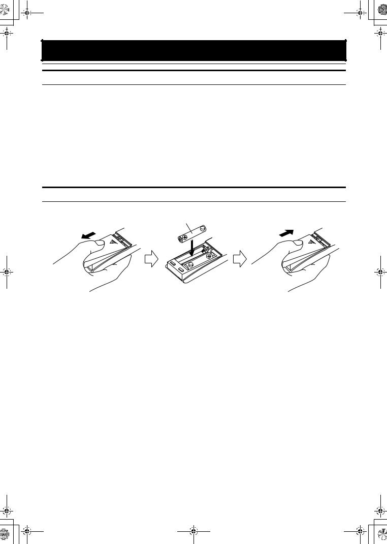
How To Put Batteries In the Remote Control
Match the polarity (+ and –) on the batteries with the + and – markings in the battery compartment.
R6P(SUM-3)/AA(15F)
 CAUTION:
• Handle batteries properly.
■To avoid battery leakage or explosion:
•Remove batteries when the Remote Control will not be used for a long time.
•When you need to replace the batteries, replace both batteries at the same time with new ones.
•Do not use an old battery with a new one.
•Do not use different types of batteries together.
3
VS-DT6-8(J)_EN_1.fm Page 4 Monday, January 21, 2002 6:00 PM
Getting Started
 CAUTION:
• Make all connections before plugging the System into an AC power outlet.
(Only if you install the Center Unit vertically)
• To place the Center Unit vertically, the Stand and Legs must be attached. (See page 8.) To make connections, let the cords pass in the holes of the Stand as shown in the diagram before attaching the Stand and Legs.
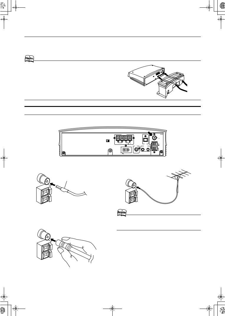
Connecting the FM Antenna
Rear Panel of the Center Unit
|
|
SPEAKERS |
|
|
ANTENNA |
|
|
|
|
|
|
FM |
|
|
|
|
|
|
(75 |
) |
H |
|
|
|
|
COAXIAL |
|
V |
L |
|
|
|
|
|
|
R |
|
|
AM |
|
|
|
DISP.SET |
|
|
CD DIGITAL |
LOOP |
|
|
SPEAKER IMPEDANCE 4 |
16 |
OUT |
|
|
|
SUB |
|
MD/AUX |
WOOFER |
OUT |
IN |
|
|
AM |
AC IN |
|
EXT |
|
|
Using the Supplied Wire Antenna If reception is poor, connect the outdoor antenna.
FM wire antenna (supplied)
FM outdoor antenna
(Not supplied) Coaxial cable
Using the Coaxial Type Connector (Not Supplied)
A 75 Ω antenna with coaxial type connector should be connected to the FM 75 Ω COAXIAL terminal.
•Before attaching a 75 Ω coaxial lead (the kind with a round wire going to an outdoor antenna), disconnect the supplied FM Wire Antenna.
4
VS-DT6-8(J)_EN.book Page 5 Monday, January 21, 2002 5:05 PM
Getting Started
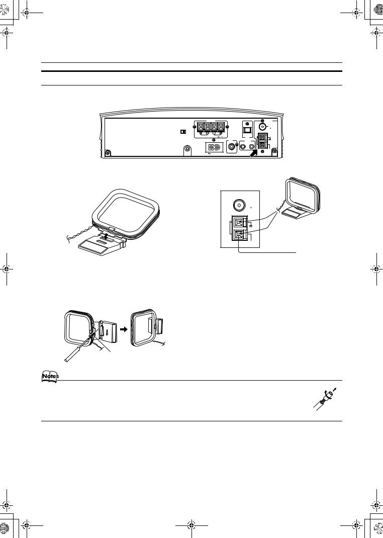
Connecting the AM Antenna
Rear Panel of the Center Unit
|
|
SPEAKERS |
|
|
ANTENNA |
|
|
|
|
|
|
FM |
|
|
|
|
|
|
(75 |
) |
H |
|
|
|
|
COAXIAL |
|
V |
L |
|
|
|
|
|
|
R |
|
|
AM |
|
|
|
DISP.SET |
|
|
CD DIGITAL |
LOOP |
|
|
SPEAKER IMPEDANCE 4 |
16 |
OUT |
|
|
|
|
|
|
SUB |
MD/AUX |
|
|
|
|
|
WOOFER |
OUT |
IN |
|
|
|
|
|
|
AM |
|
|
|
AC IN |
|
|
EXT |
|
|
|
|
|
|
|
|
AM loop antenna (Supplied)
Attach the AM loop to its base by snapping the tabs on the loop into the slot in the base.
ANTENNA |
FM |
(75 ) |
COAXIAL |
AM |
LOOP |
AM |
EXT |
Outdoor single vinylcovered wire
(not supplied)
Turn the loop until you have the best reception.
• The AM loop antenna can be attached to a wall.
Screw (not supplied)
•If the AM loop antenna wire is covered with vinyl, remove the vinyl by twisting it as shown in the diagram.
•Make sure the antenna conductors do not touch any other terminals, connecting cords and power cord. This could cause poor reception.
•If reception is poor, connect an outdoor single vinyl-covered wire to the AM EXT terminal. (Keep the AM loop antenna connected.)
5
VS-DT6-8(J)_EN.book Page 6 Monday, January 21, 2002 5:05 PM
Getting Started
 CAUTION:
•Make all connections before plugging the System into an AC power outlet.
•Handling the speakers
As this is a precision instrument, handle it carefully so as to protect it from shocks.
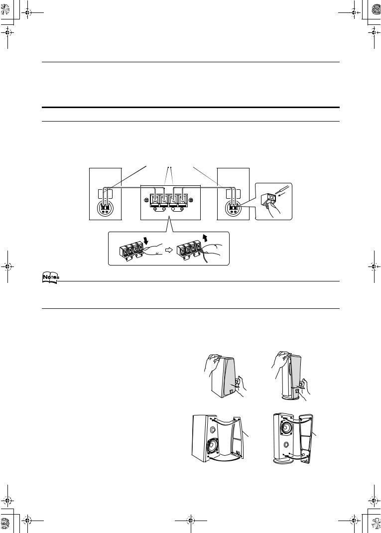
Connecting the Speakers
These speakers are exclusively for this system. Using with other devices will damege the speakers.
1.Open each of the terminals to connect the speaker wire leads.
2.Connect the speaker cords between the Speaker terminals of the Unit and the terminals of the Speakers. Connect the cords with a black line to the (–) terminals and cords without a black line to the (+) terminals.
3.Close each of the terminals to securely connect the cords.
Right side (rear view) |
Marked with a black line |
Left side (rear view) |
|
SPEAKERS |
R |
L |
SPEAKER IMPEDANCE 4  16
16 
•Since both speakers are the same, you can put either one to the right or left side.
•Do not connect other speakers to the Unit. The difference of the load impedance causes failures.
•Do not use the supplied speakers in parallel with other speakers.
 CAUTION:
•Although the speaker SP-VSDT8 has internal magnetic shielding, a TV may display irregular colors if located near the speakers. If this happens, set the speakers away from the TV.
Removing the speaker grilles
The speaker grilles can be removed.
When removing:
1.Pull the bottom towards you with your fingers.
2.Also pull the top towords you.
When attaching the speaker grilles:
Attach the speaker grilles as shown in the diagram.
(SP-VSDT6) |
(SP-VSDT8) |
(SP-VSDT6) |
(SP-VSDT8) |
Speaker |
Speaker |
grille |
grille |
6
VS-DT6-8(J)_EN.book Page 7 Monday, January 21, 2002 5:05 PM
Getting Started
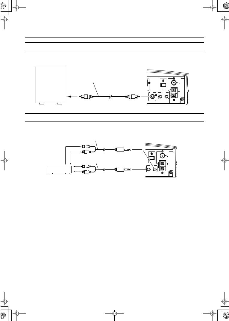
Connecting a Subwoofer
Connect a signal cord (not supplied) between the System’s SUBWOOFER terminal and the input terminal of an external subwoofer.
Subwoofer (not supplied)
Signal cord (not supplied) |
|
ANTENNA |
|
|
|
|
|
|
|
FM |
|
|
|
(75 |
) |
|
|
COAXIAL |
|
|
|
AM |
|
|
CD DIGITAL |
LOOP |
|
|
OUT |
|
|
SUB |
MD/AUX |
|
|
WOOFER |
OUT |
IN |
|
|
|
AM |
|
|
|
EXT |
|
Connecting External Equipment
Connect signal cords (not supplied) between the System’s MD/AUX-OUT/IN terminals and the output/input terminals of the external MD recorder, tape deck, etc.
You can then listen to the external source through the System or record the System’s CD player or tuner to the external unit.
Signal cord (not supplied)
MD recorder or tape deck (not supplied)
|
Stereo mini-plug |
ANTENNA |
|
Pin-plug x 2 |
FM |
|
|
|
) |
||
|
|
(75 |
|
Signal cord (not supplied) |
|
COAXIAL |
|
CD DIGITAL |
LOOP |
|
|
|
|
AM |
|
|
OUT |
|
|
|
MD/AUX |
|
|
|
OUT |
IN |
|
|
Stereo mini-plug |
AM |
|
|
EXT |
|
|
Pin-plug x 2 |
|
|
|
7
 Loading...