


SP-UXV100
Table of contents
 Loading...
INSTRUCTIONS
For Customer Use:
Enter below the Model No. and Serial No.
which are located either on the rear, bot-
tom or side of the cabinet. Retain this
information for future reference.
Model No.
Serial No.
GVT0056-008A
[B]
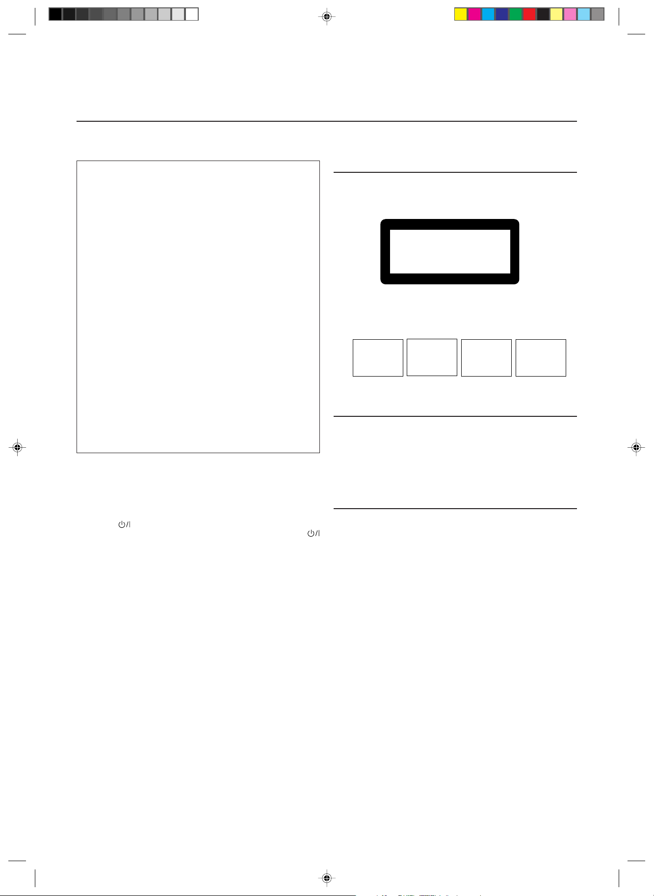
MICRO COMPONENT SYSTEM
UX-V100— Consists of CA-UXV100 and SP-UXV100.
AUTO REVERSE
AUTO TAPE SELECTOR
DOWN UPMULTI CONTROL
TAPE FM/AM CD
STANDBY
PHONES
AUX
REC
REV.
MODE
AHB
PRO
TIMER
CLOCK
VERTICAL DISC
LOADING MECHANISM
COMPACT
DIGITAL AUDIO
VOLUME
CD
OPEN/CLOSE
REMOTE CONTROL RM-SUXV10E
CANCELTREBLE
FM/AM
FM
MODE
DISPLAYSLEEP
AUX
TAPE CD
CD
BASS
AHB
PRO
DOWN
RANDOM
UP
AUTO
PRESET
REPEAT
SET
PROGRAM
VOLUME
TAPE
MICRO COMPONENT SYSTEM
UX-V100
COVER.UX-V100[B]f 12/12/00, 12:35 PM3
G-1
Warnings, Cautions and Others
IMPORTANT for the U.K.
DO NOT cut off the mains plug from this equipment. If the plug
fitted is not suitable for the power points in your home or the
cable is too short to reach a power point, then obtain an appro-
priate safety approved extension lead or consult your dealer.
BE SURE to replace the fuse only with an identical approved
type, as originally fitted.
If nonetheless the mains plug is cut off ensure to remove the fuse
and dispose of the plug immediately, to avoid a possible shock
hazard by inadvertent connection to the mains supply.
If this product is not supplied fitted with a mains plug then follow
the instructions given below:
IMPORTANT:
DO NOT make any connection to the terminal which is marked
with the letter E or by the safety earth symbol or coloured green
or green-and-yellow.
The wires in the mains lead on this product are coloured in
accordance with the following code:
Blue : Neutral
Brown : Live
As these colours may not correspond with the coloured markings
identifying the terminals in your plug proceed as follows:
The wire which is coloured blue must be connected to the
terminal which is marked with the letter N or coloured black.
The wire which is coloured brown must be connected to the
terminal which is marked with the letter L or coloured red.
IF IN DOUBT - CONSULT A COMPETENT ELECTRICIAN.
IMPORTANT FOR LASER PRODUCTS
REPRODUCTION OF LABELS
1 CLASSIFICATION LABEL, PLACED ON REAR ENCLOSURE
CLASS 1
LASER PRODUCT
2 WARNING LABEL, PLACED INSIDE THE UNIT
DANGER: Invisible laser
radiation when open and
interlock failed or defeated.
AVOID DIRECT EXPOSURE
TO BEAM.
(e)
VARNING: Osynlig laser-
strålning när denna del är
öppnad och spärren är
urkopplad. Betrakta ej
strålen.
(s)
ADVARSEL: Usynlig laser-
stråling ved åbning, når
sikkerhedsafbrydere er ude
af funktion. Undgå udsæt-
telse for stråling
(d)
VARO: Avattaessa ja suo-
jalukitus ohitettaessa olet
alttiina näkymättömälle
lasersäteilylle. Älä katso
säteeseen.
(f)
1. CLASS 1 LASER PRODUCT
2. DANGER: Invisible laser radiation when open and interlock failed
or defeated. Avoid direct exposure to beam.
3. CAUTION: Do not open the top cover. There are no user
serviceable parts inside the Unit; leave all servicing to qualified
service personnel.
CAUTION
To reduce the risk of electrical shocks, fire, etc.:
1. Do not remove screws, covers or cabinet.
2. Do not expose this appliance to rain or moisture.
Caution –– switch!
Disconnect the mains plug to shut the power off completely. The
switch in any position does not disconnect the mains line. The power can
be remote controlled.
G1-G3.UX-V100[B]f 12/12/00, 12:33 PM2
G-2
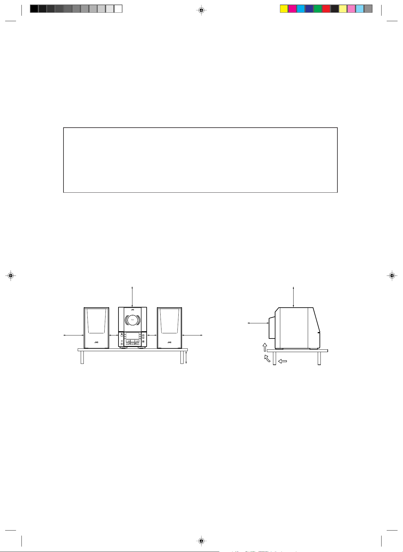
Front view Side view
Caution: Proper Ventilation
To avoid risk of electric shock and fire, and to prevent damage, locate the apparatus as follows:
1 Front:
No obstructions and open spacing.
2 Sides/ Top/ Back:
No obstructions should be placed in the areas shown by the dimensions below.
3 Bottom:
Place on the level surface. Maintain an adequate air path for ventilation by placing on a stand with a height of 10 cm
or more.
UX-V100
10 cm
15 cm
15 cm
15 cm
1 cm 1 cm
TAPE FM/AM CD
VERTICAL DISC
LOADING MECHANISM
COMPACT
DIGITAL AUDIO
MICRO COMPONENT SYSTEM
UX-V100
15 cm
UX-V100
15 cm
G1-G3.UX-V100[B]f 12/12/00, 12:33 PM3

G-3
SAFETY INSTRUCTIONS
“SOME DOS AND DON’TS ON THE SAFE USE OF EQUIPMENT”
This equipment has been designed and manufactured to meet international safety standards but, like any electrical equipment, care
must be taken if you are to obtain the best results and safety is to be assured.
✮✮✮✮✮✮✮✮✮✮✮✮✮✮✮✮✮✮✮✮✮✮✮✮✮✮✮✮✮✮✮✮✮✮✮✮✮✮✮✮✮✮✮✮✮✮✮
Do read the operating instructions before you attempt to use the equipment.
Do ensure that all electrical connections (including the mains plug, extension leads and interconnections between pieces of
equipment) are properly made and in accordance with the manufacturer’s instructions. Switch off and withdraw the mains plug when
making or changing connections.
Do consult your dealer if you are ever in doubt about the installation, operation or safety of your equipment.
Do be careful with glass panels or doors on equipment.
✮✮✮✮✮✮✮✮✮✮✮✮✮✮✮✮✮✮✮✮✮✮✮✮✮✮✮✮✮✮✮✮✮✮✮✮✮✮✮✮✮✮✮✮✮✮✮
DON’T continue to operate the equipment if you are in any doubt about it working normally, or if it is damaged in any way–switch
off, withdraw the mains plug and consult your dealer.
DON’T remove any fixed cover as this may expose dangerous voltages.
DON’T leave equipment switched on when it is unattended unless it is specifically stated that it is designed for unattended operation
or has a standby mode.
Switch off using the switch on the equipment and make sure that your family know how to do this.
Special arrangements may need to be made for infirm or handicapped people.
DON’T use equipment such as personal stereos or radios so that you are distracted from the requirements of traffic safety. It is illegal
to watch television whilst driving.
DON’T listen to headphones at high volume as such use can permanently damage your hearing.
DON’T obstruct the ventilation of the equipment, for example with curtains or soft furnishings.
Overheating will cause damage and shorten the life of the equipment.
DON’T use makeshift stands and NEVER fix legs with wood screws — to ensure complete safety always fit the manufacturer’s
approved stand or legs with the fixings provided according to the instructions.
DON’T allow electrical equipment to be exposed to rain or moisture.
ABOVE ALL
— NEVER let anyone, especially children, push anything into holes, slots or any other opening in the case — this could result
in a fatal electrical shock.;
— NEVER guess or take chances with electrical equipment of any kind — it is better to be safe than sorry!
G1-G3.UX-V100[B]f 12/12/00, 12:33 PM4
1
Thank you for purchasing the JVC Micro Component System.
We hope it will be a valued addition to your home, giving you years of enjoyment.
Be sure to read this instruction manual carefully before operating your new stereo system.
In it you will find all the information you need to set up and use the system.
If you have any query that is not answered by the manual, please contact your dealer.
Features
Here are some of the things that make your System both powerful and simple to use.
■ The controls and operations have been designed to make them very easy to use, freeing you to just enjoy the music.
• With JVC’s COMPU PLAY you can turn on the System and automatically start the Radio, Cassette deck or CD
Player with a single touch.
■ The System incorporates Active Hyper Bass PRO circuitry to faithfully reproduce low frequency sounds.
■ Forty-five-station preset capability (30 FM and 15 AM (MW/LW)) in addition to auto-seek and manual tuning.
■ Versatile CD options include repeat, random and program play.
■ Timer functions; Daily Timer, Recording Timer and Sleep Timer.
■ Auto-reverse tape function.
■ You can connect an audio equipment — used only as a playback device.
How This Manual Is Organized
• Basic information that is the same for many different functions – e.g. setting the volume – is given in the section “Common
Operations”, and not repeated under each function.
• The names of buttons/controls and display messages are written in all capital letters: e.g. TAPE, “NO DISC”.
IMPORTANT PRECAUTIONS
1 Installation of the System
• Select a place which is level, dry and neither too hot nor too cold. (Between 5°C and 35°C.)
• Leave sufficient distance between the System and a TV.
• Do not use the System in a place subject to vibrations.
2 Power cord
• Do not handle the power cord with wet hands!
• Some power is always consumed as long as the power cord is connected to the wall outlet.
• When unplugging the System from the wall outlet, always pull the plug, not the power cord.
3 Malfunctions, etc.
• There are no user serviceable parts inside. In case of a system failure, unplug the power cord and consult your dealer.
• Do not insert any metallic object into the System.
Table of Contents
Features.................................................................................. 1
How This Manual Is Organized.............................................1
IMPORTANT PRECA UTIONS............................................1
Getting Started ...........................................................2
Common Operations..................................................6
Using the Tuner ..........................................................8
Using the CD Player .................................................10
Using the Cassette Deck (Listening to a Tape) ..... 13
Using the Cassette Deck (Recording) ................... 14
Using External Equipment.......................................16
Using the Timers ......................................................17
Care and Maintenance .............................................20
Troubleshooting ....................................................... 21
Specifications ...........................................................22
EN01-09.UX-V100[B]f 12/12/00, 12:34 PM1
2
Getting Started
Accessories
Make sure that you have all of the following items, which are supplied with the System.
AC Power Cord (1)
AM Loop Antenna (1)
Remote Control (1)
Batteries (2)
FM Wire Antenna (1)
If any of these items are missing, contact your dealer immediately.
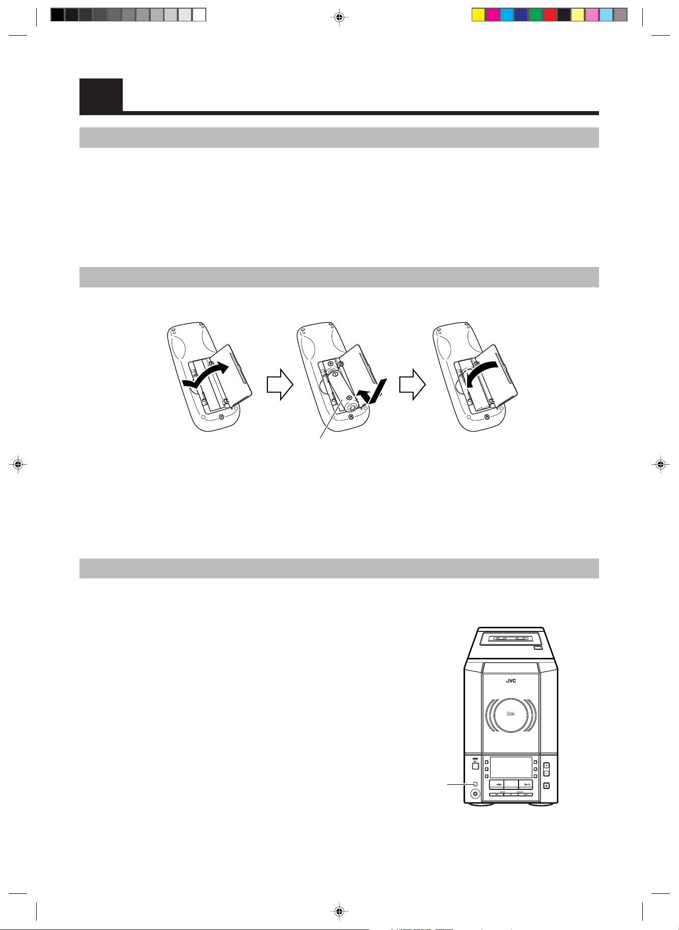
How to Put Batteries in the Remote Control
Match the polarity (+ and –) on the batteries with the + and – markings in the battery compartment.
CAUTION: Handle batteries properly.
To avoid battery leakage or explosion:
• Remove batteries when the Remote Control will not be used for a long time.
• When you need to replace the batteries, replace both batteries at the same time with new ones.
• Do not use an old battery with a new one.
• Do not use different types of batteries together.
Using the Remote Control
The Remote Control makes it easy to use many of the functions of the System from a distance of up to 7 m away.
You need to point the Remote Control at the remote sensor on the System’s front panel.
Remote sensor
R6(SUM-3)/AA(15F)
AUTO REVERSE
AUTO TAPE SELECTOR
TAPE
DOWN UPMULTI CONTROL
TAPE FM/AM CD
STANDBY
PHONES
AUX
REC
REV.
MODE
AHB
PRO
TIMER
CLOCK
VERTICAL DISC
LOADING MECHANISM
COMPACT
DIGITAL AUDIO
VOLUME
CD
OPEN/CLOSE
MICRO COMPONENT SYSTEM
UX-V100
EN01-09.UX-V100[B]f 12/12/00, 12:34 PM2
3
CAUTION: Make all connections before plugging the System into an AC power outlet.
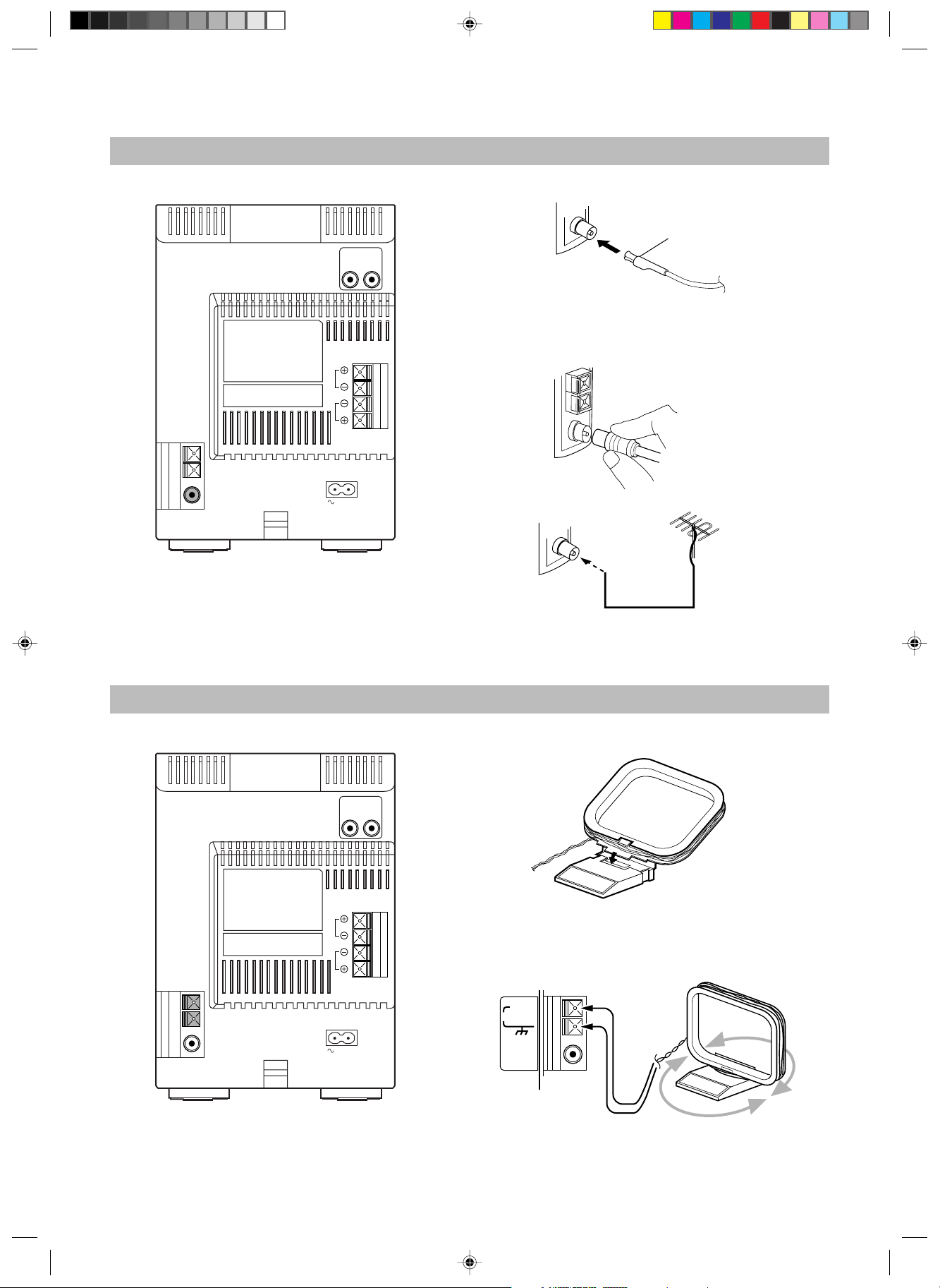
Connecting the FM Antenna
AM EXT
AM LOOP
FM (75Ω)
COAXIAL
ANTENNA
Turn the loop until you have the best reception.
CAUTION:
To avoid noise, keep antennas away from the
System, the connecting cord and the AC power
cord.
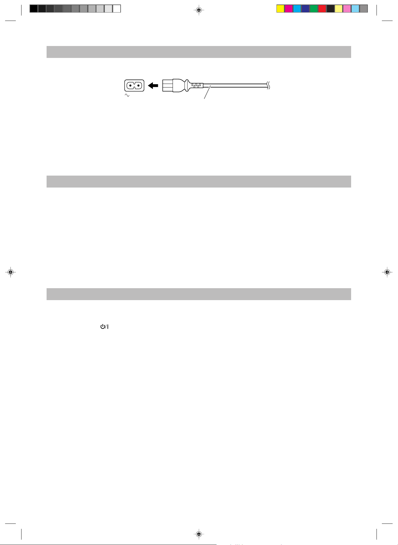
Connecting the AM (MW/LW) Antenna
RL
R
L
SPEAKERS
IMPEDANCE
MIN 4Ω
AC IN
AM Loop Antenna (supplied)
Attach the AM loop to its base by snapping the tabs on the loop
into the slot in the base.
Using the supplied Wire Antenna
Using the coaxial type connector
(not supplied)
A 75 Ω antenna with coaxial type connector (IEC or DIN 45325)
should be connected to the FM (75 Ω) COAXIAL terminal.
If reception is poor, connect the outdoor antenna.
Note: Before attaching a 75 Ω coaxial lead (the kind with a
round wire going to an outdoor antenna), disconnect the
supplied FM Wire Antenna.
FM Wire Antenna
(supplied)
RL
R
L
SPEAKERS
IMPEDANCE
MIN 4Ω
AC IN
Coaxial cable
FM outdoor antenna
(not supplied)
Rear Panel of the Unit
Rear Panel of the Unit
EN01-09.UX-V100[B]f 12/12/00, 12:34 PM3

4
CAUTION: Make all connections before plugging the System into an AC power outlet.
Connecting the Speakers
For each speaker, connect one end of the speaker wire to the speaker terminals on the back of the System.
1. Open each of the terminals and insert the speaker wires firmly, then close the terminals.
2. Connect the red (+) and black (–) wires of the right side speaker to the red (+) and black (–) terminals marked R on the System.
Connect the red (+) and black (–) wires of the left side speaker to the red (+) and black (–) terminals marked L on the System.
CAUTION:
If a TV is installed near the speakers, the picture on the TV may be distorted. If this happens, set the
speakers away from the TV.
Connecting External Equipment
You can connect an audio equipment — used only as a playback device.
Connect the audio output terminals on the other equipment and the LINE IN (AUX) terminals on the rear, using an audio cord (not supplied).
L
R
SPEAKERS
IMPEDANCE
MIN 4Ω
Right speaker (rear side)
Left speaker (rear side)
Black
LINE IN
(AUX)
RL
To audio output
Signal cord (not supplied)
Pin-plug x 2
Pin-plug x 2
MD recorder or cassette
deck (not supplied)
EN01-09.UX-V100[B]f 12/12/00, 12:34 PM4
5
Connecting the AC Power Cord
Firmly insert the supplied AC power cord into the AC inlet on the back of the Unit.
CAUTIONS:
• ONLY USE JVC POWER CORD PROVIDED WITH THIS SYSTEM TO AVOID MALFUNCTION OR DAMAGE
TO THE SYSTEM.
• BE SURE TO UNPLUG THE POWER CORD FROM THE OUTLET WHEN YOU ARE GOING OUT OR WHEN
THE SYSTEM IS NOT IN USE FOR AN EXTENDED PERIOD OF TIME.
Now you can plug the AC power cord into the wall outlet, and your System is at your command!
COMPU PLAY
The JVC’s COMPU PLAY feature lets you control the most frequently used System functions with a single touch.
With One Touch Operation you can play a CD, a tape, turn on the radio, or listen to an external equipment at a single press of the play button
for that function. One Touch Operation turns the power on for you, then starts the function you have specified.
How One Touch Operation works in each case is explained in the section dealing with that function.
The COMPU PLAY buttons are:
AUTOMATIC POWER ON
The System automatically turns on with the following operation.
• When you press the CD OPEN/CLOSE 0 button on the Unit (or CD 0 button on the Remote Control), the System automatically turns
on and the CD cover opens to allow CD insertion. However, this operation does not change the source to CD.
When you press the
button to turn on or off the System, the CD cover will automatically close if it is open.
On the Unit
CD #/8 button
FM/AM button
TAPE @ # button
AUX button
On the Remote Control
CD #/8 button
FM/AM button
TAPE @ # button
AUX button
AC IN
AC power cord
EN01-09.UX-V100[B]f 12/12/00, 12:34 PM5
Loading...