


SERVICE MANUAL
Model 330
Model 340 SC
Model 370 SC
Hughes-JVC Technology Corporation
2310 Camino Vida Roble, Carlsbad, CA 92009-1504
760-929-5300 FAX 760-929-5410 e- service@hjt.com
DECLARATION OF CONFORMITY
PER ISO/IEC GUIDE 22 AND EN 45014

Manufacturer: Hughes-JVC Technology Corporation
2310 Camino Vida Roble
Carlsbad, CA 92009-1504
USA
Hughes-JVC declares that this product conforms to the following Product Specifications (Directive/Standard):
Safety: EN 60950
IEC 950 (1992)
EMC: EN 55022 (1988) / CISPR-22 (1986) Class "A"
EN 50082-1 (1992) / IEC 801-2 (1991)
EN 50082-1 (1992) / IEC 801-3 (1984)
EN 50082-1 (1992) / IEC 801-4 (1988)
ANSI C63.4-1992, FCC, Part 15, Class A
In addition, the above product complies with the requirements of the
Low Voltage Directive 73/23 EEC and the EMC Directive 89/336/EEC.
105662 First Edition |
January 1998 |
Rev A |
September 1998 |
Hughes-JVC Technology Corporation
is ISO 9001 Registered and Certified.
Confidential and proprietary information.
© Copyright 1998 by Hughes-JVC Technology Corporation.
All worldwide rights reserved.
This manual was produced by Hughes-JVC Technology Corporation and may be revised without prior notice.
No part of this manual may be reproduced in any form without
the express written permission of Hughes-JVC Technology Corporation.
ILA® is a registered trademark of Hughes-JVC Technology Corporation.
iii |
Model 330, 340SC and 370SC Service Manual |
Safety
Safety Information
Introduction
Before operating or working on a Model 330, 340SC and 370SC Projector, especially with the cover off, please read this safety information section thoroughly. Procedures requiring the opening of the projector covers and/or contact with electrical components should be performed by qualified service personnel. Strictly adhere to all notes and warnings.
Safety Equipment
Safety equipment specified in the Hughes-JVC Series 300 Projector Service and Operator’s Training Course and certification program or equivalent should be used for maintenance of the equipment.
Warnings and Cautions
Warnings and Cautions
Warnings and Cautions in this manual should be read thoroughly and strictly adhered to. Warning and Caution symbols and definitions are as follows:
 WARNING!!! Warns user of a potential electric shock hazard and/or specific procedure or situation that could result in personal injury if improperly performed.

 CAUTION! Warns user of a potential safety hazard or potential light hazards that could cause severe eye injury or a specific procedure or situation that could result in damage to the equipment if improperly used.
The following important safety instructions are designed to insure your safety and the long life of your projector. Be sure to read these safety instructions thoroughly and adhere to all warnings given below.
This device complies with Part 15 of the FCC Rules. Operation is subject to the following two conditions: (1) this device may not cause harmful interference and (2) this device
Model 330, 340SC, and 370SC Service Manual |
v |
Safety
must accept any interference received including interference that may cause undesired operation.
Operation of this equipment in a residential area is likely to cause harmful interference, in which case the user will be required to correct the interference at their own expense.
Shielded interconnect cables must be used with this equipment to insure compliance with the pertinent RF emission limits governing this device.
Installation Safeguards
 WARNING!!! If there is any visible damage to any of the cables do not power on the projector until the damaged cable is replaced.

 CAUTION! Place the projector on a smooth, stable and level surface in an area free from dust and moisture. Do not place the equipment in direct sunlight or near heat-radiating appliances. Smoke, steam and exposure to direct sunlight could adversely affect the internal components. Avoid rough handling when moving your equipment, as a strong shock could damage its internal components.

 CAUTION! If installing a ceiling mount, use only parts supplied or recommended by the manufacturer. Observe all instructions and warnings as listed in this manual.
Projector Weight
The HJT projector and shipping container have a combined weight of either 512 (Model 330 and 340SC) or 550 (Model 370SC) pounds. The HJT shipping container weighs 170 pounds and the projector itself weighs either 342 (Model 330 and 340SC) or 380 (Model 370SC) pounds.
Do Not Tilt the Projector More Than 85 Degrees
Do not mount the projector on an excessively tilted base. The projector can be tilted a maximum of 85 degrees. Mount it only on a stable, vibration-resistant base capable of supporting at least three times its weight. If in doubt, contact the factory.
vi |
Model 330, 340SC, and 370SC Service Manual |
Safety
Avoid Projector Angles of 15° to 23°
Due to voids in the prism fluid there is a dead zone of 19° ± 4° . For this reason, avoid projector angles of 15° to 23° .
Maximum Projector to Screen Angle is 15°
The maximum vertical tilt angle from projector to screen is 15° . This is the maximum amount of keystone correction that is possible.
Heat Safeguards
Fans
The projector has multiple fans (exact number varies with projector model number) to cool the projector system. Do not block the intake or outflow of any of the fans.
Intense heat is emitted within the system and must be properly dissipated in order to keep the system running properly.

 CAUTION! Do Not Block Ventilation. Blocking air intake or exhaust ports can lead to projector overheating. Do not enclose the unit in a restricted space. Refer to the appropriate Operator’s Manual for physical access and thermal clearance and for specific clearances needed for heat dissipation. Allow at least ten (10) minutes for projector cool down before removing power.

 CAUTION! Do not unplug the power cord until after the arc lamp fan has stopped running. This fan protects the arc lamp from overheating.
Light Safeguards
Ultra Violet and Infrared Light
Eye/face protection is required from ultra violet light and infrared light in accordance with the following conditions:
1.X3 (up to 375 nanometers) shade goggles must be worn by anyone near the projector when the lamp is lit and the cover is off.
2.X5 (375 to 700 nanometers) shade goggles when actually working on the projector near the arc lamp source.
vii |
Model 330, 340SC, and 370SC Service Manual |
Safety

 WARNING!!! High temperature, ultraviolet and infrared light. Refer all service to factory authorized personnel.
Ultraviolet radiation, dangerous glare, and high internal gas pressure
is present at the Xenon Arc Lamp. It is contained in a protective reflector housing module.
DO NOT operate the Xenon Arc Lamp outside its intended standard housing or outside of the projector.
When replacement is required, the arc lamp must be replaced as an entire module as outlined in the Hughes-JVC Model 330, 340SC and 370SC Projector Service Manual.
No attempt should ever be made to replace the arc lamp inside its module!
The arc lamp produces dangerous intense light with hazardous levels of ultraviolet and infrared radiation. It operates at high temperatures (180ºC, maximum 300º C or over 500º F).
Do not touch the xenon arc lamp or any connections when the lamp is ignited or is arcing.
 WARNING!!! BRIGHT LIGHT! Never look directly at the Arc Lamp, the lighted Projection Lens, or into the lamp housing, from any distance, when the projector is ON and light is projected. Direct exposure to light of this brightness can cause severe eye injury.
 WARNING!!! High voltage access and safety interlock. Defeat restricted to factory authorized service personnel!

 WARNING!!! High voltage points up to 40,000 volts are exposed inside the covers. Allow at least one minute to bleed off high voltage even after the unit has been turned off.
Due to high voltage danger, DO NOT TOUCH:
!White cables to CRTs—these cables can cause severe shock from a tiny, invisible crack or hole and should never be touched while projector power is on.
!CRT anodes—underneath the CRTs.
!Main power +/- supply posts—if shorted with metal objects,
!80 amps can flow across the terminals.
viii |
Model 330, 340SC, and 370SC Service Manual |

Safety
!CRT yoke assemblies and other proximity electrical assemblies, components and wiring—if performing the yoke rotation or width adjustment (outlined in Section 3.2), always use an
!ANSI/ASTM 10,000 volt rated safety glove.
!Periodically check the condition of safety gloves for cracks.
!Arc Lamp main power ± posts.
Power Supply
The projectors operate from power sources indicated in the table below. Verify that local power source matches these requirements before operation!
Projector Power Supplies
Power |
330 |
340SC |
370SC |
AC |
200-240V |
200-240V |
200-240V |
Current |
20 |
20 |
30 |
Hz |
50-60 |
50-60 |
50-60 |
Watts |
2,700 |
3,325 |
4,550 |
Handle the power cord carefully and avoid excessive bending.
A damaged cord may cause electric shock or fire. For continued safe and reliable operation, only use cables supplied by the manufacturer for power and signal connections.
Installation should be performed by an electrician with current knowledge of electrical codes in the country of use.
Fluid Safeguards
Certain components of the projector contain fluid. If any fluid from the projector contacts the skin, wash off with soap and water. If any fluid from the projector splashes into the eyes, rinse with cool running water.
Ventilation and Foreign Object Retrieval
Ensure the projector’s multiple fans are free from obstructions and operating properly. Air filters are located at vent ports on the cover. Air filters require periodic cleaning to ensure adequate cooling of the projector (see Section 4.3). Verify that vent ports are clear of all obstructions.
Keep the projector free from foreign objects, such as hairpins, nails, paper, etc. Do not attempt to retrieve such objects yourself or insert metal objects such as wire and screwdrivers inside the unit. If an object falls inside the projector, unplug the projector immediately and call a Hughes-JVC certified technician for removal.
ix |
Model 330, 340SC, and 370SC Service Manual |

Safety
 WARNING!!! Various procedures in this manual involve the removal and replacement of system subassemblies. Ensure that the projector AC power plug is removed from the AC outlet prior to attempting any of these procedures.
x |
Model 330, 340SC, and 370SC Service Manual |

Safety
xi |
Model 330, 340SC, and 370SC Service Manual |

Chapter 1---Introduction
1.0 Introduction
This Model 330, 340SC and 370SC Service Manual combines three (3) similar projector models into one (1) reference book, and should be used in conjunction with the appropriate projector Operator’s Manual. This manual provides more detailed information on troubleshooting and maintaining the projectors and a more in-depth functional description of the system subassemblies than the specific Operator’s Manual, which cover the specific projector system description, installation, adjustments, operation, maintenance, specifications, troubleshooting guide, and parts list.
The areas covered in this Service Manual include any similarities and differences of functional descriptions of Model 330, 340SC and 370SC projector electronics, service adjustments, maintenance (removal and replacement of subassemblies), and troubleshooting.
1.1 Acronyms Used In Manual
ALPS |
Arc Lamp Power Supply |
CH |
Channel |
CPU |
Central Processing Unit |
CRT |
Cathode Ray Tube |
DSP |
Digital Signal Processor |
EPROM |
Erasable Programmable Read-Only Memory |
F to V |
Frequency to Voltage |
G2 |
CRT Grid 2 |
HDB |
Horizontal Deflection Board |
HDTV |
High Definition Television |
HSYNC |
Horizontal Sync |
HVPS |
High Voltage Power Supply |
ILA® |
Image Light Amplifier |
I/O |
Input/Output |
I/R |
Infrared |
kHz |
Kilohertz |
LED |
Light Emitting Diode |
LVPS |
Low Voltage Power Supply |
NTSC |
National Television Standards Committee |
PCB |
Printed Circuit Board |
PLL |
Phase Lock Loop |
PLUGE |
Picture Line-Up Generating Equipment |
RAM |
Random Access Memory |
RGB |
Red, Green and Blue |
ROM |
Read Only Memory |
Model 330, 340SC and 370SC Service Manual |
1-1 |
Chapter 1---Introduction
RTG |
Raster Timing Generator |
SCB |
System Control Board |
SPS |
System Power Supply |
TTL |
Transistor-Transistor Logic |
VAB |
Video Amplifier Board |
VCO |
Voltage Controlled Oscillator |
VDB |
Vertical Deflection Board |
VIN |
Video Input |
VPB |
Video Processor PCB |
VSYNC |
Vertical Sync |
VTR |
Video Tape Recorder |
1.2 Safety
High voltages and high intensity light sources exist in the Model 330, 340SC and 370SC Projector Systems and power supplies. Prior to performing any procedures, adjustments or maintenance review the chapter on Safety Information at the front of this manual.
1.3 Updates
This manual will be updated with information provided by Service Bulletins and manual supplements whenever necessary.
1.4 Hardware Compatibility
The table below lists part numbers currently compatible between the Model 330, 340SC and 370SC projectors, and those parts that are different in each.
Table 1-1 Hardware Compatibility
Printed Circuit Boards |
330 |
340SC |
370SC |
|
|
|
|
DIFFERENT |
PART NUMBERS |
||
|
|
|
|
Lamp Assembly |
900611S |
104651 |
104120 |
|
|
|
|
Ignitor |
102083 |
102207 |
104475 |
|
|
|
|
System Power Supply |
104070 |
104071 |
104038 |
|
|
|
|
High Voltage Power Supply |
100562 |
100562 |
103769 |
|
|
|
|
SAME |
|
|
|
|
|
|
|
Raster Timing Generator |
100568 |
100568 |
100568 |
|
|
|
|
Horizontal Deflection Board |
102523 |
102523 |
102523 |
|
|
|
|
Vertical Deflection Board |
102521 |
102521 |
102521 |
|
|
|
|
Video Processing Board |
104672 |
104672 |
104672 |
|
|
|
|
1-2 |
Model 330, 340SC and 370SC Service Manual |

Chapter 1---Introduction
|
Printed Circuit Boards |
|
330 |
|
|
340SC |
370SC |
|
|
|
|
|
|
|
|
|
|
|
|
|
Video Amplifier Board |
|
103774 |
|
103774 |
103774 |
|
||
|
|
|
|
|
|
|
|
|
|
|
System Controller Board |
|
104668 |
|
104668 |
104668 |
|
||
|
|
|
|
|
|
|
|
|
|
Table 1-2 Projector Model Comparisons |
|
|
|
|
|||||
|
330 Model |
340SC Model |
|
370SC Model |
|||||
|
|
|
|
|
|
|
|
|
|
Different |
|
|
|
|
|
|
|
|
|
3,000 lumens |
4,200 lumens |
|
|
|
6,800 lumens |
||||
|
|
|
|
||||||
2,500 ANSI lumens |
3,700 ANSI lumens |
|
6,000 ANSI lumens |
||||||
|
|
|
|
||||||
220V AC, 20A, 60Hz |
220V AC, 20A, 60Hz |
|
220V AC, 30A, 60Hz |
||||||
|
|
|
|
||||||
2,700 Watts power |
3,325 Watts power |
|
4,550 Watts power |
||||||
|
|
|
|
||||||
1,500 W Xenon arc lamp |
2,000 W Xenon arc lamp |
|
3,000 W Xenon arc lamp |
||||||
|
|
|
|
|
|
|
|
|
|
Same |
|
|
|
|
|
|
|
|
|
5.2.1 software |
5.2.1 software |
|
5.2.1 software |
||||||
|
|
|
|
||||||
graphics enhancement |
graphics enhancement |
|
graphics enhancement |
||||||
|
|
|
|
|
|
||||
30 memories |
30 memories |
|
|
|
30 memories |
||||
|
|
|
|
||||||
decoder board option |
decoder board option |
|
decoder board option |
||||||
|
|
|
|
|
|
|
|
|
|
Model 330, 340SC and 370SC Service Manual |
1-3 |

Chapter 2—Functional Descriptions
2.0 Functional Descriptions
Contents
2.1 |
Cover and Base............................................................................................ |
2–2 |
2.2 |
External Power Requirements ..................................................................... |
2–3 |
2.3 |
Electronics Systems Overview .................................................................... |
2–3 |
2.4 |
System Power .............................................................................................. |
2–5 |
|
System Power Supply................................................................................ |
2–5 |
|
Arc Lamp Ignitor ....................................................................................... |
2–9 |
|
High Voltage Power Supply...................................................................... |
2-11 |
2.5 |
Card Cage .................................................................................................... |
2-14 |
2.6 |
Circuit Boards ............................................................................................. |
2-15 |
|
Raster Timing Generator Board (RTG) p/n 100568 ................................ |
2-18 |
|
Horizontal Deflection Board P/N 102523 (HDB)..................................... |
2-25 |
|
Vertical Deflection Board P/N 102521(VDB) .......................................... |
2-32 |
|
Video Processor Board P/N 104672 (VPB) .............................................. |
2-43 |
|
Video Amplifier Board P/N 103567 or 103774 (VAB) ............................ |
2-54 |
|
System Controller Board P/N 104668 (SCB)............................................ |
2-59 |
|
Backplane Board p/n 100571 ................................................................... |
2-71 |
2.7 |
Optical Section ............................................................................................ |
2-72 |
|
CRT Assembly .......................................................................................... |
2-72 |
|
Arc Lamp Assembly.................................................................................. |
2-75 |
|
Optical Subassemblies............................................................................... |
2-76 |
2.8 |
Image Light Amplifier................................................................................. |
2-76 |
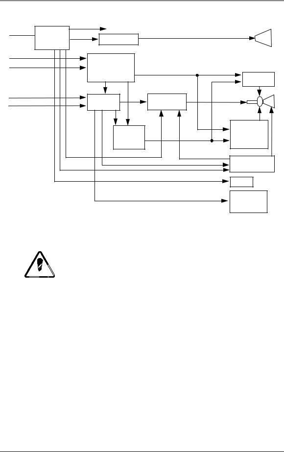
This chapter provides functional descriptions of the major assemblies in the Model 330, 340SC and 370SC projectors.
Emphasis is placed on a description of system components to the functional block level. A number of block diagrams are provided for user reference.
Figure 2-1 provides a block diagram overview of the HJT Model 330, 340SC and 370SC projectors. For simplicity, each major electronics assembly is shown with signal paths between appropriate functional units. Major physical and electronics assemblies will be described in more detail in the following sections of this chapter.
Model 330, 340SC and 370SC Service Manual |
2–1 |
Chapter 2—Functional Descriptions
|
|
Low Voltage |
|
|
|
|
System |
Power Supply |
|
Arc Lamp |
|
Line Voltage |
|
|
|
||
Power |
Lamp Ignitor |
|
|
||
|
|
|
|||
|
Supply |
|
|
|
|
RS 232 |
|
|
|
|
|
Infrared Remote |
System |
|
|
||
|
|
Controller |
|
Horizontal |
|
|
|
|
|
||
|
|
|
|
Deflection |
|
Channel 1 |
|
Video |
Video Output |
CRTs |
|
Channel 2 |
|
||||
|
Processor |
Amplifier |
|||
|
(3 each) |
||||
(R,G,B, H/V Sync) |
|||||
|
|
||||
|
|
|
|||
|
|
Raster |
|
Vertical |
|
|
|
|
Deflection |
||
|
|
Timing |
|
||
|
|
|
and |
||
|
|
Generator |
|
||
|
|
|
Convergence |
||
|
|
|
|
||
|
|
|
|
High Voltage |
|
|
|
|
|
Power Supply |
|
|
|
|
|
Fans |
|
|
|
|
|
Image Light |
|
|
|
|
|
Amplifiers |
|
|
|
|
|
(3 each |
|
Figure 2-1 Model 330, 340SC and 370SC System Block Diagrams
2.1 Cover and Base

 CAUTION! The covers for the HJT Model 330, 340SC and 370SC projectors must be installed for proper operation.
Operation of the projector, other than for maintenance, with the covers removed is not recommended and will void the projector warranty.
In addition to aesthetics, the covers on the Model 330, 340SC and 370SC projectors serve several functions. The covers are an integral part of the cooling system of the projector. Air intake filters are contained in the covers as are cooling fans. The covers provide the operator and audience with protection from the extremely bright light produced in the projector. The covers also serve to reduce the noise generated by operation of the projector. The UL approval is only valid with the covers installed since they provide the primary protection to prevent personnel from coming into contact with the high voltages and currents contained within the projector.
2–2 |
Model 330, 340SC, and 370SC Service Manual |
Chapter 2—Functional Descriptions
 WARNING!!! The HJT Model 330, 340SC and 370SC projectors use high voltages and high currents. Operation with covers removed exposes personnel to these dangerous conditions and may result in serious injury or death. No user-serviceable parts are contained within the projector. Refer all maintenance to only factory authorized and trained technicians.
The projector cover is a two-piece molded assembly. It is fastened to the projector frame by six (6) screws: two (2) on the rear cover; and four (4) on the front cover.
The fan intake side of the cover (right side) has filters on the intake vents. Periodic cleaning of the filters is required and should be performed in accordance with the procedure in this manual (Section 4.3). To avoid overheating the projector, ensure that the cover vent ports are free of obstructions at all times and that an adequate supply of fresh air is provided to the projector during operation.
2.2 External Power Requirements
The projectors require 208V to 240V, 50 Hz to 60 Hz, single-phase AC power. The units are equipped with an attached AC power cord and 3-prong twist lock plug (Model 330 and 340SC use Hubble Model 2323; Model 370SC uses Hubble Model 2623 or equivalent).

 CAUTION! Operation at voltages and frequencies outside of these listed parameters may cause damage to the projector and will void the warranty.
2.3 Electronics Systems Overview
The objective of this portion is to provide a good general understanding of the projector electronics. The understanding gained will enable service personnel to more effectively maintain the projector to produce the desired result—a great picture on the screen —and quality you can see.
The Electronics Systems portion of this manual is based on block diagrams. The diagrams used have been drawn with two purposes in mind. First, they are general enough to be able to gain an understanding of the overall function of the various components of the system. Second, the block diagrams contain enough detail to make them valuable as a troubleshooting tool should the need arise. Schematics are not used but, where necessary, simplified circuitry is shown to aid in understanding the capabilities and/or limitations of the system. Discussion of troubleshooting is included but is largely confined to symptoms and identification of failed assemblies.
The Hughes-JVC Model 330, 340SC and 370SC projectors are multi-sync projectors capable of data, graphics, and display from 15KHz to 90KHz
Model 330, 340SC and 370SC Service Manual |
2–3 |

Chapter 2—Functional Descriptions
horizontal and 45Hz to 120Hz vertical. The projected image is continuously variable from 6 ft to 60 ft over throw distances (varies by projector model) from 10 ft to over 360 ft. All HJT Series 300 projectors are capable of keystone, pincushion, and linearity correction. The projectors feature digital control of functions, including convergence, picture adjustments, switching and diagnostics. In addition, the projector provides the ability to control the relative brightness anywhere on the screen.
The capabilities of the Model 330, 340SC and 370SC projectors are provided by a sophisticated electronics system, which consists of power supplies, input/output devices, and various circuit boards, and using both analog and digital components to provide functionality with a simple user interface. The electronics systems are assembled in modular fashion for ease of removal or maintenance.
The Model 330, 340SC and 370SC Electronics System consists of:
System Controller Board;
Video Processor Board;
Video Amplifier Boards (3);
Raster Timing Generator Board;
Horizontal Deflection Board;
Vertical Deflection Board;
Lamp Ignitor;
System Power Supply;
High Voltage Power Supply.
There are also image and sync signal inputs, an LED display, two (2) RS-232 communication ports, and two (2) IR receivers for projector control.
The digital and analog circuits of the System Controller Board direct the operation of image and raster generation circuits as well as controlling the input/output and power supply operation of the HJT Model 330, 340SC and 370SC projector electronics systems.
The System Controller sets operating parameters of the system such as brightness and contrast, produces internal test patterns and generates on-screen overlays, and sets the timing for the raster generation to adjust phase, geometric corrections, uniformity corrections and convergence. The System Controller houses the program memory as well as the memory for all convergence and uniformity maps, and has the responsibility of controlling communication with the user, power to the other areas of the projector, and other necessary functions.
The Video Processor and Video Amplifiers select the desired input signal and process it to produce the CRT beam modulation necessary to produce an image on the raster.
2–4 |
Model 330, 340SC, and 370SC Service Manual |

Chapter 2—Functional Descriptions
The Raster Timing Generator provides timing signals to the System Controller Board, selects the appropriate incoming sync signal and produces the timing signals for controlling the geometry of the raster.
The Vertical and Horizontal Deflection Boards produce their respective sweep currents to drive the deflection yokes. The Vertical Deflection Board also houses the convergence amplifiers that drive correction coils.
The System Power Supply provides all DC power below 200V to the projector. This includes the supply to the arc lamp/ignitor and the supply to the High Voltage Power Supply.
The High Voltage Power Supply provides all voltages of 200V and higher. This includes all CRT bias voltages except the cathode.
Image and sync inputs arrive in the projector at the Video Processor Board. Inclusion of the Decoder Board is optional. User communication is accomplished by on-screen displays, LED display output, IR remote input, or RS232 Input/Output. All of these devices are separate from, but communicate directly with the System Controller Board.
The detailed functional description of the subassemblies are covered below in the following order:
1.System Power.
2.Card Cage and Circuit Boards.
3.CRT Assembly.
4.Arc Lamp.
2.4System Power
System Power Supply
The System Power Supply provides the connection between the external power source and the projector. The System Power Supply provides all internal DC power to the projector with the exception of that provided by the High Voltage Power Supply (Section 2.4.3). This includes the low voltage power to the electronics, the supply power to the HVPS, and the Arc Lamp power.
The System Power Supply is a AC-DC power supply with an input rectifier and protection circuit and several separate switchers; one (1) for Arc Lamp power, one
(1) for +5V Standby power, one (1) for +24V Standby power, and others for the other low voltages.
All of the power supply outputs are protected against overvoltage and overcurrent. Overcurrent protection is a foldback circuit that limits the output current by reducing the output voltage when an overcurrent condition is detected. An overvoltage condition at the output of the supply will cause the affected voltage to be shut down until input power is removed and reapplied.
Model 330, 340SC and 370SC Service Manual |
2–5 |
Chapter 2—Functional Descriptions
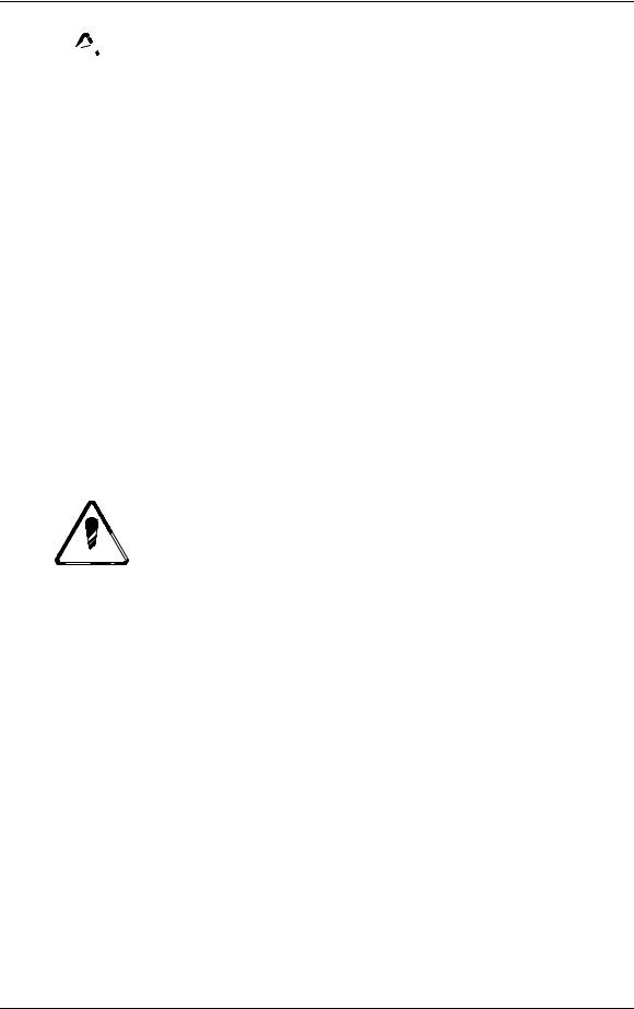
All of the SPS output voltages except Arc Lamp power are indicated by a LED display (see ). The LEDs are located on a bar-type display on the backplane at the left side of the card cage. The individual LEDs will be lit when the corresponding voltage is energized. The LEDs are wired to the SPS output power using only a current limiting resistor so when the LED is lit, it is an indication that there is a voltage present, not necessarily the correct voltage. To verify whether or not the voltage at the output is correct, a voltmeter must be used to probe the output connectors J500, J501, or J502.
+5V +5V +24V +6.3V +15V -15V +24V +48V +107V -200V
STB STB
Figure 2-2 Backplane Status Indicators.
A safety interlock switch is located on top of the power supply. The interlock switch shuts off the System Power Supply whenever the cover is removed. During normal operation with the cover installed, the switch is in the 'armed' position. When the rear cover is removed, the switch will be released and cause power to the projector to be interrupted. To run the unit without the cover installed, override the interlock switch by pulling it up into the 'service' position. When the cover is replaced, the switch will automatically be reset into the 'armed' position.
A circuit breaker is located on the right side of the System Power Supply. The circuit breaker serves to remove all power from the projector (except for the power at the input terminals) by switching it to the OFF position.

 CAUTION! The circuit breaker must be switched off, and the projector must be disconnected from AC power prior to performance of any maintenance, to ensure that all power is removed from the internal components of the projector.
Normal operation of the System Power Supply is as follows:
When external power is applied, +5V Standby will always be energized as will the internal SPS fans. +24V Standby power for operating the fans will be energized whenever the lamp or electronics are turned-on and five (5) minutes after the projector is shut down.
All other voltages are controlled by the power-up or power-down commands issued by the operator.
2–6 |
Model 330, 340SC, and 370SC Service Manual |
Chapter 2—Functional Descriptions
The Arc Lamp power supply is a current-controlled supply with an open circuit voltage of about 170V. When the Arc Lamp is operating at steady state, the power supply provides the current set by the technician. The output of the supply has a large capacitor that will, on initial ignition of the Arc Lamp, provide the very high initial current necessary to ionize the xenon gas in the lamp and sustain the arc. The current setpoint is initially set at the factory and must be reset by the technician whenever an Arc Lamp is replaced.
AC INPUT |
|
POWER |
|
|
|
|
|
|
STANDBY/ |
|
|
|
|
|
||||||
|
|
|
|
|
FACTOR |
|
|
|
|
|
|
|
|
|
|
|
|
|||
220-240vac |
|
|
|
|
|
|
|
|
|
|
|
|
|
|||||||
|
CORRECTION |
|
|
|
|
|
|
I/O CONTROL |
|
|
|
|
|
|||||||
|
|
|
|
|
|
|
|
J502 |
|
|||||||||||
50Hz |
|
|
|
|
|
|
|
|
|
|||||||||||
|
|
|
|
|
|
|
|
|
|
|
+5v, +24v |
|
|
|||||||
|
|
|
|
|
|
|
/FANENBL |
|
|
|
|
|
|
|
|
|
|
|
To |
|
From |
|
|
|
|
|
|
|
|
|
|
|
|
Backplane |
|||||||
|
|
|
|
|
|
|
|
|
||||||||||||
|
|
|
|
|
|
|
|
|
|
|
|
|
|
|
|
|
|
|||
|
|
|
|
|
|
|
|
|
|
|
|
|
|
|
|
|
|
|||
|
|
|
|
|
|
|
|
|
|
|
|
|
|
|
|
|||||
System |
|
|
|
|
|
|
|
|
|
|
|
|
LOW VOLTAGE |
|
J500 |
|
||||
Controller |
|
|
|
|
|
|
|
|
|
|
|
|
Power Supply |
|
|
|||||
|
|
|
|
|
|
|
|
|
|
|
|
|||||||||
|
|
J502 |
|
|
/LVPSNBL |
|
|
|
|
+5v,+6.3v,+-15v, |
|
|
|
|
|
|||||
|
|
|
|
|
|
|
|
|
|
|
|
|
||||||||
|
|
|
|
|
|
|
|
+24v,+48v,+107v |
|
|
|
|
|
|||||||
|
|
|
|
|
|
|
|
|
|
|
|
|
|
|
|
|
|
|
|
|
|
|
|
|
|
|
|
|
|
|
|
|
|
|
|
|
|
|
|
|
|
|
|
|
|
|
|
|
|
|
|
|
|
|
|
|
|
|
|
|
|
|
|
|
|
|
|
|
|
|
|
|
|
|
|
|
|
ARC LAMP |
|
|
|
|
To |
|
|
|
|
|
|
|
|
|
|
|
|
|
|
|
|
|
|
|
||
|
|
|
|
|
|
|
|
|
|
|
|
|
|
|
Power Supply |
|
J503 (-) |
Arc Lamp |
||
|
|
|
|
|
|
|
|
|
|
|
|
|
|
|
and Boost |
|
||||
|
|
|
|
|
|
|
|
|
|
|
|
|
|
|
|
J504 (+) |
Via |
|||
|
|
|
|
|
|
|
/ALENBL |
|
|
|
+22v/68a |
|
||||||||
|
|
|
|
|
|
|
|
|
|
|||||||||||
|
|
|
|
|
|
|
|
|
|
|
|
|
|
|
|
|
|
|
Ignitor |
|
|
|
|
|
|
|
|
|
|
|
|
|
|
|
|
+170v/1.0a |
|
|
|
|
|
|
|
|
|
|
|
|
|
|
|
|
|
|
|
|
|
|
|
|
||
|
|
|
|
|
|
|
|
|
|
|
|
|
|
|
|
|
|
|
|
|
Model 330. Model 340SC = +25V/80a; Model 370SC = +30V/100a.
Figure 2-3 System Power Supply Block Diagram.
Normal system power-up (Electronics and Lamp):
1.Upon receipt of Power-On command, SCB pulls /FANENBL and /ALENBL lines low.
2.+24V Standby and Arc Lamp power supplies turn on.
3.When Arc Lamp lights (run voltage sensed by a window comparator in the SPS), SPS pulls /LAMPLIT line low.
4.When SCB senses /LAMPLIT low, SCB pulls /LVPSNBL line low.
5.Low voltage supplies turn on.
6.SCB senses +5V supply at correct level and enters normal program sequence.
Lamp only power-up:
1.Upon receipt of Lamp-On command, SCB pulls /FANENBL and /ALENBL lines low.
Model 330, 340SC and 370SC Service Manual |
2–7 |

Chapter 2—Functional Descriptions
2.+24V Standby and Arc Lamp power supplies turn on.
3.When Arc Lamp lights (run voltage sensed by a window comparator in the SPS), SPS pulls /LAMPLIT line low.
4.SCB senses /LAMPLIT low and awaits further instructions.
Electronics only power-up:
1.Upon receipt of Electronics-On command, SCB pulls /FANENBL and /LVPSNBL lines low.
2.+24V Standby and Low voltage supplies turn on.
3.SCB senses +5V supply at correct level and enters normal program sequence, lamp can be turned on at any time.
Table 2-1 System Power Supply Voltage Distribution
|
F |
HV |
|
|
|
|
|
|
|
Arc |
|
Voltage |
a |
CRT |
SCB |
HDB |
VDB |
VPB |
RTG |
VAB |
Lamp/ |
||
PS |
|||||||||||
|
n |
|
|
|
|
|
|
|
Ignitor |
||
|
|
|
|
|
|
|
|
|
|||
|
|
|
|
|
|
|
|
|
|
||
+5v |
|
|
|
|
|
|
|
|
|
|
|
+5v Stb |
|
|
|
|
|
|
|
|
|
|
|
+6.3v |
|
|
|
|
|
|
|
|
|
|
|
+15v |
|
|
|
|
|
|
|
|
|
|
|
-15v |
|
|
|
|
|
|
|
|
|
|
|
+24v |
|
|
|
|
|
|
|
|
|
|
|
+24v Stb |
|
|
|
|
|
|
|
|
|
|
|
+48v |
|
|
|
|
|
|
|
|
|
|
|
+107v |
|
|
|
|
|
|
|
|
|
|
|
+170v |
|
|
|
|
|
|
|
|
|
|
|
|
|
|
|
|
|
|
|
|
|
|
|
2–8 |
Model 330, 340SC, and 370SC Service Manual |
Chapter 2—Functional Descriptions
*Current depends on projector model (see Table 0-1 in Safety Chapter). ** Model 340SC = 2000 Watts; Model 370SC = 3000 Watts.
Figure 2-4 System Power Supply Input/Output Diagram
Arc Lamp Ignitor
The ignitor consists of a step-up power supply, a spark gap, and a transformer. The Arc Lamp Ignitor is mounted under or next to the Arc Lamp. It provides the high voltage pulse necessary to ignite the Xenon Arc Lamp that is the illumination supply for the HJT Model 330, 340SC and 370SC projectors.
The System Power Supply’s Arc Lamp Supply section provides the necessary voltage to activate the ignitor and to sustain the arc in the Arc Lamp once it has been ignited. The SPS provides the power necessary to operate the ignitor.
The Ignitor is only active during the time between the Arc Lamp Power Supply energizing and the Arc Lamp igniting. During steady state operation and when the projector power is off, the ignitor is inactive.
Model 330, 340SC and 370SC Service Manual |
2–9 |
Chapter 2—Functional Descriptions
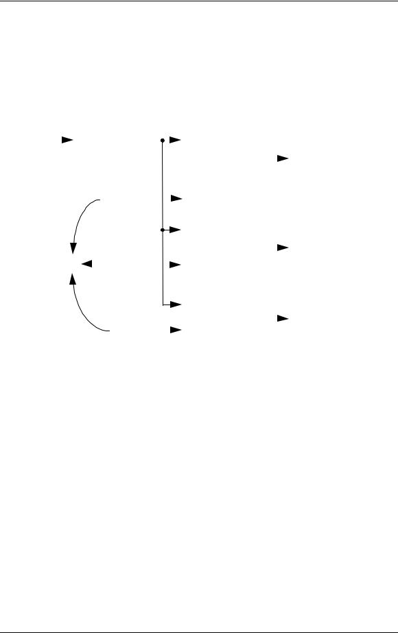
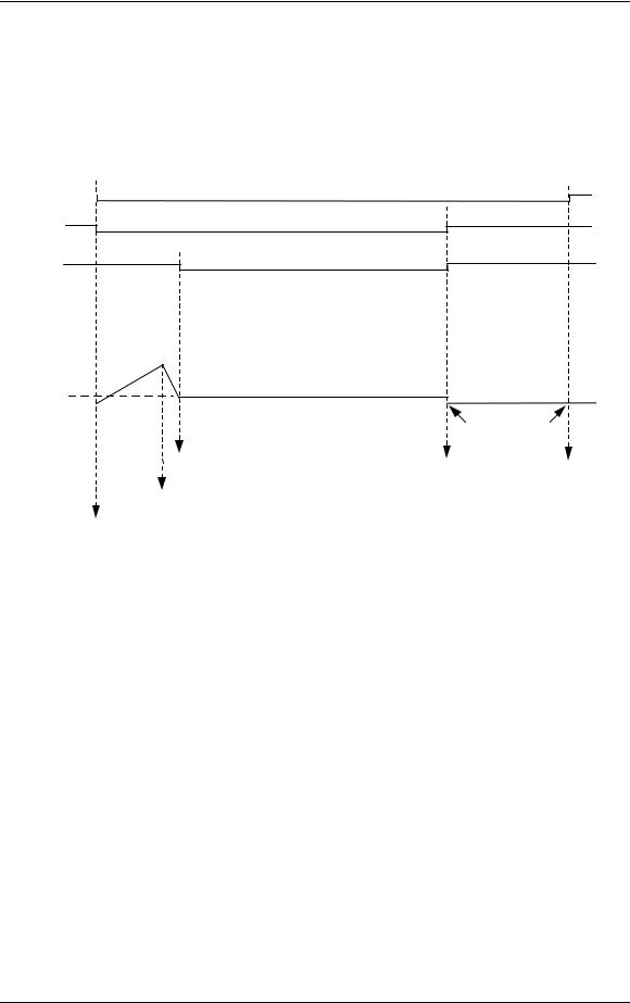
When the Arc Lamp supply first turns on, it supplies 170V to the ignitor. The ignitor then senses this voltage, activates it’s on-board supply, and produces a
1 S, 38KV pulse to the Arc Lamp. This pulse strikes an arc in the lamp. The Arc Lamp supply then provides the high current necessary to sustain the arc in the lamp. Refer to Figure 2-5 and the summary below for a description on the Arc Lamp and Ignitor timing.
/FANENBL
/ALENBL
/LAMPLIT
38 KV |
|
|
|
|
|
|
|
|
|
|
|
|
|
|
|
|
|
|
|
|
|
|
|
|
|
|
|
|
|
|
|
|
|
|
|
|
|
|
|
|
|
|
|
|
|
|
|
|
|
|
|
||||
170V |
|
|
|
|
|
|
|
|
|
|
|
|
|
|
|
|
|
|
|
|
|
|
|
||||
|
|
|
|
|
|
|
|
|
|
|
|
|
|
|
|
|
|
|
|
|
|||||||
22-30V* |
|
|
|
|
|
|
|
|
|
|
|
|
|
|
|
|
|
|
|
||||||||
0V |
1 |
2 |
|
|
|
|
5 |
|
|
||||||||||||||||||
|
|
|
|
|
|
|
|
|
3 |
|
|
|
|
6 |
|
CPU TIME-OUT |
|||||||||||
|
|
|
|
|
|
|
|
|
4 |
|
|
|
|
|
|
5-10 MINUTES |
|||||||||||
ARC LAMP ON |
LAMP-OFF |
FAN DISABLE |
|
||
|
COMMAND |
|
IGNITOR FIRES |
|
|
LAMP-ON COMMAND |
|
|
*22-30V depending on projector model.
Figure 2-5 Arc Lamp Ignitor Timing Diagram
Arc Lamp/Ignitor Timing Diagram Summary:
1.The operator powers Arc Lamp on. /ALENBL and /FANENBL from System Controller Board are pulled low. SPS receives /ALENBL from SCB and turns on the Arc Lamp PS.
2.Ignitor receives +170V boost voltage from the Arc Lamp PS.
3.Ignitor steps up the +170V boost voltage to a 1 sec pulse, approximately 38KV.
4.Arc Lamp ignites from the 38kV pulse.
5.High current (about 68-100A depending on projector model) begins through Arc Lamp and voltage drops to +22-30V (depending on projector model).
6./LAMPLIT signal goes to SCB to inform board that Arc Lamp is lit.
2-10 |
Model 330, 340SC, and 370SC Service Manual |
Chapter 2—Functional Descriptions
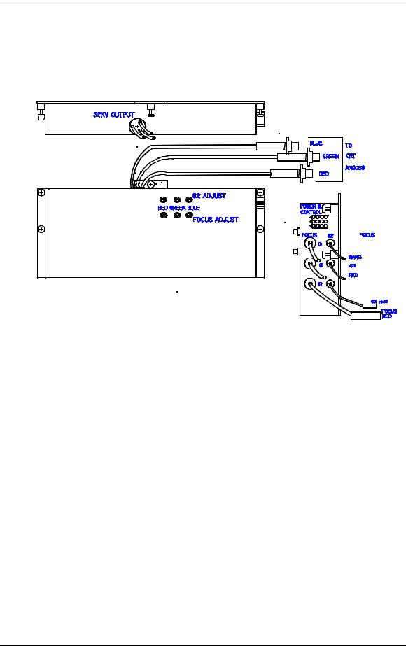
High Voltage Power Supply
The High Voltage Power Supply is a DC-DC converter (see Figures 2-6 and 2-7) and is located on the left side of the CRT housing. It provides all necessary voltages for the CRTs except the cathode drive, which comes from +107V from the SPS.
Figure 2-6 High Voltage Power Supply
Input power is +24V at 5A from the SPS. The input power is converted into the high voltage necessary to bias the CRTs.
The HVPS is controlled by an enable line (/HVEN) originating at the Video Processor Board. This enable line is controlled by logic that turns the HVPS off when there is a fault that could damage the CRTs. There are two (2) different conditions that could damage the HVPS:
1.If the +5V supply to the VPB is interrupted, the control and protection is compromised and the HVPS must be turned off.
2.If the cathode drive power is lost on one of the Video Amplifiers, the cathode current cannot be controlled and the HVPS is turned off.
3.Further details regarding this logic can be found in the functional description on the Video Processor Board in Section 2.6.4.
Model 330, 340SC and 370SC Service Model |
2-11 |
Chapter 2—Functional Descriptions
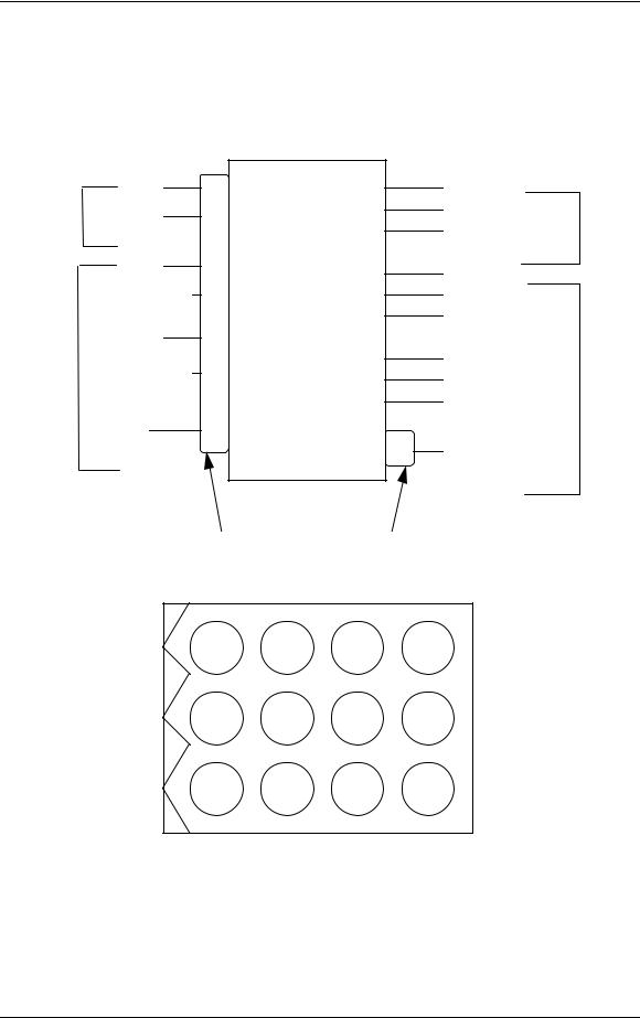
The HVPS provides several voltages to the CRTs:
|
|
Anode |
|
|
|
Grid 1 |
|
|
|
Grid 2 |
|
|
|
Focus |
|
+24v |
2 |
|
|
GROUND |
3 |
|
|
HDFOCUS |
11 |
High |
|
HDFOCUS RTN |
8 |
Voltage |
|
VDFOCUS |
12 |
Power |
|
Supply |
|||
VDFOCUS RTN |
9 |
||
|
|||
/HVEN |
7 |
|
|
|
|
6 |
|
|
|
(Pins 1,4,5,10 not used) |
RED ANODE GREEN ANODE BLUE ANODE
RED FOCUS GREEN FOCUS BLUE FOCUS
RED G2
GREEN G2
BLUE G2
-200v
Power and Control Connector
Figure 2-7 High Voltage Power Supply Input/Output Diagram
3 6 9 12
2 5 8 11
1 4 7 10
Figure 2-8 HVPS Power and Control Connector Jack, J603
2-12 |
Model 330, 340SC, and 370SC Service Manual |

Chapter 2—Functional Descriptions
CRT anode voltages are not user controllable. They are fixed at 32KV with a maximum output of 2.1mA total or 0.7mA per CRT. The anode voltage is the primary acceleration voltage for the CRT. Other bias voltages (screen grid, G2, and control grid, G1) are used to control the level of beam current. The anode voltage is routed out of the top of the HVPS, into the CRT housing to three (3) bulkhead connectors. From there, the anode wires on the CRTs route the anode voltage directly to the CRT. The anode voltages are overvoltage and overcurrent protected in the event of short circuits or CRT arcing.
Focus voltage (called Electronic Focus) is a modulated DC voltage. The DC level is set by the user during initial setup to focus the CRT electron beam. The Electronic Focus controls are located on the left side of the HVPS (see appropriate model Operator’s Manual). There are three (one for each color) ¾ turn pots for adjusting the Electronic Focus. Of the six (6) pots found on the HVPS, the bottom three (3) are for focus while the top three (3) are for G2 adjustment (Section 3.10). The DC voltage is modulated within the HVPS using the HDFOCUS and VDFOCUS input signals. VDFOCUS is the vertical dynamic focus signal, which is a waveform with parabolic shape at the vertical sweep frequency. HDFOCUS is the horizontal dynamic focus signal. It is a combination of the vertical dynamic focus signal and a parabolic waveform at the horizontal sweep rate. These two (2) signals are combined in the HVPS to form a composite dynamic focus signal. Dynamic focus is necessary to ensure that the CRT electron beam is converged to a point as the beam sweeps across the CRT face. Since the CRT faceplate is flat, the raster sweep causes a varying path length for the electron beam. This means the focus voltage must be varied as the raster is traced. Focus voltage cannot be conveniently measured during normal operation.
G2 screen grid voltage is a DC voltage that is set by the user. The three (3) adjustment controls, one for each color, consist of ¾ turn pots and are located on the left side of the HVPS immediately above the focus controls. This voltage is set during initial projector setup to adjust the black level on the screen (see appropriate model Operator’s Manual). The G2 voltage sets the bias on the screen grid of the CRT and is normally used to set the cutoff level. However, since the HJT light valve requires a non-zero input to produce a just-cut-off image on the screen, G2 is set to produce a slightly greater-than-black raster on the CRT. The G2 is adjustable from 100V to 1400V individually by color. The actual operating level will be near 1200V. G2 voltage cannot be conveniently measured during normal operation.
-200V is the supply to the control grid (G1) of the CRTs through the Video Amplifier Board. This voltage is not user controllable. The -200V is the only output voltage from the HVPS that goes to the backplane of the projector to be routed to the Video Amplifier, and uses the rear-most LED of the backplane LED bar for indication.
-200V is the only convenient means of directly observing whether or not the HVPS is turned on, either by observing the indicator LED on the backplane, or by probing the control connector with a voltmeter.
Model 330, 340SC and 370SC Service Model |
2-13 |

Chapter 2—Functional Descriptions
As with the other indicators on that LED bar, the LED is in series with current limiting resistor, so a lit LED indicates only the presence of a voltage, not necessarily the correct voltage.
The control grid, G1, voltage is regulated to -81V during normal operation. During blanking, G1 is pulled to -111V. When the CRTs are disabled for protection, G1 is pulled to its maximum negative level of -200V, which can be measured, at the control connector, pin 6.
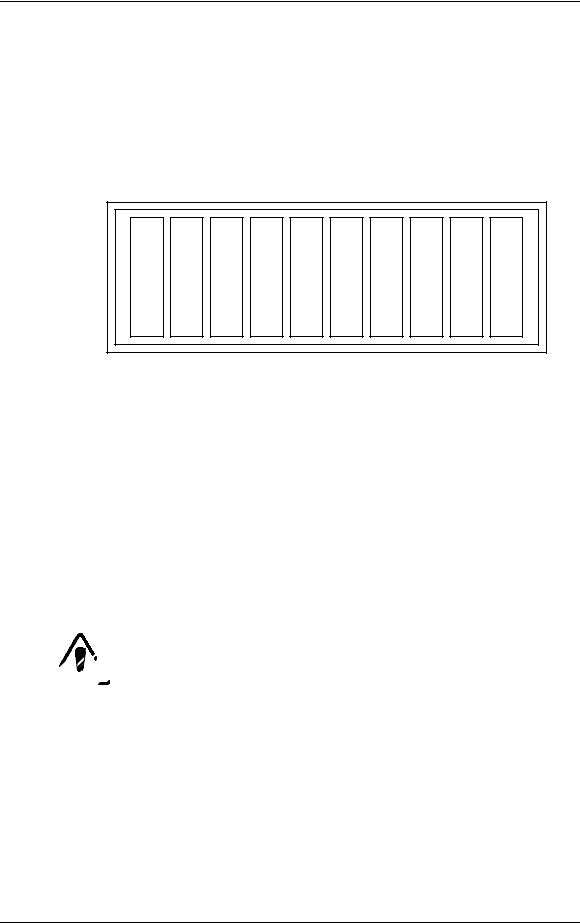
2.5 Card Cage
The Card Cage provides support and protection for five (5) circuit boards, the Phase Locked Loop and the optional Decoder Board in the HJT Model 330, 340SC and 370SC projectors. The five-(5) circuit boards are, from rear to front, the VPB, RTG, SCB, VDB, and HDB. Each circuit board has it's own keyed slot. A circuit board cannot easily be plugged into the wrong slot since the connectors will not match up.
Horizontal Deflection Board |
|
(HDB) |
P/N 102523 |
|
|
|
|
Vertical Deflection Board |
|
(VDB) |
P/N 102521 |
|
|
|
|
System Controller Board |
|
(SCB) |
P/N 104668 |
|
|
|
|
Raster Timing Generator |
|
(RTG) |
P/N 100568 |
and Phase Locked Loop |
|
(PLL) |
|
|
|
|
|
Video Processor Board |
|
(VPB) |
P/N 104672 |
and optional Decoder Board |
|
|
|
|
|
|
|
|
|
|
|
Figure 2-9 |
Electronics Card Cage |
|
|
Four (4) fans on the right side of the card cage cool the circuit cards in the card cage. These fans are energized by the +24V standby power from the SPS. They start when either the Arc Lamp or the electronics are powered up and run for approximately five (5) minutes after the projector is shut down.
The five-(5) cards in the card cage are held into position by both the friction of the connectors and by a circuit board retaining bar. The circuit board retaining bar should always be installed during projector operation.
A lightweight top cover is included with the card cage. Eight (8) screws secure the cover. The cover provides for direction of air flow and for physical protection of the circuit cards contained in the card cage. The cover should always be installed when the projector is in operation to ensure adequate cooling of the circuit cards and to prevent foreign materials from falling into the electronics.
2-14 |
Model 330, 340SC, and 370SC Service Manual |

Chapter 2—Functional Descriptions
The card cage is hinged in the rear to allow it to be folded backward for access to the CRT housing (when folding the card cage backward be sure that nothing is plugged into the rear electronic jacks or the plugs could be severely damaged). During normal operation, the card cage should be in its upright position to ensure proper cooling of the CRT enclosure.
A holddown screw is provided to secure the card cage and prevent it from rotating backward during shipping or when the projector is mounted in an upwardpointing position. The holddown screw is located on the lower, front, right corner of the card cage.
The rear panel of the card cage provides mounting for the projector controls. The VPB, which receives all image and sync inputs, is secured to the rear panel by four screws. The RS-232 control connectors and the IR receiver and repeater inputs as well as the LED dot matrix status display are located on the lower left of the rear panel. The projector model and serial numbers are also found on the rear panel.
2.6 Circuit Boards
The Model 330, 340SC and 370SC projectors have a total of twelve (12) accessible circuit boards. Seven (7) boards are located within the card cage (Figure 2-9) and five (5) are located outside the card cage (Table 2-2).
Table 2-2 Circuit Boards Outside Card Cage
No. |
Description |
330 |
340SC |
370SC |
1 |
Ignitor |
102083 |
102207 |
104475 |
3 |
Video Amp Boards (VABS) |
103567 |
103567 |
103567 |
1 |
Backplane |
100571 |
100571 |
100571 |
|
|
|
|
|
Each circuit board can be replaced individually except the Backplane board and the PLL. The PLL is replaced with the RTG as a unit. The Ignitor was previously described in Section 2.4.2. The circuit boards covered in this Section are listed in Table 2-3.
Table 2-3 Circuit Boards
Page |
Circuit Board |
|
P/N |
|
|
|
|
|
|
|
|
|
|
|
2-18 |
Raster Timing Generator |
(RTG) |
100568 |
and PLL |
2-26 |
Horizontal Deflection Board |
(HDB) |
102523 |
|
2-34 |
Vertical Deflection Board |
(VDB) |
102521 |
|
2-44 |
Video Processor Board |
(VPB) |
104672 |
|
|
and optional Decoder Board |
|
|
|
2-55 |
Video Amplifier Board |
(VAB) |
103567 |
|
2-58 |
System Controller Board |
(SCB) |
104668 |
|
2-70 |
Backplane Board |
|
100571 |
|
|
|
|
|
|
Model 330, 340SC and 370SC Service Model |
2-15 |

Chapter 2—Functional Descriptions
Figure 2-10 on the following page provides an overall view of how the raster is produced. Details on the individual PCBs are provided in separate sections in this chapter.
2-16 |
Model 330, 340SC, and 370SC Service Manual |

Chapter 2—Functional Description
Figure 2-10 Raster Generation Block Diagram
Model 330, 340SC and 370SC Service Manual |
2-17 |
Chapter 2—Functional Descriptions
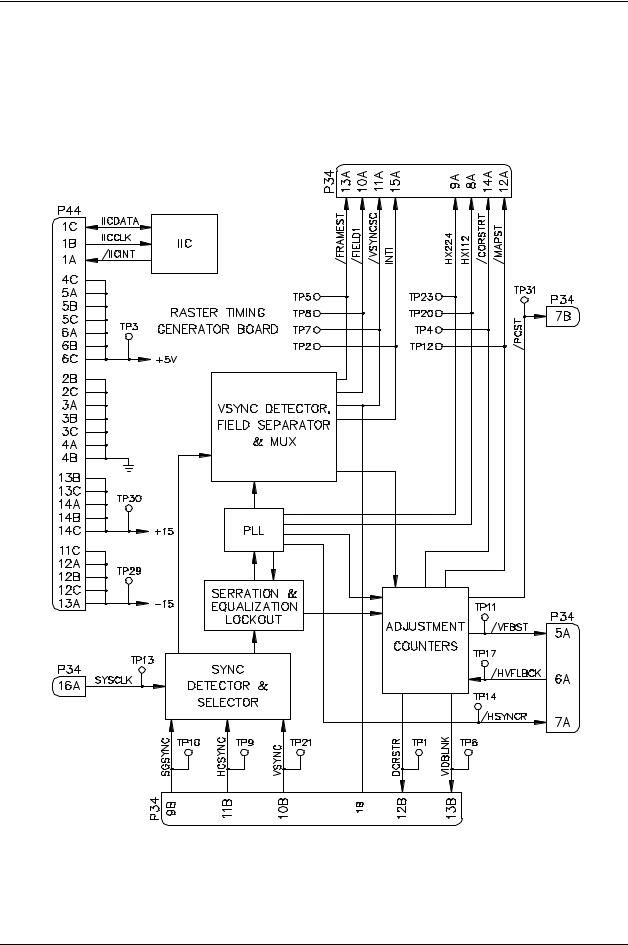
Raster Timing Generator Board (RTG) p/n 100568
The Raster Timing Generator board is located in the electronics card cage and plugs into the backplane. It is the second board from the rear of the card cage and consists of a main board and the PLL daughter board (see Figure 2-11). The PLL board must be installed for the projector to operate.
Figure 2-11 Raster Timing Generator Block Diagram
2-18 |
Model 330. 340SC, and 370SC Service Manual |
 Loading...