


 Loading...
Complete Hardware Guide for EX2200 Ethernet Switches
Published: 2010-12-07
Revision 4
Copyright © 2010, Juniper Networks, Inc.

Juniper Networks, Inc.
1194 North Mathilda Avenue Sunnyvale, California 94089 USA
408-745-2000 www.juniper.net
ThisproductincludestheEnvoySNMPEngine,developedbyEpilogueTechnology,anIntegratedSystemsCompany. Copyright©1986-1997, Epilogue Technology Corporation. All rights reserved. This program and its documentation were developed at private expense, and no part of them is in the public domain.
This product includes memory allocation software developed by Mark Moraes, copyright © 1988, 1989, 1993, University of Toronto.
This product includes FreeBSD software developed by the University of California, Berkeley, and its contributors. All of the documentation and software included in the 4.4BSD and 4.4BSD-Lite Releases is copyrighted by the Regents of the University of California. Copyright © 1979, 1980, 1983, 1986, 1988, 1989, 1991, 1992, 1993, 1994. The Regents of the University of California. All rights reserved.
GateD software copyright © 1995, the Regents of the University. All rights reserved. Gate Daemon was originated and developed through release 3.0 by Cornell University and its collaborators. Gated is based on Kirton’s EGP, UC Berkeley’s routing daemon (routed), and DCN’s HELLO routing protocol. Development of Gated has been supported in part by the National Science Foundation. Portions of the GateD software copyright © 1988, Regents of the University of California. All rights reserved. Portions of the GateD software copyright © 1991, D. L. S. Associates.
This product includes software developed by Maker Communications, Inc., copyright © 1996, 1997, Maker Communications, Inc.
Juniper Networks, Junos, Steel-Belted Radius, NetScreen, and ScreenOS are registered trademarks of Juniper Networks, Inc. in the United States and other countries. The Juniper Networks Logo, the Junos logo, and JunosE are trademarks of Juniper Networks, Inc. All other trademarks, service marks, registered trademarks, or registered service marks are the property of their respective owners.
Juniper Networks assumes no responsibility for any inaccuracies in this document. Juniper Networks reserves the right to change, modify, transfer, or otherwise revise this publication without notice.
Products made or sold by Juniper Networks or components thereof might be covered by one or more of the following patents that are owned by or licensed to Juniper Networks: U.S. Patent Nos. 5,473,599, 5,905,725, 5,909,440, 6,192,051, 6,333,650, 6,359,479, 6,406,312, 6,429,706, 6,459,579, 6,493,347, 6,538,518, 6,538,899, 6,552,918, 6,567,902, 6,578,186, and 6,590,785.
Complete Hardware Guide for EX2200 Ethernet Switches
Copyright © 2010, Juniper Networks, Inc.
All rights reserved. Printed in USA.
Writing: Appumon Joseph, Aviva Garrett, Greg Houde, Hemraj Rao S, Hareesh Kumar K N, Keldyn West, Shikha Kalra, Steve Levine Editing: Cindy Martin, Rajan V K
Illustration: Faith Bradford Brown Cover Design:
Revision History
17 February 2010—Revision 1 May 2010—Revision 2 August 2010—Revision 3 December 2010—Revision 4
The information in this document is current as of the date listed in the revision history.
YEAR 2000 NOTICE
Juniper Networks hardware and software products are Year 2000 compliant. The Junos OS has no known time-related limitations through the year 2038. However, the NTP application is known to have some difficulty in the year 2036.
SOFTWARE LICENSE
ii |
Copyright © 2010, Juniper Networks, Inc. |

The terms and conditions for using this software are described in the software license contained in the acknowledgment to your purchase order or, to the extent applicable, to any reseller agreement or end-user purchase agreement executed between you and Juniper Networks. By using this software, you indicate that you understand and agree to be bound by those terms and conditions.
Generally speaking, the software license restricts the manner in which you are permitted to use the software and may contain prohibitions against certain uses. The software license may state conditions under which the license is automatically terminated. You should consult the license for further details.
For complete product documentation, please see the Juniper Networks Web site at www.juniper.net/techpubs.
Copyright © 2010, Juniper Networks, Inc. |
iii |

END USER LICENSE AGREEMENT
READ THIS END USER LICENSE AGREEMENT (“AGREEMENT”) BEFORE DOWNLOADING, INSTALLING, OR USING THE SOFTWARE.
BY DOWNLOADING, INSTALLING, OR USING THE SOFTWARE OR OTHERWISE EXPRESSING YOUR AGREEMENT TO THE TERMS CONTAINED HEREIN, YOU (AS CUSTOMER OR IF YOU ARE NOT THE CUSTOMER, AS A REPRESENTATIVE/AGENT AUTHORIZED TO BINDTHECUSTOMER)CONSENTTOBEBOUNDBYTHISAGREEMENT. IFYOUDONOTORCANNOTAGREETOTHETERMSCONTAINED HEREIN, THEN (A) DO NOT DOWNLOAD, INSTALL, OR USE THE SOFTWARE, AND (B) YOU MAY CONTACT JUNIPER NETWORKS REGARDING LICENSE TERMS.
1.The Parties. The parties to this Agreement are (i) Juniper Networks, Inc. (if the Customer’s principal office is located in the Americas) or JuniperNetworks(Cayman)Limited(iftheCustomer’sprincipalofficeislocatedoutsidetheAmericas)(suchapplicableentitybeingreferred tohereinas“Juniper”),and(ii)thepersonororganizationthatoriginallypurchasedfromJuniperoranauthorizedJuniperresellertheapplicable license(s) for use of the Software (“Customer”) (collectively, the “Parties”).
2.The Software. In this Agreement, “Software” means the program modules and features of the Juniper or Juniper-supplied software, for which Customer has paid the applicable license or support fees to Juniper or an authorized Juniper reseller, or which was embedded by Juniper in equipment which Customer purchased from Juniper or an authorized Juniper reseller. “Software” also includes updates, upgrades and new releases of such software. “Embedded Software” means Software which Juniper has embedded in or loaded onto the Juniper equipment and any updates, upgrades, additions or replacements which are subsequently embedded in or loaded onto the equipment.
3.LicenseGrant. Subjecttopaymentoftheapplicablefeesandthelimitationsandrestrictionssetforthherein,JunipergrantstoCustomer a non-exclusive and non-transferable license, without right to sublicense, to use the Software, in executable form only, subject to the following use restrictions:
a.Customer shall use Embedded Software solely as embedded in, and for execution on, Juniper equipment originally purchased by Customer from Juniper or an authorized Juniper reseller.
b.Customer shall use the Software on a single hardware chassis having a single processing unit, or as many chassis or processing units for which Customer has paid the applicable license fees; provided, however, with respect to the Steel-Belted Radius or Odyssey Access Client software only, Customer shall use such Software on a single computer containing a single physical random access memory space and containing any number of processors. Use of the Steel-Belted Radius or IMS AAA software on multiple computers or virtual machines (e.g., Solaris zones) requires multiple licenses, regardless of whether such computers or virtualizations are physically contained on a single chassis.
c.Product purchase documents, paper or electronic user documentation, and/or the particular licenses purchased by Customer may specifylimitstoCustomer’suseoftheSoftware.Suchlimitsmayrestrictusetoamaximumnumberofseats,registeredendpoints,concurrent users, sessions, calls, connections, subscribers, clusters, nodes, realms, devices, links, ports or transactions, or require the purchase of separate licenses to use particular features, functionalities, services, applications, operations, or capabilities, or provide throughput, performance, configuration, bandwidth, interface, processing, temporal, or geographical limits. In addition, such limits may restrict the use of the Software to managing certain kinds of networks or require the Software to be used only in conjunction with other specific Software. Customer’s use of the Software shall be subject to all such limitations and purchase of all applicable licenses.
d.For any trial copy of the Software, Customer’s right to use the Software expires 30 days after download, installation or use of the Software. Customer may operate the Software after the 30-day trial period only if Customer pays for a license to do so. Customer may not extend or create an additional trial period by re-installing the Software after the 30-day trial period.
e.The Global Enterprise Edition of the Steel-Belted Radius software may be used by Customer only to manage access to Customer’s enterprise network. Specifically, service provider customers are expressly prohibited from using the Global Enterprise Edition of the Steel-Belted Radius software to support any commercial network access services.
The foregoing license is not transferable or assignable by Customer. No license is granted herein to any user who did not originally purchase the applicable license(s) for the Software from Juniper or an authorized Juniper reseller.
4. Use Prohibitions. Notwithstanding the foregoing, the license provided herein does not permit the Customer to, and Customer agrees not to and shall not: (a) modify, unbundle, reverse engineer, or create derivative works based on the Software; (b) make unauthorized copies of the Software (except as necessary for backup purposes); (c) rent, sell, transfer, or grant any rights in and to any copy of the Software,inanyform,toanythirdparty;(d)removeanyproprietarynotices,labels,ormarksonorinanycopyoftheSoftwareoranyproduct in which the Software is embedded; (e) distribute any copy of the Software to any third party, including as may be embedded in Juniper equipmentsoldinthesecondhandmarket;(f)useany‘locked’orkey-restrictedfeature,function,service,application,operation,orcapability without first purchasing the applicable license(s) and obtaining a valid key from Juniper, even if such feature, function, service, application, operation, or capability is enabled without a key; (g) distribute any key for the Software provided by Juniper to any third party; (h) use the
iv |
Copyright © 2010, Juniper Networks, Inc. |

Software in any manner that extends or is broader than the uses purchased by Customer from Juniper or an authorized Juniper reseller; (i) use Embedded Software on non-Juniper equipment; (j) use Embedded Software (or make it available for use) on Juniper equipment that the Customer did not originally purchase from Juniper or an authorized Juniper reseller; (k) disclose the results of testing or benchmarking of the Software to any third party without the prior written consent of Juniper; or (l) use the Software in any manner other than as expressly provided herein.
5.Audit. Customer shall maintain accurate records as necessary to verify compliance with this Agreement. Upon request by Juniper, Customer shall furnish such records to Juniper and certify its compliance with this Agreement.
6.Confidentiality. The Parties agree that aspects of the Software and associated documentation are the confidential property of Juniper. As such, Customer shall exercise all reasonable commercial efforts to maintain the Software and associated documentation in confidence, which at a minimum includes restricting access to the Software to Customer employees and contractors having a need to use the Software for Customer’s internal business purposes.
7.Ownership. Juniper and Juniper’s licensors, respectively, retain ownership of all right, title, and interest (including copyright) in and to the Software, associated documentation, and all copies of the Software. Nothing in this Agreement constitutes a transfer or conveyance of any right, title, or interest in the Software or associated documentation, or a sale of the Software, associated documentation, or copies of the Software.
8.Warranty, Limitation of Liability, Disclaimer of Warranty. The warranty applicable to the Software shall be as set forth in the warranty statementthataccompaniestheSoftware(the“WarrantyStatement”).NothinginthisAgreementshallgiverisetoanyobligationtosupport the Software. Support services may be purchased separately. Any such support shall be governed by a separate, written support services agreement. TO THE MAXIMUM EXTENT PERMITTED BY LAW, JUNIPER SHALL NOT BE LIABLE FOR ANY LOST PROFITS, LOSS OF DATA, ORCOSTSORPROCUREMENTOFSUBSTITUTEGOODSORSERVICES,ORFORANYSPECIAL,INDIRECT,ORCONSEQUENTIALDAMAGES ARISINGOUTOFTHISAGREEMENT,THESOFTWARE,ORANYJUNIPERORJUNIPER-SUPPLIEDSOFTWARE.INNOEVENTSHALLJUNIPER BE LIABLE FOR DAMAGES ARISING FROM UNAUTHORIZED OR IMPROPER USE OF ANY JUNIPER OR JUNIPER-SUPPLIED SOFTWARE.
EXCEPT AS EXPRESSLY PROVIDED IN THE WARRANTY STATEMENT TO THE EXTENT PERMITTED BY LAW, JUNIPER DISCLAIMS ANY AND ALL WARRANTIES IN AND TO THE SOFTWARE (WHETHER EXPRESS, IMPLIED, STATUTORY, OR OTHERWISE), INCLUDING ANY IMPLIED WARRANTY OF MERCHANTABILITY, FITNESS FOR A PARTICULAR PURPOSE, OR NONINFRINGEMENT. IN NO EVENT DOES JUNIPER WARRANT THAT THE SOFTWARE, OR ANY EQUIPMENT OR NETWORK RUNNING THE SOFTWARE, WILL OPERATE WITHOUT ERROR OR INTERRUPTION, OR WILL BE FREE OF VULNERABILITY TO INTRUSION OR ATTACK. In no event shall Juniper’s or its suppliers’ or licensors’ liability to Customer, whether in contract, tort (including negligence), breach of warranty, or otherwise, exceed the price paid by Customer for the Software that gave rise to the claim, or if the Software is embedded in another Juniper product, the price paid by Customer for such other product. Customer acknowledges and agrees that Juniper has set its prices and entered into this Agreement in reliance upon the disclaimers of warranty and the limitations of liability set forth herein, that the same reflect an allocation of risk between the Parties (including the risk that a contract remedy may fail of its essential purpose and cause consequential loss), and that the same form an essential basis of the bargain between the Parties.
9.Termination. Any breach of this Agreement or failure by Customer to pay any applicable fees due shall result in automatic termination of the license granted herein. Upon such termination, Customer shall destroy or return to Juniper all copies of the Software and related documentation in Customer’s possession or control.
10.Taxes. All license fees payable under this agreement are exclusive of tax. Customer shall be responsible for paying Taxes arising from the purchase of the license, or importation or use of the Software. If applicable, valid exemption documentation for each taxing jurisdiction shall be provided to Juniper prior to invoicing, and Customer shall promptly notify Juniper if their exemption is revoked or modified. All payments made by Customer shall be net of any applicable withholding tax. Customer will provide reasonable assistance to Juniper in connection with such withholding taxes by promptly: providing Juniper with valid tax receipts and other required documentation showing Customer’s payment of any withholding taxes; completing appropriate applications that would reduce the amount of withholding tax to be paid; and notifying and assisting Juniper in any audit or tax proceeding related to transactions hereunder. Customer shall comply with all applicable tax laws and regulations, and Customer will promptly pay or reimburse Juniper for all costs and damages related to any liability incurred by Juniper as a result of Customer’s non-compliance or delay with its responsibilities herein. Customer’s obligations under this Section shall survive termination or expiration of this Agreement.
11.Export. Customer agrees to comply with all applicable export laws and restrictions and regulations of any United States and any applicable foreign agency or authority, and not to export or re-export the Software or any direct product thereof in violation of any such restrictions, laws or regulations, or without all necessary approvals. Customer shall be liable for any such violations. The version of the Software supplied to Customer may contain encryption or other capabilities restricting Customer’s ability to export the Software without an export license.
Copyright © 2010, Juniper Networks, Inc. |
v |

12.Commercial Computer Software. The Software is “commercial computer software” and is provided with restricted rights. Use, duplication, or disclosure by the United States government is subject to restrictions set forth in this Agreement and as provided in DFARS 227.7201 through 227.7202-4, FAR 12.212, FAR 27.405(b)(2), FAR 52.227-19, or FAR 52.227-14(ALT III) as applicable.
13.Interface Information. To the extent required by applicable law, and at Customer's written request, Juniper shall provide Customer with the interface information needed to achieve interoperability between the Software and another independently created program, on payment of applicable fee, if any. Customer shall observe strict obligations of confidentiality with respect to such information and shall use such information in compliance with any applicable terms and conditions upon which Juniper makes such information available.
14.ThirdPartySoftware. Any licensor of Juniper whose software is embedded in the Software and any supplier of Juniper whose products or technology are embedded in (or services are accessed by) the Software shall be a third party beneficiary with respect to this Agreement, and such licensor or vendor shall have the right to enforce this Agreement in its own name as if it were Juniper. In addition, certain third party software may be provided with the Software and is subject to the accompanying license(s), if any, of its respective owner(s). To the extent portions of the Software are distributed under and subject to open source licenses obligating Juniper to make the source code for such portions publicly available (such as the GNU General Public License (“GPL”) or the GNU Library General Public License (“LGPL”)), Juniper will make such source code portions (including Juniper modifications, as appropriate) available upon request for a period of up to three years from the date of distribution. Such request can be made in writing to Juniper Networks, Inc., 1194 N. Mathilda Ave., Sunnyvale, CA 94089, ATTN: General Counsel. You may obtain a copy of the GPL at http://www.gnu.org/licenses/gpl.html, and a copy of the LGPL at http://www.gnu.org/licenses/lgpl.html .
15.Miscellaneous. This Agreement shall be governed by the laws of the State of California without reference to its conflicts of laws principles. The provisions of the U.N. Convention for the International Sale of Goods shall not apply to this Agreement. For any disputes arising under this Agreement, the Parties hereby consent to the personal and exclusive jurisdiction of, and venue in, the state and federal courts within Santa Clara County, California. This Agreement constitutes the entire and sole agreement between Juniper and the Customer with respect to the Software, and supersedes all prior and contemporaneous agreements relating to the Software, whether oral or written (including any inconsistent terms contained in a purchase order), except that the terms of a separate written agreement executed by an authorized Juniper representative and Customer shall govern to the extent such terms are inconsistent or conflict with terms contained herein. No modification to this Agreement nor any waiver of any rights hereunder shall be effective unless expressly assented to in writing by the party to be charged. If any portion of this Agreement is held invalid, the Parties agree that such invalidity shall not affect the validity of the remainder of this Agreement. This Agreement and associated documentation has been written in the English language, and the Parties agree that the English version will govern. (For Canada: Les parties aux présentés confirment leur volonté que cette convention de même que tous les documents y compris tout avis qui s'y rattaché, soient redigés en langue anglaise. (Translation: The parties confirm that this Agreement and all related documentation is and will be in the English language)).
vi |
Copyright © 2010, Juniper Networks, Inc. |

Table of Contents
About This Topic Collection . . . . . . . . . . . . . . . . . . . . . . . . . . . . . . . . . . . . . . . . . xv
How to Use This Guide . . . . . . . . . . . . . . . . . . . . . . . . . . . . . . . . . . . . . . . . . . . . . . . xv
List of EX Series Guides for Junos OS Release 10.4 . . . . . . . . . . . . . . . . . . . . . . . . . xv
Downloading Software . . . . . . . . . . . . . . . . . . . . . . . . . . . . . . . . . . . . . . . . . . . . . . xvii
Documentation Symbols Key . . . . . . . . . . . . . . . . . . . . . . . . . . . . . . . . . . . . . . . . xviii
Documentation Feedback . . . . . . . . . . . . . . . . . . . . . . . . . . . . . . . . . . . . . . . . . . . . xix
Requesting Technical Support . . . . . . . . . . . . . . . . . . . . . . . . . . . . . . . . . . . . . . . . . xx
Self-Help Online Tools and Resources . . . . . . . . . . . . . . . . . . . . . . . . . . . . . . . xx
Opening a Case with JTAC . . . . . . . . . . . . . . . . . . . . . . . . . . . . . . . . . . . . . . . . . xx
Part 1 |
Switch and Components Overview and Specifications |
|
Chapter 1 |
EX2200 Switch Overview . . . . . . . . . . . . . . . . . . . . . . . . . . . . . . . . . . . . . . . . . . |
. 3 |
|
EX2200 Switches Hardware Overview . . . . . . . . . . . . . . . . . . . . . . . . . . . . . . . . . . |
. 3 |
|
EX2200 Switches . . . . . . . . . . . . . . . . . . . . . . . . . . . . . . . . . . . . . . . . . . . . . . . |
. 3 |
|
Uplink Ports . . . . . . . . . . . . . . . . . . . . . . . . . . . . . . . . . . . . . . . . . . . . . . . . . . . . |
. 3 |
|
Power over Ethernet (PoE) Ports . . . . . . . . . . . . . . . . . . . . . . . . . . . . . . . . . . . |
. 4 |
|
EX2200 Switch Models . . . . . . . . . . . . . . . . . . . . . . . . . . . . . . . . . . . . . . . . . . . . . . |
. 4 |
|
Chassis Physical Specifications for EX2200 Switches . . . . . . . . . . . . . . . . . . . . . . |
. 5 |
|
Front Panel of an EX2200 Switch . . . . . . . . . . . . . . . . . . . . . . . . . . . . . . . . . . . . . . |
. 5 |
|
Rear Panel of an EX2200 Switch . . . . . . . . . . . . . . . . . . . . . . . . . . . . . . . . . . . . . . |
. 6 |
|
EX2200 Switch Hardware and CLI Terminology Mapping . . . . . . . . . . . . . . . . . . . |
. 7 |
Chapter 2 |
Component Descriptions . . . . . . . . . . . . . . . . . . . . . . . . . . . . . . . . . . . . . . . . . . |
. 11 |
|
Chassis Status LEDs in EX2200 Switches . . . . . . . . . . . . . . . . . . . . . . . . . . . . . . . |
. 11 |
|
Network Port and Uplink Port LEDs in EX2200 Switches . . . . . . . . . . . . . . . . . . . . |
12 |
|
Management Port LEDs in EX2200 Switches . . . . . . . . . . . . . . . . . . . . . . . . . . . . . |
14 |
|
Power Supply in EX2200 Switches . . . . . . . . . . . . . . . . . . . . . . . . . . . . . . . . . . . . . |
14 |
|
Cooling System and Airflow in an EX2200 Switch . . . . . . . . . . . . . . . . . . . . . . . . . |
15 |
Chapter 3 |
Component Specifications . . . . . . . . . . . . . . . . . . . . . . . . . . . . . . . . . . . . . . . . . |
19 |
|
USB Port Specifications for an EX Series Switch . . . . . . . . . . . . . . . . . . . . . . . . . . |
19 |
|
Network Port Connector Pinout Information for an EX2200 Switch . . . . . . . . . . . |
20 |
|
Console Port Connector Pinout Information for an EX Series Switch . . . . . . . . . . . |
21 |
|
Management Port Connector Pinout Information for an EX2200 Switch . . . . . . . |
22 |
|
Optical Interface Support in EX2200 Switches . . . . . . . . . . . . . . . . . . . . . . . . . . . |
22 |
Copyright © 2010, Juniper Networks, Inc. |
vii |

Complete Hardware Guide for EX2200 Ethernet Switches
Part 2 |
Planning for Switch Installation |
|
Chapter 4 |
Site Preparation . . . . . . . . . . . . . . . . . . . . . . . . . . . . . . . . . . . . . . . . . . . . . . . . . . . |
33 |
|
Site Preparation Checklist for EX2200 Switches . . . . . . . . . . . . . . . . . . . . . . . . . . |
33 |
|
General Site Guidelines for EX Series Switches . . . . . . . . . . . . . . . . . . . . . . . . . . . |
35 |
|
Site Electrical Wiring Guidelines for EX Series Switches . . . . . . . . . . . . . . . . . . . . |
35 |
|
Environmental Requirements and Specifications for EX Series Switches . . . . . . . |
36 |
Chapter 5 |
Mounting and Clearance Requirements . . . . . . . . . . . . . . . . . . . . . . . . . . . . . . |
39 |
|
Rack Requirements for EX2200 Switches . . . . . . . . . . . . . . . . . . . . . . . . . . . . . . . |
39 |
|
Cabinet Requirements for EX2200 Switches . . . . . . . . . . . . . . . . . . . . . . . . . . . . . |
40 |
|
Requirements for Mounting an EX2200 Switch on a Desktop or Wall . . . . . . . . . |
42 |
|
Clearance Requirements for Airflow and Hardware Maintenance for EX2200 |
|
|
Switches . . . . . . . . . . . . . . . . . . . . . . . . . . . . . . . . . . . . . . . . . . . . . . . . . . . . . . |
42 |
Chapter 6 |
Cable Specifications . . . . . . . . . . . . . . . . . . . . . . . . . . . . . . . . . . . . . . . . . . . . . . |
45 |
|
Network Cable Specifications for EX2200 Switches . . . . . . . . . . . . . . . . . . . . . . . |
45 |
Chapter 7 |
Planning Power Requirements . . . . . . . . . . . . . . . . . . . . . . . . . . . . . . . . . . . . . . |
47 |
|
Power Specifications for EX2200 Switches . . . . . . . . . . . . . . . . . . . . . . . . . . . . . . |
47 |
|
AC Power Cord Specifications for EX2200 Switches . . . . . . . . . . . . . . . . . . . . . . . |
47 |
Part 3 |
Installing and Connecting the Switch and Switch Components |
|
Chapter 8 |
Installing the Switch . . . . . . . . . . . . . . . . . . . . . . . . . . . . . . . . . . . . . . . . . . . . . . . |
51 |
|
Installing and Connecting an EX2200 Switch . . . . . . . . . . . . . . . . . . . . . . . . . . . . . |
51 |
|
Unpacking an EX2200 Switch . . . . . . . . . . . . . . . . . . . . . . . . . . . . . . . . . . . . . . . . . |
52 |
|
Mounting an EX2200 Switch . . . . . . . . . . . . . . . . . . . . . . . . . . . . . . . . . . . . . . . . . . |
53 |
|
Mounting an EX2200 Switch on a Desk or Other Level Surface . . . . . . . . . . . . . . |
54 |
|
Mounting an EX2200 Switch on Two Posts in a Rack or Cabinet . . . . . . . . . . . . . |
55 |
|
Mounting an EX2200 Switch on Four Posts in a Rack or Cabinet . . . . . . . . . . . . . |
57 |
|
Mounting an EX2200 Switch in a Recessed Position in a Rack or Cabinet . . . . . . |
61 |
|
Mounting an EX2200 Switch on a Wall . . . . . . . . . . . . . . . . . . . . . . . . . . . . . . . . . . |
61 |
Chapter 9 |
Installing Switch Components . . . . . . . . . . . . . . . . . . . . . . . . . . . . . . . . . . . . . . |
65 |
|
Installing a Transceiver in an EX Series Switch . . . . . . . . . . . . . . . . . . . . . . . . . . . . |
65 |
Chapter 10 |
Connecting the Switch . . . . . . . . . . . . . . . . . . . . . . . . . . . . . . . . . . . . . . . . . . . . . |
67 |
|
Connecting Earth Ground to an EX Series Switch . . . . . . . . . . . . . . . . . . . . . . . . . . |
67 |
|
Connecting Earth Ground to an EX2200 or EX3200 Switch . . . . . . . . . . . . . |
68 |
|
Connecting Earth Ground to an EX4200 Switch . . . . . . . . . . . . . . . . . . . . . . . |
69 |
|
Connecting Earth Ground to an EX4500 Switch . . . . . . . . . . . . . . . . . . . . . . . |
70 |
|
Connecting Earth Ground to an EX8208 Switch . . . . . . . . . . . . . . . . . . . . . . . |
71 |
|
Connecting Earth Ground to an EX8216 Switch . . . . . . . . . . . . . . . . . . . . . . . . |
72 |
|
Connecting AC Power to an EX2200 Switch . . . . . . . . . . . . . . . . . . . . . . . . . . . . . . |
73 |
|
Connecting an EX Series Switch to a Network for Out-of-Band Management . . . |
74 |
|
Connecting an EX Series Switch to a Management Console . . . . . . . . . . . . . . . . . |
76 |
|
Connecting an EX Series Switch to a Modem . . . . . . . . . . . . . . . . . . . . . . . . . . . . . |
77 |
|
Setting the Serial Console Speed for the Switch . . . . . . . . . . . . . . . . . . . . . . . |
78 |
|
Configuring the Modem . . . . . . . . . . . . . . . . . . . . . . . . . . . . . . . . . . . . . . . . . . |
79 |
|
Connecting the Modem to the Console Port . . . . . . . . . . . . . . . . . . . . . . . . . . |
80 |
viii |
Copyright © 2010, Juniper Networks, Inc. |

Table of Contents
|
Connecting a Fiber-Optic Cable to an EX Series Switch . . . . . . . . . . . . . . . . . . . . |
. 81 |
Chapter 11 |
Performing Initial Configuration . . . . . . . . . . . . . . . . . . . . . . . . . . . . . . . . . . . . . |
83 |
|
EX2200 Switch Default Configuration . . . . . . . . . . . . . . . . . . . . . . . . . . . . . . . . . |
. 83 |
|
Connecting and Configuring an EX Series Switch (CLI Procedure) . . . . . . . . . . . |
. 87 |
|
Connecting and Configuring an EX Series Switch (J-Web Procedure) . . . . . . . . . |
89 |
Part 4 |
Removing Switch Components |
|
Chapter 12 |
Removing Switch Components . . . . . . . . . . . . . . . . . . . . . . . . . . . . . . . . . . . . . |
95 |
|
Removing a Transceiver from an EX Series Switch . . . . . . . . . . . . . . . . . . . . . . . . . |
95 |
|
Disconnecting a Fiber-Optic Cable from an EX Series Switch . . . . . . . . . . . . . . . |
. 97 |
Part 5 |
Switch and Component Maintenance |
|
Chapter 13 |
Routine Maintenance . . . . . . . . . . . . . . . . . . . . . . . . . . . . . . . . . . . . . . . . . . . . . |
101 |
|
Maintaining Fiber-Optic Cables in EX Series Switches . . . . . . . . . . . . . . . . . . . . . |
101 |
Part 6 |
Returning Hardware |
|
Chapter 14 |
Returning the Switch or Switch Components . . . . . . . . . . . . . . . . . . . . . . . . |
105 |
|
Returning an EX2200 Switch or Component for Repair or Replacement . . . . . . |
105 |
|
Locating the Serial Number on an EX2200 Switch or Component . . . . . . . . . . . |
106 |
|
Listing the Switch and Components Details with the CLI . . . . . . . . . . . . . . . |
106 |
|
Locating the Chassis Serial Number ID Label on an EX2200 Switch . . . . . . |
106 |
|
Contacting Customer Support to Obtain Return Materials Authorization for EX |
|
|
Series Switches . . . . . . . . . . . . . . . . . . . . . . . . . . . . . . . . . . . . . . . . . . . . . . . . |
107 |
|
Packing an EX2200 Switch or Component for Shipping . . . . . . . . . . . . . . . . . . . |
108 |
|
Packing a Switch for Shipping . . . . . . . . . . . . . . . . . . . . . . . . . . . . . . . . . . . . |
109 |
|
Packing Switch Components for Shipping . . . . . . . . . . . . . . . . . . . . . . . . . . . |
109 |
Part 7 |
Safety Information |
|
Chapter 15 |
General Safety Information . . . . . . . . . . . . . . . . . . . . . . . . . . . . . . . . . . . . . . . . |
113 |
|
General Safety Guidelines and Warnings for EX Series Switches . . . . . . . . . . . . . |
113 |
|
Definitions of Safety Warning Levels for EX Series Switches . . . . . . . . . . . . . . . . . |
114 |
|
Fire Safety Requirements for EX Series Switches . . . . . . . . . . . . . . . . . . . . . . . . . |
116 |
|
Qualified Personnel Warning for EX Series Switches . . . . . . . . . . . . . . . . . . . . . . |
. 117 |
|
Warning Statement for Norway and Sweden for EX Series Switches . . . . . . . . . . |
118 |
Chapter 16 |
Radiation and Laser Warnings . . . . . . . . . . . . . . . . . . . . . . . . . . . . . . . . . . . . . . |
121 |
|
Laser and LED Safety Guidelines and Warnings for EX Series Switches . . . . . . . . |
121 |
|
General Laser Safety Guidelines . . . . . . . . . . . . . . . . . . . . . . . . . . . . . . . . . . . |
121 |
|
Class 1 Laser Product Warning . . . . . . . . . . . . . . . . . . . . . . . . . . . . . . . . . . . . . |
122 |
|
Class 1 LED Product Warning . . . . . . . . . . . . . . . . . . . . . . . . . . . . . . . . . . . . . . |
122 |
|
Laser Beam Warning . . . . . . . . . . . . . . . . . . . . . . . . . . . . . . . . . . . . . . . . . . . . |
123 |
|
Radiation from Open Port Apertures Warning for EX Series Switches . . . . . . . . . |
124 |
Chapter 17 |
Installation and Maintenance Safety Information . . . . . . . . . . . . . . . . . . . . . |
127 |
|
Installation Instructions Warning for EX Series Switches . . . . . . . . . . . . . . . . . . . |
127 |
|
Chassis Lifting Guidelines for EX2200 Switches . . . . . . . . . . . . . . . . . . . . . . . . . . |
128 |
Copyright © 2010, Juniper Networks, Inc. |
ix |

Complete Hardware Guide for EX2200 Ethernet Switches
|
Ramp Warning for EX Series Switches . . . . . . . . . . . . . . . . . . . . . . . . . . . . . . . . . . |
129 |
|
Rack-Mounting and Cabinet-Mounting Warnings for EX Series Switches . . . . . . |
129 |
|
Wall-Mounting Warnings for EX2200 Switches . . . . . . . . . . . . . . . . . . . . . . . . . . |
134 |
|
Grounded Equipment Warning for EX Series Switches . . . . . . . . . . . . . . . . . . . . . |
134 |
|
Maintenance and Operational Safety Guidelines and Warnings for EX Series |
|
|
Switches . . . . . . . . . . . . . . . . . . . . . . . . . . . . . . . . . . . . . . . . . . . . . . . . . . . . . . |
135 |
|
Jewelry Removal Warning . . . . . . . . . . . . . . . . . . . . . . . . . . . . . . . . . . . . . . . . |
135 |
|
Lightning Activity Warning . . . . . . . . . . . . . . . . . . . . . . . . . . . . . . . . . . . . . . . . |
137 |
|
Operating Temperature Warning . . . . . . . . . . . . . . . . . . . . . . . . . . . . . . . . . . |
138 |
|
Product Disposal Warning . . . . . . . . . . . . . . . . . . . . . . . . . . . . . . . . . . . . . . . . |
139 |
Chapter 18 |
Power and Electrical Safety Information . . . . . . . . . . . . . . . . . . . . . . . . . . . . . |
141 |
|
General Electrical Safety Guidelines and Warnings for EX Series Switches . . . . . |
141 |
|
Prevention of Electrostatic Discharge Damage on EX Series Switches . . . . . . . . |
142 |
|
AC Power Electrical Safety Guidelines for EX Series Switches . . . . . . . . . . . . . . . |
144 |
|
AC Power Disconnection Warning for EX Series Switches . . . . . . . . . . . . . . . . . . |
145 |
|
TN Power Warning for EX Series Switches . . . . . . . . . . . . . . . . . . . . . . . . . . . . . . |
146 |
|
In Case of Electrical Accident: Action to Take on an EX Series Switch . . . . . . . . . |
147 |
Part 8 |
Compliance Information |
|
Chapter 19 |
Compliance Information . . . . . . . . . . . . . . . . . . . . . . . . . . . . . . . . . . . . . . . . . . . |
151 |
|
Agency Approvals for EX Series Switches . . . . . . . . . . . . . . . . . . . . . . . . . . . . . . . |
151 |
|
Compliance Statements for EMC Requirements for EX Series Switches . . . . . . . |
152 |
|
Canada . . . . . . . . . . . . . . . . . . . . . . . . . . . . . . . . . . . . . . . . . . . . . . . . . . . . . . . |
152 |
|
European Community . . . . . . . . . . . . . . . . . . . . . . . . . . . . . . . . . . . . . . . . . . . |
153 |
|
Japan . . . . . . . . . . . . . . . . . . . . . . . . . . . . . . . . . . . . . . . . . . . . . . . . . . . . . . . . |
153 |
|
United States . . . . . . . . . . . . . . . . . . . . . . . . . . . . . . . . . . . . . . . . . . . . . . . . . . |
153 |
|
FCC Part 15 Statement . . . . . . . . . . . . . . . . . . . . . . . . . . . . . . . . . . . . . . . . . . |
153 |
|
Non-Regulatory Environmental Standards . . . . . . . . . . . . . . . . . . . . . . . . . . |
154 |
|
Compliance Statements for Acoustic Noise for EX Series Switches . . . . . . . . . . |
154 |
|
Declaration of Conformity for EX2200 Switches . . . . . . . . . . . . . . . . . . . . . . . . . . |
155 |
x |
Copyright © 2010, Juniper Networks, Inc. |
List of Figures |
|
|
Part 1 |
Switch and Components Overview and Specifications |
|
Chapter 1 |
EX2200 Switch Overview . . . . . . . . . . . . . . . . . . . . . . . . . . . . . . . . . . . . . . . . . . |
. 3 |
|
Figure 1: Front Panel of an EX2200 Switch with 48 Gigabit Ethernet Ports . . . . . |
. 6 |
|
Figure 2: Front Panel of an EX2200 Switch with 24 Gigabit Ethernet Ports . . . . . |
. 6 |
|
Figure 3: Rear Panel of an EX2200 Switch . . . . . . . . . . . . . . . . . . . . . . . . . . . . . . . |
. 7 |
Chapter 2 |
Component Descriptions . . . . . . . . . . . . . . . . . . . . . . . . . . . . . . . . . . . . . . . . . . |
. 11 |
|
Figure 4: Chassis Status LEDs in an EX2200 Switch . . . . . . . . . . . . . . . . . . . . . . . |
. 11 |
|
Figure 5: LEDs on the Network Ports on the Front Panel . . . . . . . . . . . . . . . . . . . . . |
12 |
|
Figure 6: LEDs on the Uplink Ports and Port Status Mode LEDs . . . . . . . . . . . . . . . |
12 |
|
Figure 7: LEDs on the Management Port on an EX2200 Switch . . . . . . . . . . . . . . . |
14 |
|
Figure 8: Airflow Through Non-PoE Models of EX2200 Switches . . . . . . . . . . . . . |
16 |
|
Figure 9: Airflow Through PoE Models of EX2200 Switches . . . . . . . . . . . . . . . . . . |
16 |
Part 2 |
Planning for Switch Installation |
|
Chapter 5 |
Mounting and Clearance Requirements . . . . . . . . . . . . . . . . . . . . . . . . . . . . . . |
39 |
|
Figure 10: Clearance Requirements for Airflow and Hardware Maintenance for |
|
|
EX2200 Switches . . . . . . . . . . . . . . . . . . . . . . . . . . . . . . . . . . . . . . . . . . . . . . . |
42 |
|
Figure 11: Airflow Through PoE Models of EX2200 Switches . . . . . . . . . . . . . . . . . |
43 |
|
Figure 12: Airflow Through Non-PoE Models of EX2200 Switches . . . . . . . . . . . . |
43 |
Chapter 7 |
Planning Power Requirements . . . . . . . . . . . . . . . . . . . . . . . . . . . . . . . . . . . . . . |
47 |
|
Figure 13: AC Plug Types . . . . . . . . . . . . . . . . . . . . . . . . . . . . . . . . . . . . . . . . . . . . . |
48 |
Part 3 |
Installing and Connecting the Switch and Switch Components |
|
Chapter 8 |
Installing the Switch . . . . . . . . . . . . . . . . . . . . . . . . . . . . . . . . . . . . . . . . . . . . . . . |
51 |
|
Figure 14: Attaching Rubber Feet to a Switch Chassis . . . . . . . . . . . . . . . . . . . . . . |
55 |
|
Figure 15: Attaching the Mounting Bracket Along the Front of the Switch . . . . . . |
56 |
|
Figure 16: Mounting the Switch on Two Posts in a Rack . . . . . . . . . . . . . . . . . . . . . |
57 |
|
Figure 17: Attaching the Front Bracket to the Side-Rail Bracket . . . . . . . . . . . . . . . |
59 |
|
Figure 18: Attaching the Side-Rail Bracket to the Switch Chassis . . . . . . . . . . . . . |
59 |
|
Figure 19: Mounting the Switch to the Front Posts in a Rack . . . . . . . . . . . . . . . . . |
60 |
|
Figure 20: Sliding the Rear Brackets to the Rear of a Four-Post Rack . . . . . . . . . . |
60 |
|
Figure 21: Attaching Wall-Mount Brackets to a Switch Chassis . . . . . . . . . . . . . . . |
62 |
|
Figure 22: Measuring for Mounting Screws . . . . . . . . . . . . . . . . . . . . . . . . . . . . . . . |
63 |
|
Figure 23: Mounting a Switch on a Wall . . . . . . . . . . . . . . . . . . . . . . . . . . . . . . . . . |
64 |
Chapter 9 |
Installing Switch Components . . . . . . . . . . . . . . . . . . . . . . . . . . . . . . . . . . . . . . |
65 |
|
Figure 24: Installing a Transceiver in an EX Series Switch . . . . . . . . . . . . . . . . . . . |
66 |
Copyright © 2010, Juniper Networks, Inc. |
xi |

Complete Hardware Guide for EX2200 Ethernet Switches
Chapter 10 |
Connecting the Switch . . . . . . . . . . . . . . . . . . . . . . . . . . . . . . . . . . . . . . . . . . . . |
. 67 |
|
Figure 25: Connecting a Grounding Cable to an EX Series Switch . . . . . . . . . . . . |
. 67 |
|
Figure 26: Connecting the Grounding Lug to an EX4200 Switch on a Four-Post |
|
|
Rack . . . . . . . . . . . . . . . . . . . . . . . . . . . . . . . . . . . . . . . . . . . . . . . . . . . . . . . . . . |
70 |
|
Figure 27: Connecting an AC Power Cord Retainer Clip to the AC Power Cord |
|
|
Inlet on an EX2200 Switch . . . . . . . . . . . . . . . . . . . . . . . . . . . . . . . . . . . . . . . . |
74 |
|
Figure 28: Connecting an AC Power Cord to the AC Power Cord Inlet on an |
|
|
EX2200 Switch . . . . . . . . . . . . . . . . . . . . . . . . . . . . . . . . . . . . . . . . . . . . . . . . . |
74 |
|
Figure 29: Ethernet Cable Connector . . . . . . . . . . . . . . . . . . . . . . . . . . . . . . . . . . . . |
75 |
|
Figure 30: Connecting an EX Series Switch to a Network for Out-of-Band |
|
|
Management . . . . . . . . . . . . . . . . . . . . . . . . . . . . . . . . . . . . . . . . . . . . . . . . . . . |
75 |
|
Figure 31: Ethernet Cable Connector . . . . . . . . . . . . . . . . . . . . . . . . . . . . . . . . . . . . |
76 |
|
Figure 32: Connecting an EX Series Switch to a Management Console Through |
|
|
a Console Server . . . . . . . . . . . . . . . . . . . . . . . . . . . . . . . . . . . . . . . . . . . . . . . . |
77 |
|
Figure 33: Connecting an EX Series Switch Directly to a Management |
|
|
Console . . . . . . . . . . . . . . . . . . . . . . . . . . . . . . . . . . . . . . . . . . . . . . . . . . . . . . . |
77 |
|
Figure 34: Ethernet Cable Connector . . . . . . . . . . . . . . . . . . . . . . . . . . . . . . . . . . . |
80 |
|
Figure 35: Connecting a Fiber-Optic Cable to an Optical Transceiver Installed in |
|
|
an EX Series Switch . . . . . . . . . . . . . . . . . . . . . . . . . . . . . . . . . . . . . . . . . . . . . |
82 |
Chapter 11 |
Performing Initial Configuration . . . . . . . . . . . . . . . . . . . . . . . . . . . . . . . . . . . . . |
83 |
|
Figure 36: LCD Panel in an EX3200, EX4200, EX4500, or EX8200 Switch . . . . . |
90 |
Part 4 |
Removing Switch Components |
|
Chapter 12 |
Removing Switch Components . . . . . . . . . . . . . . . . . . . . . . . . . . . . . . . . . . . . . |
95 |
|
Figure 37: Removing a Transceiver from an EX Series Switch . . . . . . . . . . . . . . . . |
96 |
Part 6 |
Returning Hardware |
|
Chapter 14 |
Returning the Switch or Switch Components . . . . . . . . . . . . . . . . . . . . . . . . |
105 |
|
Figure 38: Location of the Serial Number ID Label on EX2200 Switches . . . . . . . |
107 |
Part 7 |
Safety Information |
|
Chapter 18 |
Power and Electrical Safety Information . . . . . . . . . . . . . . . . . . . . . . . . . . . . . |
141 |
|
Figure 39: Place a Component into an Antistatic Bag . . . . . . . . . . . . . . . . . . . . . . |
143 |
xii |
Copyright © 2010, Juniper Networks, Inc. |

List of Tables
Part 1 |
Switch and Components Overview and Specifications |
|
Chapter 1 |
EX2200 Switch Overview . . . . . . . . . . . . . . . . . . . . . . . . . . . . . . . . . . . . . . . . . . |
. 3 |
|
Table 1: EX2200 Switch Models . . . . . . . . . . . . . . . . . . . . . . . . . . . . . . . . . . . . . . . . |
. 4 |
|
Table 2: Physical Specifications of the EX2200 Switch Chassis . . . . . . . . . . . . . . |
. 5 |
|
Table 3: CLI Equivalents of Terms Used in Documentation for EX2200 |
|
|
Switches . . . . . . . . . . . . . . . . . . . . . . . . . . . . . . . . . . . . . . . . . . . . . . . . . . . . . . |
. 8 |
Chapter 2 |
Component Descriptions . . . . . . . . . . . . . . . . . . . . . . . . . . . . . . . . . . . . . . . . . . |
. 11 |
|
Table 4: Chassis Status LEDs in an EX2200 Switch . . . . . . . . . . . . . . . . . . . . . . . . |
. 11 |
|
Table 5: Link/Activity LED on the Network Ports and Uplink Ports in EX2200 |
|
|
Switches . . . . . . . . . . . . . . . . . . . . . . . . . . . . . . . . . . . . . . . . . . . . . . . . . . . . . . . |
12 |
|
Table 6: Status LED on the Network Ports and Uplink Ports in EX2200 |
|
|
Switches . . . . . . . . . . . . . . . . . . . . . . . . . . . . . . . . . . . . . . . . . . . . . . . . . . . . . . . |
13 |
|
Table 7: Link/Activity LED on the Management Port on an EX2200 Switch . . . . . . |
14 |
|
Table 8: Status LED on the Management Port on an EX2200 Switch . . . . . . . . . . |
14 |
|
Table 9: Power Consumed by EX2200 Switches . . . . . . . . . . . . . . . . . . . . . . . . . . . |
15 |
Chapter 3 |
Component Specifications . . . . . . . . . . . . . . . . . . . . . . . . . . . . . . . . . . . . . . . . . |
19 |
|
Table 10: Network Port Connector Pinout Information for EX2200 Switches . . . . |
20 |
|
Table 11: EX Series Switches Console Port Connector Pinout Information . . . . . . . |
21 |
|
Table 12: Management Port Connector Pinout Information for EX2200 |
|
|
Switches . . . . . . . . . . . . . . . . . . . . . . . . . . . . . . . . . . . . . . . . . . . . . . . . . . . . . . |
22 |
|
Table 13: Optical Interface Support and Copper Interface Support for Gigabit |
|
|
Ethernet SFP Transceivers in EX2200 Switches . . . . . . . . . . . . . . . . . . . . . . . |
23 |
|
Table14:OpticalInterfaceSupportforFastEthernetSFPTransceiversinEX2200 |
|
|
Switches . . . . . . . . . . . . . . . . . . . . . . . . . . . . . . . . . . . . . . . . . . . . . . . . . . . . . . |
27 |
Part 2 |
Planning for Switch Installation |
|
Chapter 4 |
Site Preparation . . . . . . . . . . . . . . . . . . . . . . . . . . . . . . . . . . . . . . . . . . . . . . . . . . . |
33 |
|
Table 15: Site Preparation Checklist . . . . . . . . . . . . . . . . . . . . . . . . . . . . . . . . . . . . |
33 |
|
Table 16: Site Electrical Wiring Guidelines . . . . . . . . . . . . . . . . . . . . . . . . . . . . . . . . |
36 |
|
Table 17: EX Series Switch Environmental Tolerances . . . . . . . . . . . . . . . . . . . . . . |
37 |
Chapter 5 |
Mounting and Clearance Requirements . . . . . . . . . . . . . . . . . . . . . . . . . . . . . . |
39 |
|
Table 18: Rack Requirements and Specifications for the Switch . . . . . . . . . . . . . . |
39 |
|
Table 19: Cabinet Requirements and Specifications for the Switch . . . . . . . . . . . . |
41 |
Chapter 7 |
Planning Power Requirements . . . . . . . . . . . . . . . . . . . . . . . . . . . . . . . . . . . . . . |
47 |
|
Table 20: AC Power Supply Electrical Specifications for EX2200 Switches . . . . . |
47 |
|
Table 21: AC Power Cord Specifications . . . . . . . . . . . . . . . . . . . . . . . . . . . . . . . . . |
48 |
Copyright © 2010, Juniper Networks, Inc. |
xiii |

Complete Hardware Guide for EX2200 Ethernet Switches
Part 3 |
Installing and Connecting the Switch and Switch Components |
|
Chapter 8 |
Installing the Switch . . . . . . . . . . . . . . . . . . . . . . . . . . . . . . . . . . . . . . . . . . . . . . . |
51 |
|
Table 22: Inventory of Components Provided with an EX2200 Switch . . . . . . . . . |
52 |
Chapter 10 |
Connecting the Switch . . . . . . . . . . . . . . . . . . . . . . . . . . . . . . . . . . . . . . . . . . . . . |
67 |
|
Table 23: Port Settings . . . . . . . . . . . . . . . . . . . . . . . . . . . . . . . . . . . . . . . . . . . . . . . |
79 |
xiv |
Copyright © 2010, Juniper Networks, Inc. |

About This Topic Collection
•How to Use This Guide on page xv
•List of EX Series Guides for Junos OS Release 10.4 on page xv
•Downloading Software on page xvii
•Documentation Symbols Key on page xviii
•Documentation Feedback on page xix
•Requesting Technical Support on page xx
How to Use This Guide
Complete documentation for the EX Series product family is provided on webpages at http://www.juniper.net/techpubs/en_US/release-independent/information-products/ pathway-pages/ex-series/product/index.html. We have selected content from these webpages and created a number of EX Series guides that collect related topics into a book-like format so that the information is easy to print and easy to download to your local computer.
Thisguide, CompleteHardwareGuideforEX2200Switches,collectstogetherinformation about the EX2200 fixed-configuration switches. The release notes are at http://www.juniper.net/techpubs/en_US/junos10.4/information-products/topic-collections/ release-notes/10.4/junos-release-notes-10.4.pdf.
List of EX Series Guides for Junos OS Release 10.4
Title |
Description |
Complete Hardware Guide for EX2200 Ethernet Switches |
Componentdescriptions,sitepreparation,installation, |
|
replacement, and safety and compliance information |
|
for EX2200 Ethernet switches |
Complete Hardware Guide for EX3200 Ethernet Switches |
Componentdescriptions,sitepreparation,installation, |
|
replacement, and safety and compliance information |
|
for EX3200 Ethernet switches |
Complete Hardware Guide for EX4200 Ethernet Switches |
Componentdescriptions,sitepreparation,installation, |
|
replacement, and safety and compliance information |
|
for EX4200 Ethernet switches |
Copyright © 2010, Juniper Networks, Inc. |
xv |

Complete Hardware Guide for EX2200 Ethernet Switches
Title |
Description |
Complete Hardware Guide for EX4500 Ethernet Switches |
Componentdescriptions,sitepreparation,installation, |
|
replacement, and safety and compliance information |
|
for EX4500 Ethernet switches |
Complete Hardware Guide for EX8208 Ethernet Switches |
Componentdescriptions,sitepreparation,installation, |
|
replacement, and safety and compliance information |
|
for EX8208 Ethernet switches |
Complete Hardware Guide for EX8216 Ethernet Switches |
Componentdescriptions,sitepreparation,installation, |
|
replacement, and safety and compliance information |
|
for EX8216 Ethernet switches |
Complete Hardware Guide for the XRE200 External Routing Engine |
Componentdescriptions,sitepreparation,installation, |
|
replacement, and safety and compliance information |
|
for the XRE200 External Routing Engine |
CompleteSoftwareGuideforJunos® OSforEXSeriesEthernetSwitches, |
Softwarefeaturedescriptions,configurationexamples, |
Release 10.4 |
and tasks for Junos OS for EX Series switches |
Software Topic Collections |
Softwarefeaturedescriptions,configurationexamples |
|
and tasks, and reference pages for configuration |
|
statements and operational commands (This |
|
information also appears in the Complete Software |
|
Guide for Junos® OS for EX Series Ethernet Switches, |
|
Release 10.4.) |
Junos® OSforEXSeriesEthernetSwitches,Release10.4:EX4200Virtual |
|
Chassis |
|
Junos® OSforEXSeriesEthernetSwitches,Release10.4:EX8200Virtual |
|
Chassis |
|
Junos® OSforEXSeriesEthernetSwitches,Release10.4:AccessControl |
|
Junos® OS for EX Series Ethernet Switches, Release 10.4: Configuration |
|
Management |
|
Junos® OSforEXSeriesEthernetSwitches,Release10.4:ClassofService |
|
Junos® OSforEXSeriesEthernetSwitches,Release10.4:DeviceSecurity |
|
Junos® OS for EX Series Ethernet Switches, Release 10.4: Ethernet |
|
Switching |
|
Junos® OS for EX Series Ethernet Switches, Release 10.4: Fibre Channel |
|
over Ethernet |
|
Junos® OSforEXSeriesEthernetSwitches,Release10.4:HighAvailability |
|
Junos® OS for EX Series Ethernet Switches, Release 10.4: Interfaces |
|
xvi |
Copyright © 2010, Juniper Networks, Inc. |

About This Topic Collection
Title |
Description |
Junos® OS for EX Series Ethernet Switches, Release 10.4: Layer 3
Protocols
Junos® OS for EX Series Ethernet Switches, Release 10.4: MPLS
Junos® OS for EX Series Ethernet Switches, Release 10.4: Multicast
Junos® OS for EX Series Switches, Release 10.4: Network Management and Monitoring
Junos® OS for EX Series Switches, Release 10.4: Port Security
Junos® OSforEXSeriesEthernetSwitches,Release10.4:RoutingPolicy
and Packet Filtering
Junos® OS for EX Series Ethernet Switches, Release 10.4: Software
Installation
Junos® OSforEXSeriesEthernetSwitches,Release10.4:Spanning-Tree
Protocols
Junos® OS for EX Series Ethernet Switches, Release 10.4: System
Monitoring
Junos® OSforEXSeriesEthernetSwitches,Release10.4:SystemServices
Junos® OS for EX Series Ethernet Switches, Release 10.4: System Setup
Junos® OSforEXSeriesEthernetSwitches,Release10.4:UserandAccess
Management
Junos® OSforEXSeriesEthernetSwitches,Release10.4:UserInterfaces
Downloading Software
You can download Junos OS for EX Series switches from the Download Software area at http://www.juniper.net/customers/support/ . To download the software, you must have a Juniper Networks user account. For information about obtaining an account, see http://www.juniper.net/entitlement/setupAccountInfo.do.
Copyright © 2010, Juniper Networks, Inc. |
xvii |
Complete Hardware Guide for EX2200 Ethernet Switches
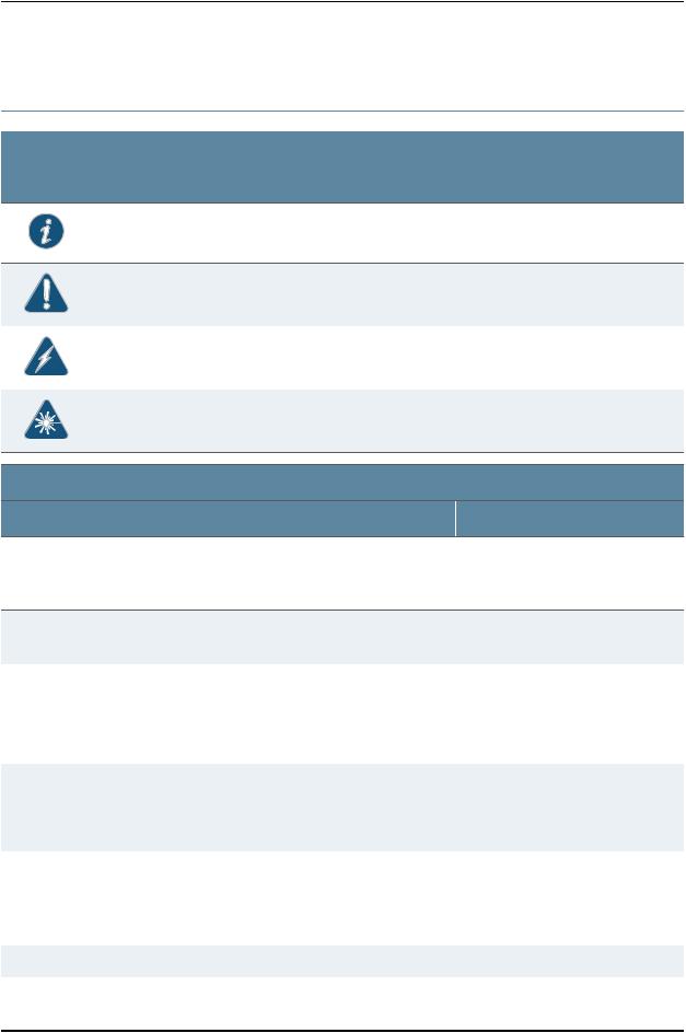
Documentation Symbols Key
Notice Icons |
|
|
Icon |
Meaning |
Description |
|
Informational note |
Indicates important features or instructions. |
|
Caution |
Indicates a situation that might result in loss of data or hardware |
|
|
damage. |
|
Warning |
Alerts you to the risk of personal injury or death. |
|
Laser warning |
Alerts you to the risk of personal injury from a laser. |
Text and Syntax Conventions |
|
|
Convention |
Description |
|
Bold text like this |
Represents text that you type. |
|
Fixed-width text like this |
Represents output that appears on the |
|
|
terminal screen. |
|
Italic text like this |
• Introduces important new terms. |
|
|
• |
Identifies book names. |
|
• |
IdentifiesRFCandInternetdrafttitles. |
Italic text like this |
Represents variables (options for which |
|
|
you substitute a value) in commands or |
|
|
configuration statements. |
|
Examples
To enter configuration mode, type the configure command:
user@host> configure
user@host> show chassis alarms
No alarms currently active
•Apolicytermisanamedstructurethat definesmatchconditionsandactions.
•Junos OS System Basics Configuration Guide
•RFC 1997, BGP Communities Attribute
Configure the machine’s domain name:
[edit]
root@# set system domain-name domain-name
Plain text like this |
Represents names of configuration |
|
statements, commands, files, and |
|
directories; IP addresses; configuration |
|
hierarchy levels; or labels on routing |
|
platform components. |
•To configure a stub area, include the stub statement at the [edit protocols ospf area area-id] hierarchy level.
•The console port is labeled CONSOLE.
< > (angle brackets) |
Enclose optional keywords or variables. |
stub <default-metric metric>; |
xviii |
Copyright © 2010, Juniper Networks, Inc. |

About This Topic Collection
Text and Syntax Conventions |
|
|
Convention |
Description |
Examples |
| (pipe symbol) |
Indicatesachoicebetweenthemutually |
broadcast | multicast |
|
exclusivekeywordsorvariablesoneither |
|
|
side of the symbol. The set of choices is |
(string1 | string2 | string3) |
|
oftenenclosedinparenthesesforclarity. |
|
# (pound sign) |
Indicates a comment specified on the |
rsvp { # Required for dynamic MPLS only |
|
samelineastheconfigurationstatement |
|
|
to which it applies. |
|
[ ] (square brackets) |
Enclose a variable for which you can |
community name members [ |
|
substitute one or more values. |
community-ids ] |
Indention and braces ( { } ) |
Identify a level in the configuration |
[edit] |
|
hierarchy. |
routing-options { |
|
|
static { |
|
|
route default { |
|
|
nexthop address; |
|
|
retain; |
|
|
} |
|
|
} |
|
|
} |
; (semicolon) |
Identifies a leaf statement at a |
|
|
configuration hierarchy level. |
|
J-Web GUI Conventions |
|
|
Bold text like this |
Represents J-Web graphical user |
• IntheLogicalInterfacesbox,selectAll |
|
interface (GUI) items you click or select. |
Interfaces. |
|
|
• To cancel the configuration, click |
|
|
Cancel. |
> (bold right angle bracket) |
Separates levels in a hierarchy of J-Web |
In the configuration editor hierarchy, |
|
selections. |
select Protocols>Ospf. |
Documentation Feedback
We encourage you to provide feedback, comments, and suggestions so that we can improve the documentation. Send e-mail to techpubs-comments@juniper.net with the following:
•Document URL or title
•Page number if applicable
•Software version
•Your name and company
Copyright © 2010, Juniper Networks, Inc. |
xix |

Complete Hardware Guide for EX2200 Ethernet Switches
Requesting Technical Support
TechnicalproductsupportisavailablethroughtheJuniperNetworksTechnicalAssistance Center (JTAC). If you are a customer with an active J-Care or JNASC support contract, or are covered under warranty, and need post-sales technical support, you can access our tools and resources online or open a case with JTAC.
•JTAC policies—For a complete understanding of our JTAC procedures and policies, review the JTAC User Guide located at http://www.juniper.net/us/en/local/pdf/resource-guides/7100059-en.pdf .
•Product warranties—For product warranty information, visit http://www.juniper.net/support/warranty/ .
•JTAC hours of operation—The JTAC centers have resources available 24 hours a day, 7 days a week, 365 days a year.
Self-Help Online Tools and Resources
For quick and easy problem resolution, Juniper Networks has designed an online self-service portal called the Customer Support Center (CSC) that provides you with the following features:
•Find CSC offerings: http://www.juniper.net/customers/support/
•Search for known bugs: http://www2.juniper.net/kb/
•Find product documentation: http://www.juniper.net/techpubs/
•Find solutions and answer questions using our Knowledge Base: http://kb.juniper.net/
•Download the latest versions of software and review release notes: http://www.juniper.net/customers/csc/software/
•Search technical bulletins for relevant hardware and software notifications: https://www.juniper.net/alerts/
•Join and participate in the Juniper Networks Community Forum: http://www.juniper.net/company/communities/
•Open a case online in the CSC Case Management tool: http://www.juniper.net/cm/
Toverifyserviceentitlementbyproductserialnumber,useourSerialNumberEntitlement (SNE) Tool: https://tools.juniper.net/SerialNumberEntitlementSearch/
Opening a Case with JTAC
You can open a case with JTAC on the Web or by telephone.
•Use the Case Management tool in the CSC at http://www.juniper.net/cm/ .
•Call 1-888-314-JTAC (1-888-314-5822 toll-free in the USA, Canada, and Mexico).
For international or direct-dial options in countries without toll-free numbers, see
http://www.juniper.net/support/requesting-support.html .
xx |
Copyright © 2010, Juniper Networks, Inc. |
PART 1
Switch and Components Overview and
Specifications
•EX2200 Switch Overview on page 3
•Component Descriptions on page 11
•Component Specifications on page 19
Copyright © 2010, Juniper Networks, Inc. |
1 |

Complete Hardware Guide for EX2200 Ethernet Switches
2 |
Copyright © 2010, Juniper Networks, Inc. |

CHAPTER 1
EX2200 Switch Overview
•EX2200 Switches Hardware Overview on page 3
•EX2200 Switch Models on page 4
•Chassis Physical Specifications for EX2200 Switches on page 5
•Front Panel of an EX2200 Switch on page 5
•Rear Panel of an EX2200 Switch on page 6
•EX2200 Switch Hardware and CLI Terminology Mapping on page 7
EX2200 Switches Hardware Overview
Juniper Networks EX Series Ethernet Switches provide scalable connectivity for the enterprise market, including branch offices, campus locations, and data centers. The switches run under the Juniper Networks Junos operating system (Junos OS), which provides Layer 2 and Layer 3 switching, routing, and security services. The same Junos OS code base that runs on EX Series switches also runs on all Juniper Networks J Series, M Series, MX Series, and T Series routers.
•EX2200 Switches on page 3
•Uplink Ports on page 3
•Power over Ethernet (PoE) Ports on page 4
EX2200 Switches
Juniper Networks EX2200 Ethernet switches provide connectivity for low-density environments.
EX2200 switches are available in models with either 24 or 48 built-in network ports and four uplink ports, with Power over Ethernet (PoE) either available in all built-in network ports or not available in any built-in network port. All models provide network ports that have 10/100/1000Base-T Gigabit Ethernet connectors and four uplink ports. These switches run under Junos OS for EX Series switches.
Uplink Ports
Each EX2200 switch has four uplink ports that support 1-gigabit small form-factor pluggable (SFP) transceivers for use with fiber connections and copper connections. See “Optical Interface Support in EX2200 Switches” on page 22.
Copyright © 2010, Juniper Networks, Inc. |
3 |

Complete Hardware Guide for EX2200 Ethernet Switches
Power over Ethernet (PoE) Ports
PoEportsprovideelectricalcurrenttodevicesthroughthenetworkcablessothatseparate power cords for devices such as IP phones, wireless access points, and security cameras are unnecessary. EX2200 switches are available with full (all 24 or 48 built-in network ports) or no PoE capability. Full PoE models are primarily used in IP telephony environments.
EX2200 switches running Junos OS Release 10.3 or later can supply up to 30 W to individual PoE ports, supporting powered devices that comply with IEEE 802.3af (PoE) and IEEE 802.3at (PoE+).
NOTE: IEEE 802.3at class 4 powered devices require category 5 or higher
Ethernet cables.
EX2200 switches running Junos OS Release 10.2 or earlier can supply up to 15.4 W to individual PoE ports, supporting powered devices that comply with IEEE 802.3af (PoE).
Related • EX2200 Switch Models on page 4
Documentation • Site Preparation Checklist for EX2200 Switches on page 33
EX2200 Switch Models
The EX2200 switch is available with 24 or 48 built-in network ports with full (all 24 or 48 built-in network ports) or no Power over Ethernet (PoE) capability. Table 1 on page 4 lists the EX2200 switch models.
Table 1: EX2200 Switch Models
|
|
|
Maximum PoE Power |
Model |
Access Ports |
Ports in Which PoE Is Available |
Available |
EX2200-24T-4G |
24 Gigabit Ethernet |
– |
– |
EX2200-24P-4G |
24 Gigabit Ethernet |
All 24 ports |
405 W |
EX2200-48T-4G |
48 Gigabit Ethernet |
– |
– |
EX2200-48P-4G |
48 Gigabit Ethernet |
All 48 ports |
405 W |
Related • Front Panel of an EX2200 Switch on page 5
Documentation • EX2200 Switches Hardware Overview on page 3
4 |
Copyright © 2010, Juniper Networks, Inc. |

Chapter 1: EX2200 Switch Overview
Chassis Physical Specifications for EX2200 Switches
The EX2200 switch chassis is a rigid sheet-metal structure that houses the hardware components. Table 2 on page 5 summarizes the physical specifications of the EX2200 switch chassis.
Table 2: Physical Specifications of the EX2200 Switch Chassis
Description |
Value |
Chassis height |
1.75 in. (4.45 cm) |
Chassis width |
• 17.5 in. (44.5 cm) |
|
• 19 in. (48.2 cm) with mounting brackets attached |
Chassis depth |
10.5 in. (26.7 cm) |
Weight |
• EX2200-24T: 6 lb (2.7 kg) |
|
• EX2200-24P: 8 lb (3.6 kg) |
|
• EX2200-48T: 8 lb (3.6 kg) |
|
• EX2200-48P: 10 lb (4.5 kg) |
Related |
• Rack Requirements for EX2200 Switches on page 39 |
Documentation |
• Cabinet Requirements for EX2200 Switches on page 40 |
|
• Mounting an EX2200 Switch on page 53 |
|
• Installing and Connecting an EX2200 Switch on page 51 |
Front Panel of an EX2200 Switch
The front panel of an EX2200 switch consists of the following components:
•Network ports—depending on the switch model, either of:
•24or4810/100/1000Base-TGigabitEthernetports,withPoweroverEthernet(PoE) not available in EX2200-24T and EX2200-48T
•24or4810/100/1000Base-TGigabitEthernetports,withPoweroverEthernet(PoE) available in EX2200-24P and EX2200-48P
•4 built-in SFP uplink ports
•2 chassis status LEDs
•4 port status mode LEDs
•Mode button
Figure 1 on page 6 shows the front panel of an EX2200 switch with 48 Gigabit Ethernet ports. Figure 2 on page 6 shows the front panel of an EX2200 switch with 24 Gigabit Ethernet ports.
Copyright © 2010, Juniper Networks, Inc. |
5 |

Complete Hardware Guide for EX2200 Ethernet Switches
Figure1:FrontPanelofanEX2200Switchwith48GigabitEthernetPorts
Chassis status LEDs
0 |
1 |
2 3 |
4 5 |
6 7 |
8 9 |
10 11 |
12 13 |
14 |
15 |
1617 |
1819 |
2021 |
22 23 |
2425 |
2627 |
2829 |
3031 |
3233 |
34 35 |
3637 |
3839 |
4041 |
4243 |
4445 |
46 47 |
|
|
SYS |
ALM |
0 |
1 |
2 |
3 |
 SPD
SPD
 DX Port status mode LEDs
EN
 POE
POE
|
|
|
|
|
Mode |
|
|
|
|
|
|
Network |
|
SFP |
button |
||
ports |
|
uplink |
|
||
|
|
|
ports |
|
|
g027000
Figure2:FrontPanelofanEX2200Switchwith24GigabitEthernetPorts
Chassis status LEDs
0 |
1 |
2 3 |
4 5 |
6 7 |
8 9 |
10 11 |
12 13 |
14 |
15 |
1617 |
1819 |
2021 |
22 23 |
|
|
SYS |
ALM |
0 |
1 |
2 |
3 |
 SPD
SPD
 DX Port status mode LEDs
EN
 POE
POE
|
|
|
|
|
Mode |
|
|
|
|
|
|
Network |
|
SFP |
button |
||
ports |
|
uplink |
|
||
|
|
|
ports |
|
|
g027002
Related |
• Chassis Status LEDs in EX2200 Switches on page 11 |
Documentation |
• Network Port and Uplink Port LEDs in EX2200 Switches on page 12 |
|
• Network Port Connector Pinout Information for an EX2200 Switch on page 20 |
|
• Rear Panel of an EX2200 Switch on page 6 |
|
• Installing a Transceiver in an EX Series Switch on page 65 |
|
• Removing a Transceiver from an EX Series Switch on page 95 |
|
• Installing and Connecting an EX2200 Switch on page 51 |
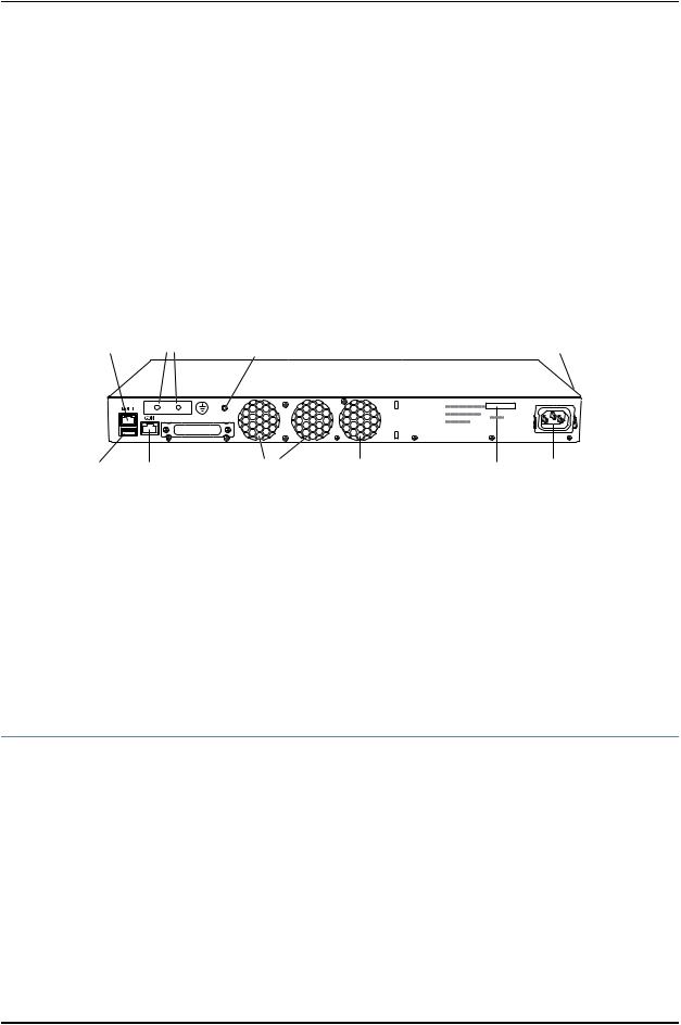
Rear Panel of an EX2200 Switch
The rear panel of the EX2200 switch consists of the following components:
•Management Ethernet port
•USB port
•Console port
•Protective earthing terminal
•ESD point
•Air exhaust
6 |
Copyright © 2010, Juniper Networks, Inc. |
Chapter 1: EX2200 Switch Overview
•Serial number ID label
•AC power cord inlet
Figure 3 on page 7 shows the rear panel of an EX2200 switch.
All EX2200 switches have three exhaust openings on the rear panel. The two leftmost exhaust openings have fans behind them and are open. The rightmost exhaust opening is open on Power over Ethernet (PoE) models and closed on non-PoE models. On PoE models, this opening exhausts the air from the fan at the air intake for the power supply on the side panel.
The power cord retainer clips extend out of the chassis by 3 in.
Figure 3: Rear Panel of an EX2200 Switch
Management |
Protective |
ESD |
Air intake with fan for power supply |
Ethernet port |
earthing terminal |
point |
(fan on PoE models only) |
EX2200-24-4G REV: X1 |
|
750-026464 REV: X3 |
Mfg. Date |
|
20090227 |
MAC: 00:23:9C:oE:19:00 |
|
|
MADE IN CHINA |
g027001
USB |
Console |
Air exhaust |
Air exhaust without fan |
Serial number |
AC power |
port |
port |
with fan |
(closed on non-PoE models) |
ID label |
cord inlet |
Related • Front Panel of an EX2200 Switch on page 5
Documentation • USB Port Specifications for an EX Series Switch on page 19
•Cooling System and Airflow in an EX2200 Switch on page 15
•Power Supply in EX2200 Switches on page 14
•Prevention of Electrostatic Discharge Damage on EX Series Switches on page 142
•Connecting Earth Ground to an EX Series Switch on page 67
•Installing and Connecting an EX2200 Switch on page 51
EX2200 Switch Hardware and CLI Terminology Mapping
This topic describes the hardware terms used in EX2200 switch documentation and the corresponding terms used in the Junos OS command line interface (CLI). See Table 3 on page 8.
Copyright © 2010, Juniper Networks, Inc. |
7 |

Complete Hardware Guide for EX2200 Ethernet Switches
Table 3: CLI Equivalents of Terms Used in Documentation for EX2200 Switches
|
|
|
Item in |
Additional |
Hardware Item (CLI) |
Description (CLI) |
Value (CLI) |
Documentation |
Information |
Chassis |
One of the following: |
– |
Switch chassis |
“Chassis Physical |
|
|
|
|
Specifications for |
|
• EX2200-24T-4G |
|
|
EX2200 Switches” on |
|
• EX2200-24P-4G |
|
|
page 5 |
|
• EX2200-48T-4G |
|
|
|
|
• EX2200-48P-4G |
|
|
|
FPC (n) |
Abbreviated name of |
Value of n is always 0. |
The switch does not |
Understanding |
|
the Flexible PIC |
|
have actual FPCs. In |
Interface Naming |
|
Concentrator (FPC) |
|
this case, FPC refers to |
Conventions on EX |
|
|
|
the switch itself. |
Series Switches |
|
One of the following: |
|
|
|
|
• EX2200-24T-4G |
|
|
|
|
• EX2200-24P-4G |
|
|
|
|
• EX2200-48T-4G |
|
|
|
|
• EX2200-48P-4G |
|
|
|
PIC (n) |
Abbreviated name of |
nisavalueintherange |
The switch does not |
Understanding |
|
the Physical Interface |
of 0-1. |
have actual PIC |
Interface Naming |
|
Card (PIC) |
|
devices; see entries for |
Conventions on EX |
|
|
|
PIC 0 through PIC 1 for |
Series Switches |
|
|
|
the equivalent item on |
|
|
|
|
the switch. |
|
One of the following: |
PIC 0 |
•24x 10/100/1000 Base-T
•48x 10/100/1000 Base-T
4x GE SFP |
PIC 1 |
Built-in network ports |
“Front Panel of an |
on the front panel of |
EX2200 Switch” on |
the switch |
page 5 |
Built-in uplink ports on |
“Front Panel of an |
the front panel of the |
EX2200 Switch” on |
switch |
page 5 |
Xcvr (n) |
Abbreviated name of |
n is a value equivalent |
Optical transceivers |
“Optical Interface |
|
the transceiver |
to the number of the |
|
Support in EX2200 |
|
|
port in which the |
|
Switches” on page 22 |
|
|
transceiver is installed. |
|
|
Power supply (n) |
Built-in power supply |
Value of n is always 0. |
AC power supply |
“Power Supply in |
|
|
|
|
EX2200 Switches” on |
|
|
|
|
page 14 |
Fan tray |
Fan tray |
– |
Fan tray |
“Cooling System and |
|
|
|
|
Airflow in an EX2200 |
|
|
|
|
Switch” on page 15 |
8 |
Copyright © 2010, Juniper Networks, Inc. |

Chapter 1: EX2200 Switch Overview
Related • EX Series Switches Hardware and CLI Terminology Mapping
Documentation • EX2200 Switches Hardware Overview on page 3
Copyright © 2010, Juniper Networks, Inc. |
9 |

Complete Hardware Guide for EX2200 Ethernet Switches
10 |
Copyright © 2010, Juniper Networks, Inc. |
Loading...