


 Loading...
Surface Water Pro
OPERATOR’S MANUAL
Surface Water Pro
OMPFP11362 ISSUE F1 (ENGLISH)
CALIFORNIA
Proposition 65 Warning
Diesel engine exhaust and some of its constituents are known to the State of California to cause cancer, birth defects, and other reproductive harm.
If this product contains a gasoline engine:
 WARNING
The engine exhaust from this product contains chemicals known to the State of California to cause cancer, birth defects or other reproductive harm.
The State of California requires the above two warnings.
Additional Proposition 65 Warnings can be found in this manual.
John Deere Ag Management Solutions
North American Edition
DCY
OMPFP11362
LITHO IN U.S.A.

Introduction
Foreword
WELCOME TO GREENSTAR™ system offered by John |
Accurately record all the numbers to help in tracing |
|
Deere. |
the components should it be stolen. Your dealer also |
|
READ THIS MANUAL carefully to learn how to operate |
needs these numbers when you order parts. File the |
|
identification numbers in a secure place off the machine. |
||
and service your system correctly. Failure to do so could |
||
result in personal injury or equipment damage. This |
WARRANTY is provided as part of John Deere’s support |
|
manual and safety signs on your machine may also be |
program for customers who operate and maintain their |
|
available in other languages. (See your John Deere |
equipment as described in this manual. The warranty is |
|
dealer to order.) |
explained on the warranty certificate which you should |
|
THIS MANUAL SHOULD BE CONSIDERED a permanent |
have received from your dealer. |
|
part of your system and should remain with the system |
This warranty provides you the assurance that John |
|
when you sell it. |
Deere will back its products where defects appear within |
|
MEASUREMENTS in this manual are given in both |
the warranty period. In some circumstances, John Deere |
|
also provides field improvements, often without charge |
||
metric and customary U.S. unit equivalents. Use only |
||
to the customer, even if the product is out of warranty. |
||
correct replacement parts and fasteners. Metric and inch |
||
Should the equipment be abused, or modified to change |
||
fasteners may require a specific metric or inch wrench. |
its performance beyond the original factory specifications, |
|
RIGHTHAND AND LEFTHAND sides are determined by |
the warranty will become void and field improvements |
|
facing in the direction of forward travel. |
may be denied. |
|
WRITE PRODUCT IDENTIFICATION NUMBERS (P.I.N.) |
|
|
in the Specification or Identification Numbers section. |
|
|
GREENSTAR is a trademark of Deere & Company |
|
|
|
OUO6050,0000AEC 1931JUL081/1 |
|
|
|
|
|
|
|
StellarSupport.Deere.com |
after the time of printing. For up to date information, |
|
NOTE: Product functionality may not be fully represented |
please visit StellarSupport.Deere.com. |
|
|
||
in this document due to product changes occurring |
|
|
|
OUO6050,0000FA5 1922OCT081/1 |
|
|
|
061611
PN=2

Contents
Page |
Page |
Safety
Recognize Safety Information ............................ |
051 |
Understand Signal Words................................... |
051 |
Follow Safety Instructions................................... |
051 |
Practice Safe Maintenance................................. |
052 |
Handle Electronic Components and |
|
Brackets Safely.............................................. |
052 |
Operate Guidance Systems Safely .................... |
053 |
Use Seat Belt Properly....................................... |
053 |
Theory of Operation
Theory of Operation............................................ |
101 |
Machine and Implement Setup
Setup.................................................................. |
151 |
Client, Farm, Field, and Task Setup ................... |
152 |
Machine Setup.................................................... |
153 |
Machine Offsets.................................................. |
155 |
Implement Setup ................................................ |
156 |
Implement Offsets .............................................. |
158 |
Machine GPS Receiver Setup.......................... |
1511 |
Implement GPS Receiver Setup....................... |
1512 |
Satellite Information
Satellite Information Softkey............................... |
201 |
Surface Water Pro Setup
Setup tab............................................................ |
251 |
Benchmark Settings ........................................... |
253 |
Creating a Benchmark Control Point.................. |
254 |
Calibrating to a Control Point.............................. |
254 |
Boundary and Tracking Setup
Record an External Boundary ............................ |
301 |
Survey
How to Survey a Field ........................................ |
351 |
Ditch
Setup Operation ................................................. |
401 |
Set Tracking Mode to Ditch Track ...................... |
403 |
Recorded Path for Ditching ................................ |
404 |
Record Ditch Track............................................. |
404 |
Modify Ditch Track.............................................. |
406 |
View Drain Profile............................................... |
407 |
Create Linear Drain Design................................ |
408 |
Create Best Fit Drain Design.............................. |
409 |
Cut or Clean Ditch Track .................................. |
4010 |
Levee
Set Operation to Levee....................................... |
451 |
Set to Levee Track ............................................. |
453 |
Mark Path (Drive Dial)........................................ |
454 |
Record a Levee Track ........................................ |
455 |
Set A B Lines.................................................... |
456 |
Pull Levee........................................................... |
456 |
Troubleshooting and Diagnostics
Diagnostic Readings........................................... |
501 |
Troubleshooting.................................................. |
503 |
Original Instructions. All information, illustrations and specifications in this manual are based on the latest information available at the time of publication.
The right is reserved to make changes at any time without notice.
COPYRIGHT © 2011
DEERE & COMPANY
Moline, Illinois
All rights reserved.
A John Deere ILLUSTRUCTION ® Manual
i
061611
PN=1

Contents
ii
061611
PN=2
Safety
Recognize Safety Information
This is a safetyalert symbol. When you see this symbol on your machine or in this manual, be alert to the potential for personal injury.
Follow recommended precautions and safe operating practices.
T81389 —UN—07DEC88
DX,ALERT 1929SEP981/1
Understand Signal Words
A signal word—DANGER, WARNING, or CAUTION—is used with the safetyalert symbol. DANGER identifies the most serious hazards.
DANGER or WARNING safety signs are located near specific hazards. General precautions are listed on CAUTION safety signs. CAUTION also calls attention to safety messages in this manual.
TS187 —19—30SEP88
DX,SIGNAL 1903MAR931/1
Follow Safety Instructions
Carefully read all safety messages in this manual and on your machine safety signs. Keep safety signs in good condition. Replace missing or damaged safety signs. Be sure new equipment components and repair parts include the current safety signs. Replacement safety signs are available from your John Deere dealer.
There can be additional safety information contained on parts and components sourced from suppliers that is not reproduced in this operator’s manual.
Learn how to operate the machine and how to use controls properly. Do not let anyone operate without instruction.
Keep your machine in proper working condition. Unauthorized modifications to the machine may impair the function and/or safety and affect machine life.
TS201 —UN—23AUG88
If you do not understand any part of this manual and need assistance, contact your John Deere dealer.
DX,READ 1916JUN091/1
051 |
PN=5 |
|
061611 |
Safety
Practice Safe Maintenance
Understand service procedure before doing work. Keep area clean and dry.
Never lubricate, service, or adjust machine while it is moving. Keep hands, feet , and clothing from powerdriven parts. Disengage all power and operate controls to relieve pressure. Lower equipment to the ground. Stop the engine. Remove the key. Allow machine to cool.
Securely support any machine elements that must be raised for service work.
Keep all parts in good condition and properly installed. Fix damage immediately. Replace worn or broken parts. Remove any buildup of grease, oil, or debris.
On selfpropelled equipment, disconnect battery ground cable () before making adjustments on electrical systems or welding on machine.
On towed implements, disconnect wiring harnesses from tractor before servicing electrical system components or welding on machine.
Handle Electronic Components and Brackets
Safely
Falling while installing or removing electronic components mounted on equipment can cause serious injury. Use a ladder or platform to easily reach each mounting location. Use sturdy and secure footholds and handholds. Do not install or remove components in wet or icy conditions.
If installing or servicing a RTK base station on a tower or other tall structure, use a certified climber.
If installing or servicing a global positioning receiver mast used on an implement, use proper lifting techniques and wear proper protective equipment. The mast is heavy and can be awkward to handle. Two people are required when mounting locations are not accessible from the ground or from a service platform.
TS218 —UN—23AUG88
DX,SERV 1917FEB991/1
TS249 —UN—23AUG88
DX,WW,RECEIVER 1924AUG101/1
052 |
PN=6 |
|
061611 |
Safety
Operate Guidance Systems Safely |
• Never get on or off a moving vehicle. |
||
Do not use guidance systems on roadways. Always turn |
• |
Verify the machine, implement, and guidance system |
|
are set up correctly. If using iTEC Pro, verify accurate |
|||
off (disable) guidance systems before entering a roadway. |
|
||
|
boundaries have been defined. |
||
Do not attempt to turn on (activate) a guidance system |
|
||
• Remain alert and pay attention to the surrounding |
|||
while transporting on a roadway. |
|
environment. |
|
Guidance systems are intended to aid the operator in |
• Take control of the steering wheel, when necessary, to |
||
performing field operations more efficiently. The operator |
|
avoid field hazards, bystanders, equipment, or other |
|
is always responsible for the machine path. |
|
obstacles. |
|
Guidance Systems include any application that automates |
• Stop operation if poor visibility conditions impair your |
||
|
ability to operate the machine or identify people or |
||
vehicle steering. This includes, but may not be limited to, |
|
obstacles in the machine path. |
|
AutoTrac, iGuide, iTEC Pro, ATU, and RowSense. |
• Consider field conditions, visibility, and vehicle |
||
To prevent injury to the operator and bystanders: |
|
configuration when selecting vehicle speed. |
|
|
|
||
|
|
JS56696,0000970 1910MAY111/1 |
|
|
|
|
|
|
|
|
|
Use Seat Belt Properly |
|
|
|
Use a seat belt when you operate with a rollover |
|
|
|
protective structure (ROPS) or cab to minimize chance of |
|
|
|
injury from an accident such as an overturn. |
|
|
|
Do not use a seat belt if operating without a ROPS or cab. |
|
—UN—23AUG88 |
|
Inspect seat belt and mounting hardware at least |
|
||
Replace entire seat belt if mounting hardware, buckle, |
|
|
|
belt, or retractor show signs of damage. |
|
|
|
once a year. Look for signs of loose hardware or belt |
|
TS205 |
|
damage, such as cuts, fraying, extreme or unusual wear, |
|
||
discoloration, or abrasion. Replace only with replacement parts approved for your machine. See your John Deere dealer.
DX,ROPS1 1929OCT071/1
053 |
PN=7 |
|
061611 |

Theory of Operation
Theory of Operation
Surface Water Pro is a two modular program—basic and advanced. Surface Water Pro (basic program) is designed for users to create levees and develop basic ditches
in their fields. Surface Water Pro Plus is an advanced ditching program that generates a “best fit drain”. Surface Water Pro Plus calculates the most effective drain in a field while moving the least amount of soil. This information is generated from vertical GPS signals calculated from StarFire 3000 or StarFire iTC receivers. Surface Water Pro Plus requires both a machine and implement receiver and cannot operate with just an implement receiver. Levee applications require John Deere RTK, and ditching requires either SF2 or RTK signal. For greater accuracy, we highly recommend the RTK solution.
NOTE: For best accuracy, recalibrate benchmark after power cycling the quick survey and absolute base station. When starting up the base station, the point of reference could shift slightly, so for the highaccuracy user, consider recalibrating.
Operating with an absolute survey base station reduces the need for benchmarking. In quick survey mode, anytime the base is moved or power is cycled, another calibration is required for high accuracy users.
John Deere implement mounts must be used because they reduce vibration and minimize hardware failures. Vibration mounts help minimize hardware failures over time, especially in ditching applications.
Record ditches from HIGH TO LOW elevation. Cut ditches in either direction.
To ensure highest system accuracy, do not operate Surface Water Pro and Pro Plus outside a ONE MILE radius of the Base Station.
Surface Water Pro features available on the GS3 display and our Apex Desktop Software provide value by offering ways to manage your topographic data better and ensure optimum water distribution for crop production. Apex Surface Water Pro features allow you to unload your GS3 survey data to generate Depression, Flow Direction, and Drainage maps utilizing GSDNet. You can also manage your Ditch and Levee Tracks from year to year by editing cut, slope, or drop of fall. Additionally, layering your ditch or levee tracks over your yield data displays your results from the work you completed. See your local John Deere Dealer or visit our website www.StellarSupport.com to learn more about these additional features for your Surface Water Pro program.
Reprogram receivers (Surface Water Pro Plus) at the vehicle receiver location. Each receiver must be updated individually every time a software update is available [3.20D or older]. You cannot have both receivers attached to the wiring harness when reprogramming.
IMPORTANT: A StarFire iTC receiver, or newer, is required for Surface Water Pro.
Surface Water Pro Plus does not support an Implement Receiver Only configuration. Do not run ditching with an implement receiver only—both a Machine & Implement receiver must be used to operate that software.
Surface Water Pro and Pro Plus Survey function is NOT compatible with Swath Control Pro. Do not use the survey function in conjunction with Swath Control Pro.
Surface Water Pro and Pro Plus is NOT compatible with iGuide Do not use in conjunction with iGuide.
JS56696,00009F3 1901JUN111/1
101 |
PN=8 |
|
061611 |
Machine and Implement Setup
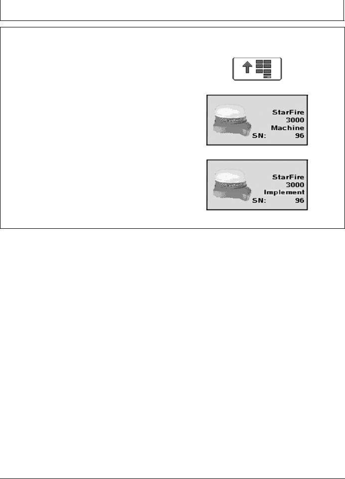
Setup
Machine must be GreenStar Ready. |
PC8663 —UN—05AUG05 |
|
|
To run Surface Water Pro, operator needs: |
|
• GreenStar Ready Machine |
|
• Constant Power |
MENU Softkey |
• Front Extension Harness (3 m or 10 m) |
PC12601 —UN—10MAY10 |
|
|
• Implement Application |
|
• Implement Receiver (if using Surface Water Pro Plus) |
|
To make Surface Water Pro function, set up for the |
|
following: |
|
• Machine |
|
• Machine GPS receiver |
|
• Implement (Optional for some functions) |
StarFire 3000 Machine Softkey |
• Implement GPS receiver (Optional) |
PC13595 —UN—11MAY11 |
• Guidance (Optional) |
|
• Implement Harness (Optional) |
|
Turn GS3 system on after connecting all hardware |
|
components. |
|
Receivers are used on both the machine and implement |
|
for some ditching applications. If two receivers are used, |
|
verify both StarFire 3000 receiver softkeys (Machine and |
StarFire 3000 Implement Softkey |
Implement) are shown on the display. |
JS56696,00009D1 1919MAY111/1 |
|
151 |
PN=9 |
|
061611 |
Machine and Implement Setup
Client, Farm, Field, and Task Setup
This is a required step for boundaries to run survey mode or to record ditch and levee tracks.
Select MENU softkey >> GREENSTAR 3 PRO softkey >> RESOURCES/CONDITIONS softkey >> RESOURCES tab.
The documentation screen allows the setup of operations and specific details associated with those operations.
IMPORTANT: When setting up the display with vehicle key in the accessory position (power on, engine off), turn key to OFF position for 20 seconds BEFORE starting the vehicle. This ensures the setup data is saved to the USB flash drive before operating.
If the vehicle is running during setup and programming, turn off the vehicle with key in the OFF position and wait 30 seconds before restarting. This ensures all data is saved to the USB flash drive.
DO NOT turn the key to the start position directly from the accessory position. The reduction
in voltage during the starting phase could result in a loss of all setup data.
Choose the correct information from CLIENT, FARM, FIELD, and TASK dropdown box or input new information. Task is required only if Documentation is used. It is not needed to set or AutoTrac ditch or levee tracks. Always setting tasks is a good standard practice though.
PC8663 —UN—05AUG05
MENU softkey
PC12685 —UN—14JUL10
GREENSTAR 3 PRO softkey
PC8676 —UN—05AUG05
RESOURCES/CONDITIONS softkey
PC10857BV —UN—15JUL08
Resources tab
JS56696,00009D2 1919MAY111/1
152 |
PN=10 |
|
061611 |
Machine and Implement Setup
Machine Setup |
PC8663 —UN—05AUG05 |
|
|
|
|
Machine and Implement Offsets are critical for Surface |
|
|
Water Pro to function. |
|
|
Select MENU softkey >> GREENSTAR 3 PRO softkey |
PC12685 —UN—14JUL10 |
MENU Softkey |
>> EQUIPMENT—allows access to MACHINE and |
|
|
|
|
|
IMPLEMENT setup screens. |
|
|
|
PC8677 —UN—05AUG05 |
GREENSTAR 3 PRO softkey |
|
|
|
|
|
EQUIPMENT Softkey |
|
PC10857BP —UN—15JUL08 |
|
|
|
MACHINE tab |
|
Continued on next page |
JS56696,00009D3 1901JUN111/3 |
|
|
|
153 |
PN=11 |
|
061611 |
Machine and Implement Setup
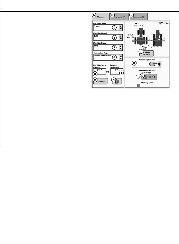
Machine Tab
NOTE: All items and changes will be saved under the current machine name.
Offsets are provided by some ISO implements and some John Deere tractors. Some list boxes may be grayed out when the machine is automatically recognized.
When setting up Surface Water Pro for the first time, creating a machine name for the vehicle is recommended. All dimensions and parameters set for this vehicle are used for Surface Water Pro operations.
The Machine and Implement tabs are required to be populated with equipment information such as:
•Type
•Model
•Name
•Offsets
Machine Type—Vehicle type being used (e.g. Tractor, Combine, Sprayer).
Machine Model—Model number of the vehicle being used. For John Deere vehicles, model numbers will be available from the drop down list.
Machine Name—The name is used to further clarify which machine is being used. For instance, if there are two 8430’s in your operation, the machine names may be “John” and “Deere”, or “84301” and “84302”, or simply “1” and “2”. However, settings associated to the tractor, such as turning radius, turn sensitivity, dimensions, etc., are stored to the name.
|
PC13768 —UN—17MAY11 |
Machine Tab |
|
A—Machine Tab |
H—Machine Turn Radius input |
B—Implement 1 Tab |
box |
C—Implement 2 Tab |
I— Turning Sensitivity input |
D—Machine Type dropdown |
box |
menu |
J—Change Offsets button |
E—Machine Model dropdown |
K—Recording Source |
menu |
dropdown menu |
F—Machine Name dropdown |
L—Record/Pause button |
menu |
M—COM Port button |
G—Connection Type |
N—Fuel button (Business Pack |
dropdown menu |
/ Europe Only) |
Continued on next page |
JS56696,00009D3 1901JUN112/3 |
154 |
PN=12 |
|
061611 |
Machine and Implement Setup
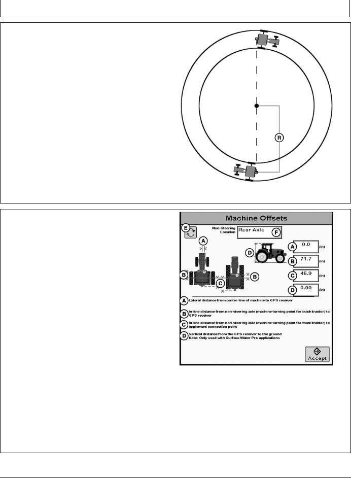
NOTE: Machine Turn Radius and Turning Sensitivity are for use with iTEC Pro only.
Machine Turn Radius—How sharp the machine can turn without an implement attached and without applying brake pressure. The turn radius is half the diameter as measured at the center of the rear axle of a row crop tractor, and the pivot point on tracks and 4WD tractors. Example: 8030 wheel tractors have a minimum turn radius of 6.1—6.7 m (20—22 ft). Choose a number to start with and change as needed for accuracy.
Turning Sensitivity—AutoTrac gain setting when the vehicle is in an automated turn. This is adjustable by the operator to improve performance (default 70).
Verify proper dimensions correspond to the Machine selected.
NOTE: Not all recording sources are available for all machines.
R—Machine Turn Radius
PC9890 —UN—05FEB07
Machine Turn Radius
JS56696,00009D3 1901JUN113/3
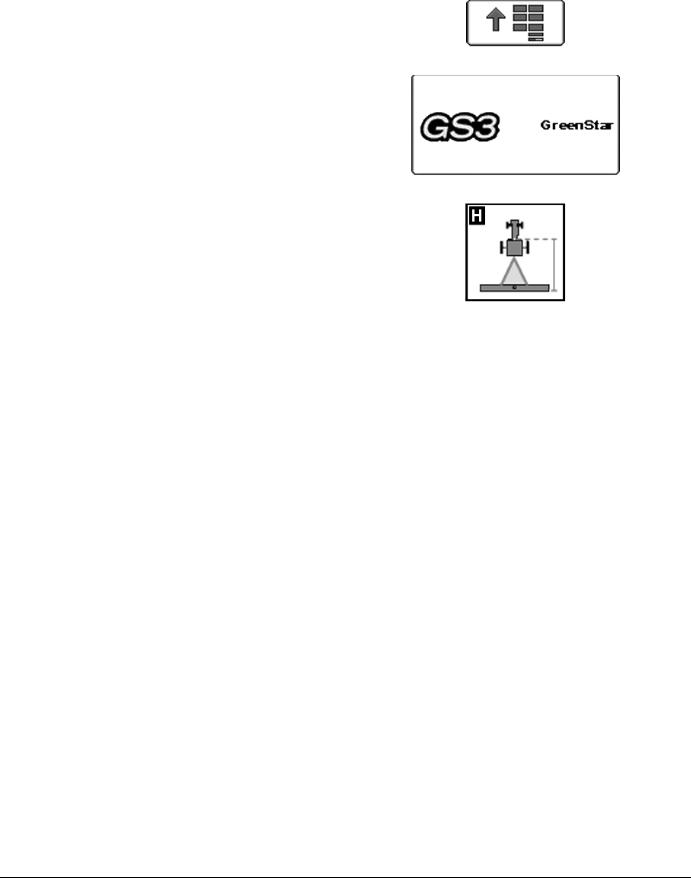
Machine Offsets
Select CHANGE OFFSETS button on Machine Setup screen.
Offsets are used to eliminate skips or overlaps due to an offset receiver.
To enter machine offsets:
•Select input box.
•Enter amount of offset in cm (in.) using numeric keypad and select enter button.
•Select the receiver toggle button to move the offset to the right or left of cab center.
If no receiver offset is required, RECEIVER OFFSET input box should read 0.
Machine offsets:
•A) Lateral Distance from centerline of machine to GPS receiver.
•B) Inline distance from nonsteering axle to GPS Receiver.
•C) Inline distance from nonsteering axle to connection point. The connection point is where the tractor connects to the implement (drawbar, hitch) except
on 2 pt pivoting implements (large planter). In this case, measure the distance back to the pivot point immediately behind the hitch.
•(D) Vertical distance from GPS receiver to the ground.
NOTE: Offset (D) is for use with Surface Water Pro.
|
PC13269 —UN—28APR11 |
Machine Offsets |
|
A—Lateral distance from |
D—Vertical distance from GPS |
centerline of machine to |
receiver to the ground |
GPS receiver |
E—Offset Toggle button |
B—Inline distance from |
F—NonSteering Axle Location |
nonsteering axle to GPS |
dropdown menu |
receiver |
|
C—Inline distance from |
|
nonsteering axle to |
|
connection point |
|
JS56696,00009D4 1911MAY111/1
155 |
PN=13 |
|
061611 |
|
Machine and Implement Setup |
|
|
|
|
|
|
|
Implement Setup |
PC8663 —UN—05AUG05 |
|
|
|
|
Implement 1 Tab |
|
|
Select MENU softkey >> GREENSTAR 3 PRO softkey >> |
MENU softkey |
|
EQUIPMENT tab >> IMPLEMENT tab. |
PC12685 —UN—14JUL10 |
|
|
|
|
|
PC8677 —UN—05AUG05 |
GREENSTAR 3 PRO softkey |
|
|
|
|
|
EQUIPMENT softkey |
|
Continued on next page |
JS56696,00009D5 1918MAY111/2 |
|
|
|
156 |
PN=14 |
|
061611 |
Machine and Implement Setup
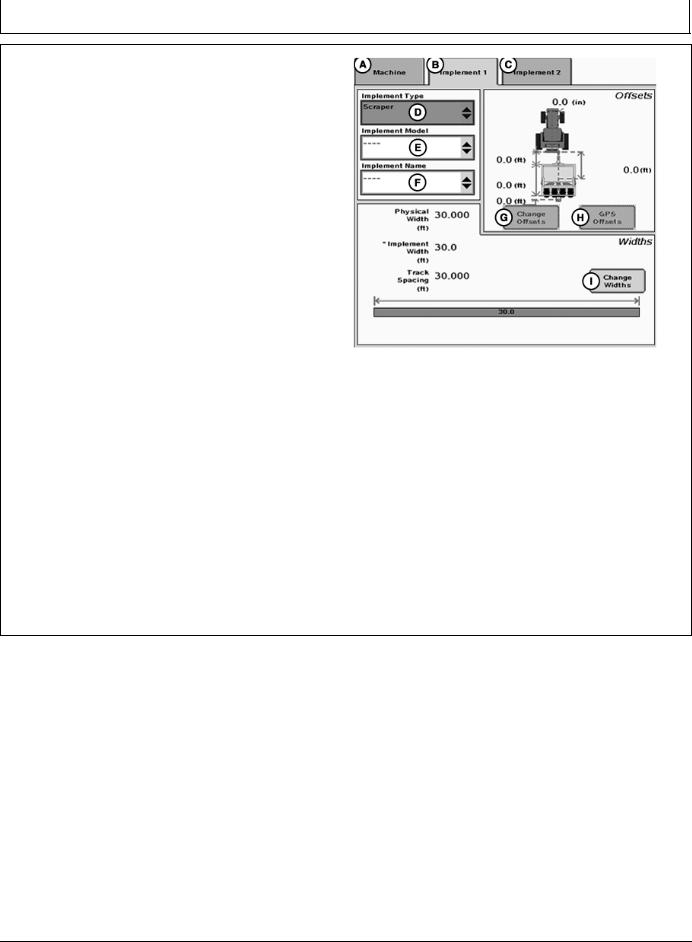
Select Change Offsets button (G).
NOTE: All items and changes will be saved under the current implement name. Implement name is also the base for transferring data to the desktop software (if supported).
Verify implement setup before operating Surface Water Pro Plus. Be sure hydraulic hookups are in the proper locations and no other changes to the implement have been made that could cause unexpected behavior or a change in vertical receiver position.
When using Surface Water Pro Plus for the first time, it is necessary to define a name for the implement being used. All dimensions and parameters including GPS offsets on the implement is stored to this name.
For implement setup, the following tabs are required to be populated:
•Implement Type
•Implement Model
•Implement Name—information is stored in relation to this name
Verify or Enter implement: Type, Model, and Name in dropdown boxes.
Implement name allows operator to save implement dimensions.
PC13799 —UN—02JUN11
Implement Tab
A—Machine tab |
F—Implement Name |
B—Implement 1 tab |
dropdown menu |
C—Implement 2 tab |
G—Change Offsets button |
D—Implement Type dropdown |
H—GPS Offsets button |
menu |
I— Change Widths button |
E—Implement Model |
|
dropdown menu |
|
NOTE: Select the correct name before changing any offset dimensions.
Implement Type is required to be selected. Implement Names are filtered by the type when Implement Model is selected. For example, scraper or rotary ditcher.
Select CHANGE OFFSET button (G) and proceed to following Implement Offsets section.
CHANGE WIDTHS button (I)—IMPLEMENT WIDTHS are used to calculate CUT VOLUME on the EDIT DRAIN screen. For example, Implement Width is entered as the cutting blade width for the scraper.
JS56696,00009D5 1918MAY112/2
157 |
PN=15 |
|
061611 |
Machine and Implement Setup
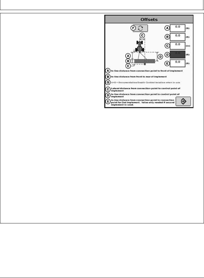
Implement Offsets
Select MENU softkey >> GREENSTAR 3 PRO softkey >> EQUIPMENT softkey >> IMPLEMENT tab >> CHANGE OFFSETS button.
IMPORTANT: Distance (D) is measured when the implement is in the FULLY RAISED position. This dimension is critical for accurate ditch designs.
Remember: Always measure to the same place on the receiver when measuring (that is, top, middle, and others).
Implement Offsets—Used to define the actual implement position relative to the tractor. This is important for ensuring the implement is lined up to the field at the end of turns and in determining where the implement is for the Minimize Skips and Minimize Overlaps feature (see Change Settings on Machine tab).
•A) Inline distance from connection point to front of implement. On pulltype implements, think of this as the tongue. For more precision, it is actually the dimension from the pinbolt to the front side of where the work gets done (front ranks of field cultivator, seed drop point on a planter).
•B) Working Length of the implement. On ground engagement tools, this is the distance from the front rank of sweeps or points to the rear rank. Refer to implement manufacturer’s Operator’s Manual for this value.
•C) Lateral distance from connection point to control point of implement. This is the lateral distance from the center of the tractor to the center of the implement which will be 0.0 for most common implements. This dimension is used to alert the operator to potential collisions. This is critical for proper endturn performance and may need to be adjusted.
•D) Inline distance from connection point to control point of implement. In many cases, this distance will be from the connection point to the carrying wheels. For proper turns, measure this distance with implement at the height it typically will be at while turning.
NOTE: These dimensions may need to be adjusted for finetuning performance in the field.
IMPORTANT: Ensure vertical distance (D) is measured from the GPS receiver to the ground when the implement is in the FULLY RAISED position.
PC11405 —UN—15OCT08
Implement Offsets
A—Inline distance from connection point to front of implement.
B—Inline distance from front to rear of implement.
C—Lateral distance from connection point to control point of implement.
D—Inline distance from connection point to control point of implement.
E—Inline distance from connection point to connection point for second implement. Value only needed if second implement is used.
F—Offset Toggle button G—A+B = Documentation / Swath Control location
when in use.
Remember: Always measure to the exact same place on the receiver when measuring (that is, top, middle, and others.).
NOTE: For a rotary ditcher, dimension (C) refers to the distance from the receiver to the cutting edge. On a rotary ditcher the cutting edge is the bottom of the paddle wheel, since this contacts the soil first. This dimension could be adjusted depending on individual requirements.
Continued on next page |
JS56696,00009D6 1911MAY111/4 |
158 |
PN=16 |
|
061611 |

Machine and Implement Setup
PC10376 —UN—13OCT07
Scraper Overhead
PC10375A —UN—14OCT07
Scraper Profile
A—Inline distance from connection pivot point to GPS receiver.
B—Lateral distance from implement center to GPS receiver.
C—Vertical distance from the GPS receiver to the cutting edge.
D—Vertical distance from the GPS receiver to the ground in the fully raised position.
E—Offset Toggle button F—Accept button
Continued on next page
PC10378A —UN—14OCT07
Rotary Ditcher Overhead
PC10377 —UN—13OCT07
Pull Type Rotary Ditcher Profile
PC13801 —UN—02JUN11
Implement GPS Offsets
JS56696,00009D6 1911MAY112/4
159 |
PN=17 |
|
061611 |
Machine and Implement Setup
|
PC9902 —UN—09JAN07 |
PC9903 —UN—09JAN07 |
|
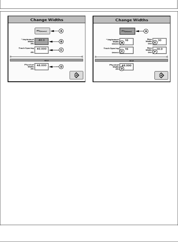
Track Spacing |
Track Spacing |
A—m (ft)/(rows) button |
C—Track Spacing |
E—Row Width |
B—Implement Width |
D—Physical Width |
|
Implement Widths—Used to enter implement width and track spacing for guidance. This value is also used to calculate total area when documenting the operation. Verify implement type, model, name, implement width and track spacing when changing implements. Implement width and track spacing are independent of each other.
NOTE: IMPLEMENT tab will show HEADER for Combines, ROW UNITS for Cotton Pickers, and BOOM for Sprayer.
Implement width may come from controller on select controllers such as SeedStar.
In some cases, a higher degree of precision can be achieved for track spacing when track spacing is entered in by rows instead of feet. More decimal places are used in the track spacing calculation when entered in by rows versus the three decimal places allowed when entered by feet.
Defining Implement Width and Track Spacing.
Implement width and track spacing can be defined two ways: enter the working width of the implement, or enter the number of rows and the row spacing. To toggle between these two, select the m (ft)/(rows) button.
•Implement Width m (ft)—enter total implement working width
•Implement Width rows—enter number of rows and the row spacing in inches
Track Spacing—Used in guidance for how far each pass is from the last pass. It is entered the same way as Implement Width. For “perfect” guess rows, this distance will be the same as Implement Width. To ensure some
overlap for tillage or spraying, or to account for some GPS drift, you may choose to make the Track Spacing somewhat less than the Implement Width.
Physical Width—The actual width of the entire implement when being used in the field when the implement is raised. It is sometimes larger than Implement Width.
Using a planter as an example, the marker arms and blades are wider than the working width. This width needs to be entered if markers are not used, or are used and completely folded on the ends. If markers are only partially folded during turns, enter this larger dimension.
IMPORTANT: Width measurements are used to help alert an operator of potential intersections between the implement and an impassable boundary. The operator still needs to be aware of potential collisions if there are times the implement is wider than the dimension entered (e.g. marker arm lowered). If markers are used in the field, add the width of both markers to give ultimate alarms of possible intersections.
NOTE: As a buffer to avoid obstacles, additional Physical Widthmaybeaddedtotheimplementtocompensate for several things, one of these being GPS drift.
Signal |
Approximate Physical Width |
|
added to Implement |
RTK |
0.6 m (2 ft) |
|
|
SF2 |
0.9 m (3 ft) |
|
|
SF1 |
3.4 m (11 ft) |
|
|
Physical Width Table
Continued on next page |
JS56696,00009D6 1911MAY113/4 |
1510 |
PN=18 |
|
061611 |
Loading...