


AC1-CG16H,
AC2-CG35H Compresserators
Operator’s Manual |
|

Introduction
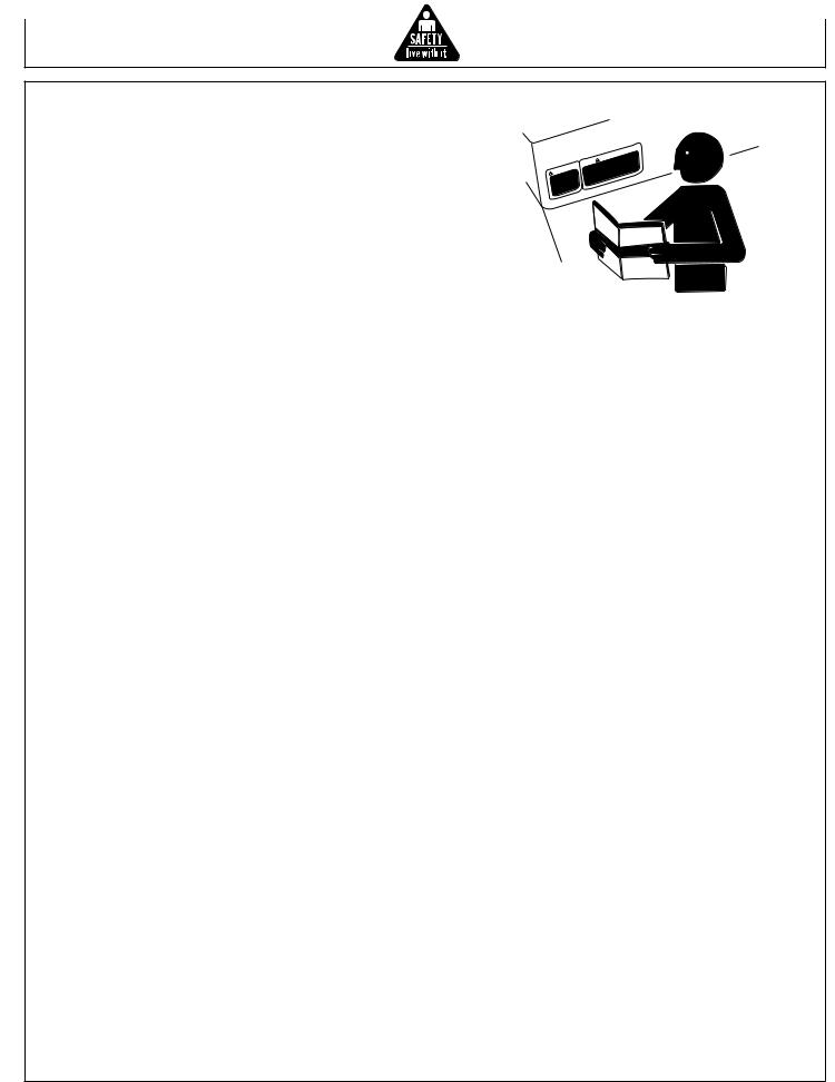
THANK YOU for purchasing a John Deere product.
READ THIS MANUAL carefully to learn how to operate and service your machine correctly. Failure to do so could result in personal injury or equipment damage. This manual and safety signs on your machine may also be available in other languages. (See your John Deere dealer to order.)
THIS MANUAL SHOULD BE CONSIDERED a permanent part of your machine and should remain with the machine when you sell it.
MEASUREMENTS in this manual are given in both metric and customary U.S. unit equivalents. Use only correct replacement parts and fasteners. Metric and inch fasteners may require a specific metric or inch wrench.
RIGHT HAND AND LEFT HAND sides are determined by facing the motor end of the machine.
The SERIAL NUMBER is located in the Specification or Identification Numbers section. Accurately record all the numbers to help in tracing the machine should it be stolen. Your dealer also needs these numbers when you order parts. File the identification numbers in a secure place off the machine.
WARRANTY is provided from your John Deere dealer for customers who operate and maintain their equipment as described in this manual. The warranty is explained on the warranty certificate shown in this manual.
This warranty provides you the assurance that your dealer will back products where defects appear within the warranty period. Should the equipment be abused, or modified to change its performance beyond the original factory specifications, the warranty will become void.
|
|
Operator’s Manual |
|
||
|

Contents
|
Page |
Safety ......................................................................... |
5 |
Safety Signs ............................................................ |
14 |
Controls .................................................................. |
15 |
Installation ............................................................... |
16 |
Operation ................................................................. |
20 |
Troubleshooting ..................................................... |
23 |
Maintenance ............................................................ |
25 |
Storage .................................................................... |
29 |
Specifications ......................................................... |
30 |
Warranty ................................................................... |
31 |
All information, illustrations and specifications in this manual are based on the latest information available at the time of publication. The right is reserved to make changes at any time without notice.
Operator’s Manual |
|

Contents
Operator’s Manual

Safety
Recognize safety information
This is the safety alert symbol. When you see this symbol on your machine or in this manual, be alert to the potential for personal injury.
Follow recommended precautions and safe operating practices.
understand signal words
A signal word--DANGER, WARNING or CAUTION--is used with the safety-alert symbol. DANGER identifies the most serious hazards.
DANGER or WARNING safety signs are located near specific hazards. General precautions are listed on CAUTION safety signs. CAUTION also calls attention to safety messages in this manual.
follow safety instructions
Carefully read all safety messages in this manual and safety signs on your machine. Keep safety signs in good condition. Replace missing or damaged safety signs. Be sure new equipment components and repair parts include the current safety signs. Replacement safety signs are available from your John Deere dealer.
Learn how to operate the machine and how to use controls properly. Do not let anyone operate without instruction.
Keep your machine in proper working condition.
Unauthorized modifications to the machine may impair the function and/or safety and affect machine life.
If you do not understand any part of this manual and need assistance, contact your John Deere dealer.
|
|
|
|
|
G |
|
|
|
|
|
IN |
|
|
|
|
|
N |
|
|
|
|
|
R |
|
|
|
|
A |
|
|
IN |
|
||
W |
|
|
GS |
|
||
|
|
|
S. |
|||
|
|
NIN |
|
|||
AR |
|
AL |
|
|||
W |
|
|
NU |
|
|
|
HEMA |
SIN |
. |
||||
T |
|
|
ING |
|
||
|
|
RN |
|
LS |
||
|
A |
|
UA |
|
||
W |
|
AN |
|
|
||
|
|
EM |
|
|
|
|
TH |
|
|
|
|
||
|
|
|
|
|
|
|
|
|
|
N |
|
|
|
|
|
|
|
|
|
|
U |
IO |
ON |
|
|
||||||
|
|
|
|
A |
|
T |
|
TI |
|
SIN |
|||||
|
|
|
|
|
|
|
|
|
|
|
S |
||||
|
|
|
C |
|
|
|
|
AU |
|
|
|
AL |
|||
|
|
|
|
|
|
|
|
OC |
|
|
NU |
|
|||
|
|
|
|
IN |
|
|
|
HE |
MA |
|
SIN |
||||
|
|
|
NS |
|
S |
|
|
|
UT |
|
|
|
LS |
||
|
|
TIO |
|
|
O |
CA |
|
|
|
UA |
|||||
AU |
|
AL |
|
|
|
|
|
AN |
|
||||||
OC |
|
|
NU |
|
|
|
|
|
|
EM |
|
|
|
||
HEMA NSIN |
|
OTH |
|
|
|
|
|
||||||||
OT |
|
TIO |
|
|
S |
|
|
|
|
|
|
|
|
|
|
|
AU |
|
|
AL |
|
|
|
|
|
|
|
|
|
||
OC |
|
NU |
|
|
|
|
|
|
|
|
|
|
|||
|
HE |
MA |
|
|
|
|
|
|
|
|
|
|
|
|
|
OT |
|
|
|
|
|
|
|
|
|
|
|
|
|
|
|
Operator’s Manual
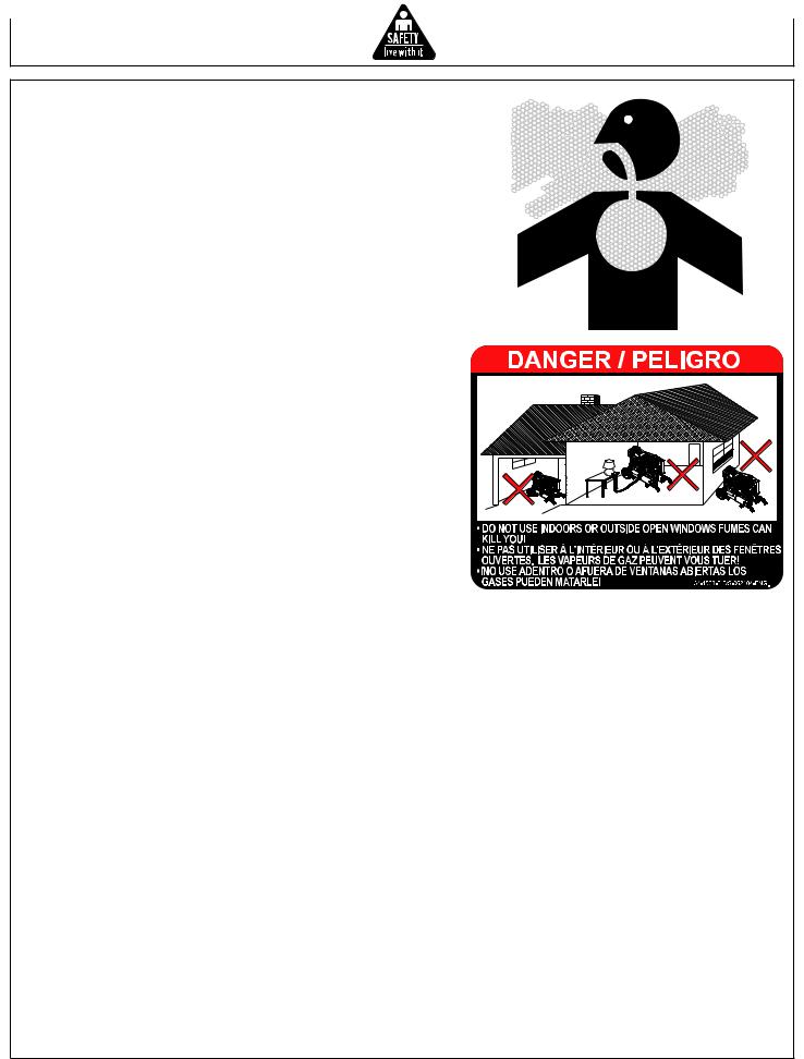
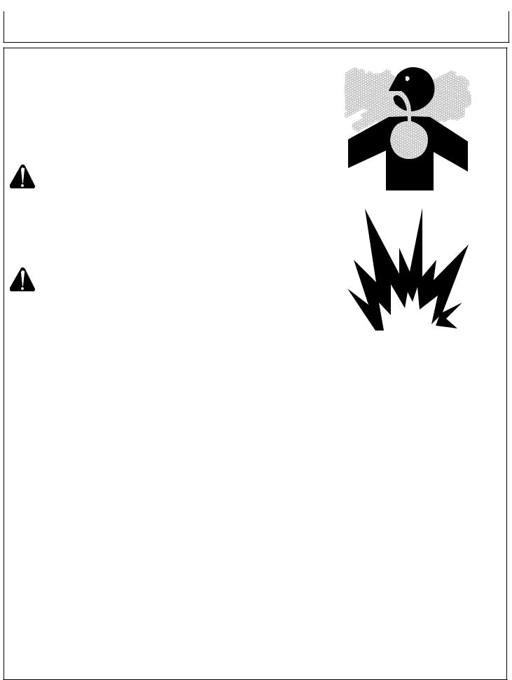
carbon monoxide - POISONOUS GAS
Use unit outdoors, away from open windows, vents, or doors.
Unit exhaust contains carbon monoxide - a poisonous gas that can kill you. You CAN NOT smell or see this gas.
Never use the unit in enclosed or partially-enclosed spaces. The unit can produce high levels of carbon monoxide very quickly. When you use this unit, remember that you cannot smell or see carbon monoxide. Even if you can’t smell exhaust fumes, you may still be exposed to carbon monoxide.
If you start to feel sick, dizzy, or weak while using the unit, get to fresh air RIGHTAWAY. DO NOT DELAY. The carbon monoxide from the unit can rapidly lead to full incapacitation and death.
If you experience serious symptoms, get medical attention immediately. Inform medical staff that carbon monoxide poisoning is suspected. If you experienced symptoms while indoors, have someone call the fire department to determine when it is safe to re-enter the building.
Never operate the unit in an explosive atmosphere, near combustible materials or where ventilation is not sufficient to carry away exhaust fumes. Exhaust fumes can cause serious injury or death.
NEVER use the unit indoors, including in homes, garages, basements, crawl spaces, and other enclosed or partially-enclosed areas, even with ventilation. Opening doors and windows or using fans will not prevent carbon monoxide build-up in the home.
Follow the instructions that come with your unit. Locate the unit outdoors and away from doors, windows, and vents that could allow the carbon monoxide gas to come indoors.
ONLY run unit outdoors and away from air intakes.
NEVER run unit inside homes, garages, sheds, or other semienclosed spaces. These spaces can trap poisonous gases EVEN IF you run a fan or open doors and windows.
If you start to feel sick, dizzy, or weak while using the unit, shut if off and get fresh air RIGHT AWAY. See a doctor. You may have carbon monoxide poisoning.
Install battery-operated carbon monoxide alarms or plug-in carbon monoxide alarms with battery back-up in your home, according to the manufacturer’s installation instructions. The carbon monoxide alarms should be certified to the requirements of the latest safety standards for carbon monoxide alarms. (UL 2034, IAS 6-96, or CSA 6.19.01).
Test your carbon monoxide alarm frequently and replace dead batteries.
Operator’s Manual
SAFETY WARNING WHEN REFUELING
Injury or death may occur as a result of improper fueling. Do not smoke while filling engine fuel tank.
Always refuel slowly to avoid the possibility of spilled fuel which may cause a risk of fire.
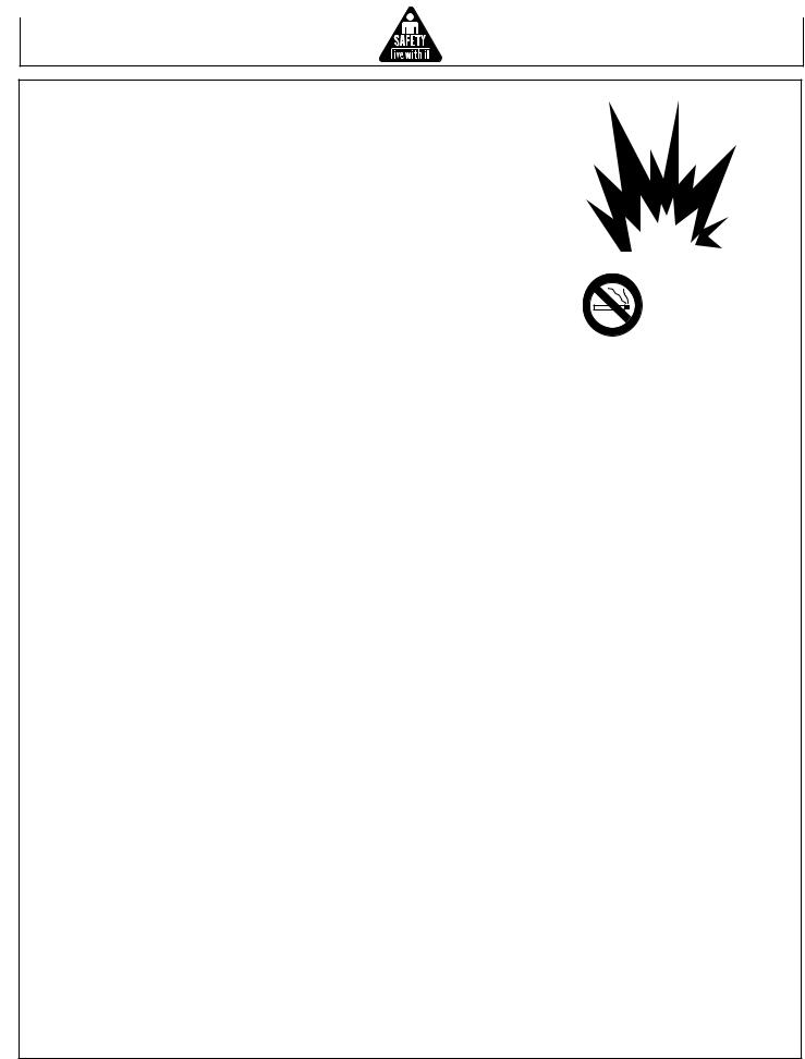
Gasoline is extremely flammable and its vapors can explode if ignited.
Observe all safety regulations for the safe handling of fuel. Handle fuel in safety containers. If the container does not have a spout, use a funnel.
Do not overfill the fuel tank, leave room for the fuel to expand.
Fill the tank only on an area of bare ground. While fueling the tank, keep heat, sparks and open flame away. Carefully clean up any spilled fuel before starting engine.
Always fill fuel tank in an area with plenty of ventilation to avoid inhaling dangerous fumes.
NEVER store fuel for your unit in the home. Gasoline, propane, kerosene, and other flammable liquids should be stored outside of living areas in properly-labeled, non-glass safety containers. Do not store them near a fuel-burning appliance, such as a natural gas water heater in a garage. If the fuel is spilled or the container is not sealed properly, invisible vapors from the fuel can travel along the ground and can be ignited by the appliance’s pilot light or by arcs from electric switches in the appliance.
Operator’s Manual |
|

ELECTRICAL HAZARDS
This product must be grounded. If it should malfunction or breakdown, grounding provides a path of least resistance for electric current to reduce the risk of electric shock.
DANGER - Improper connection of the equipmentgrounding conductor can result in a risk of electrocution. Check with a qualified electrician or service person if you are IN doubt as to whether the unit is properly grounded.
This unit is equipped with a grounding terminal for your protection. Always complete the ground path from the unit to an external ground source as instructed in the section labeled “Grounding Instructions” in the Preparation section of this manual.
The unit is a potential source of electrical shock if not kept dry. Keep the unit dry and do not use in rain or wet conditions. To protect from moisture, operate it on a dry surface under an open, canopy-like structure. Dry your hands if wet before touching the unit.
Plug appliances directly into the unit. Or, use a heavy duty, outdoorrated extension cord that is rated (in watts or amps) at least equal to the sum of the connected appliance loads. Check that the entire cord is free of cuts or tears and that the plug has all three prongs, especially a grounding pin.
NEVER try to power the house wiring by plugging the unit into a wall outlet, a practice known as “back feeding”. This is an extremely dangerous practice that presents an electrocution risk to utility workers and neighbors served by the same utility transformer. It also bypasses some of the built-in household circuit protection devices.
If you must connect the unit to the house wiring to power appliances, have a qualified electrician install the appropriate equipment in accordance with local electrical codes. Or, check with your utility company to see if it can install an appropriate power transfer switch.
For power outages, permanently installed stationary units are better suited for providing backup power to the home. Even a properly connected portable unit can become overloaded. This may result in overheating or stressing the unit components, possibly leading to a unit failure.
|
Operator’s Manual |

Risk of Fire or explosion
Serious injury or death may occur from normal sparks in the engine ignition system or engine exhaust/muffler. Always operate the unit in a well ventilated area free of flammable vapors, combustible dust, gases or other combustible materials.
DO NOT SMOKE if spraying flammable material. Locate the unit at least 20 feet away from the spray area. (An additional hose may be required.)
Never fill the engine fuel tank while the engine is running or hot. Allow the engine to cool two minutes before refueling. Do not refuel indoors or in a poorly ventilated area.
Do not operate the unit if gasoline is spilled. Wipe the unit clean and move it away from the spill. Avoid creating any ignition until the gasoline has evaporated.
Do not store the unit near an open flame or any equipment such as a stove, furnace, water heater, etc. which utilizes a pilot light or sparking device.
A spark arrester must be added to the muffler of this engine if it is to be used on any forest covered, brush covered or grass covered unimproved land. The arrester must be maintained in effective working order by the operator.
Serious injury may occur if any of the unit's ventilation openings are restricted, causing the unit to overheat and start a fire. Never place objects against or on top of the unit. Operate the unit at least 12 inches away from any wall or obstruction that would restrict proper ventilation.
Risk of Bursting
Serious injury or death may occur from an air tank explosion if air tanks are not properly maintained. Drain air tank daily or after each use to prevent moisture buildup in the air tank.
If air tank develops a leak, replace the air tank immediately. Never repair, weld or make modifications to the air tank or its attachments. Use only genuine manufacturer repair parts for your unit. Never make adjustments to the factory set pressures.
Serious injury may occur from the unit malfunction or exploding accessories if incorrect system components, attachments or accessories are used. Never exceed manufacturers maximum allowable pressure rating of attachments.
Because of extreme heat, do not use plastic pipe or lead tin soldered joints for a discharge line.
Never use the unit to inflate small, low pressure objects such as toys.
Operator’s Manual
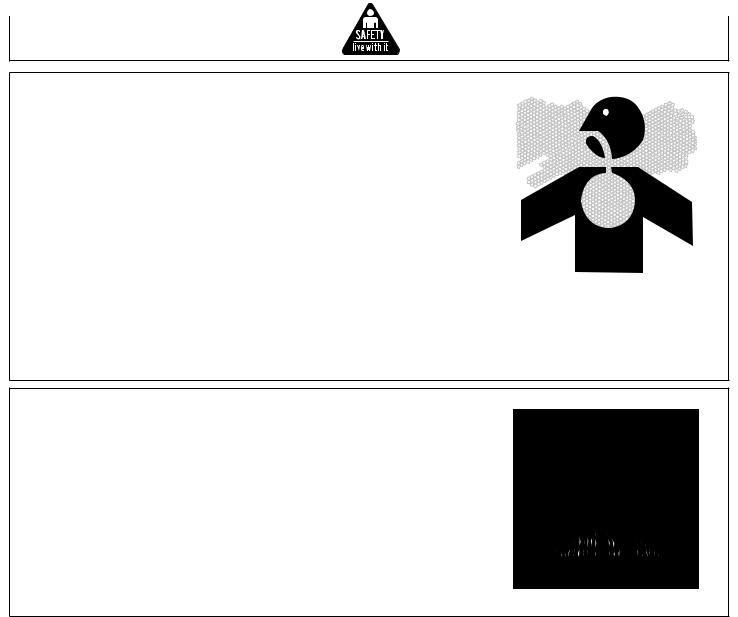
Risk of Breathing
Serious injury or death could occur from inhaling compressed air. The air stream may contain carbon monoxide, toxic vapors or solid particles. Never inhale air from the unit either directly or from a breathing device connected to the unit.
Serious injury or death may occur from inhaling engine exhaust. This unit was designed for outdoor use. Never operate this unit in an enclosed area. Always make certain there is adequate ventilation (fresh outside air) for breathing and combustion. This will prevent the buildup of dangerous carbon monoxide gases. Beware of poorly ventilated areas, or areas with inadequate exhaust fans.
Sprayed materials such as paint, solvents, paint remover, insecticides, weed killers, etc. contain harmful vapors and poisons. Operate the unit only in a well ventilated area. Follow all safety instructions provided with the materials you are spraying. Use of a respirator may be required when working with some materials.
Risk of Burns
Serious injury could occur from touching exposed metal parts. These areas can remain hot for some time after the unit is shutdown. Never allow any part of your body or other materials to make contact with any exposed metal parts on the unit.
Never allow any part of your body to contact the engine muffler, compressor head or adjacent areas.
10 |
Operator’s Manual |
Risk of Flying Objects
Soft tissue damage can occur from the compressed air stream. Always wear safety glasses to shield the eyes from flying debris.
Never point the air stream at any part of your body, anyone else or animals.
Never leave pressurized air in the unit. Shut off the unit and relieve pressure when storing or attempting maintenance.
Serious injury can occur from loose debris being propelled at a high speed from the compressed air stream. Always maintain a safe distance from people and animals while operating the unit.
Do not move the unit while air tank is under pressure. Do not attempt to move the unit by pulling on the hose.
Risk from Moving Parts
Risk of bodily injury from moving parts. Before performing maintenance, always turn off the unit. Bleed pressure from the air hose and disconnect spark plug wire to prevent engine from starting unexpectedly. All repairs to the unit should be made by an Authorized Service person.
Do not operate without protective covers/guards. Always turn off the unit before removing any guard. Replace damaged covers/guards before using the unit.
|
|
|
|
|
Operator’s Manual |
11 |
|||
important safety instructions
WARNING: To reduce the risk of injury, read this operator’s manual completely before using. When using this product, the following basic precautions should always be followed:
1.Risk from Negligence: Risk of injury from negligent use. Never allow children or adolescents to operate this unit! Stay alertwatch what you are doing. Do not operate the unit when fatigued or under the influence of alcohol or drugs. Know how to stop the unit. Be thoroughly familiar with controls.
2.Risk of Unit Damage: Risk of major repair. Do not operate the unit without an air filter. Do not operate the unit in a corrosive environment. Always operate the unit in a stable, secure position to prevent the unit from falling. Follow all maintenance instructions listed in this manual.
3.When starting the unit, using recoil starter grip, be sure that nothing is in a position to be hit by the operator’s hand or arm. Be sure the switch on electric power tools is in the “OFF” position before plugging them into the unit.
4.Do not operate the unit or any electrical tool in any area where water or similar materials constitute an electrical hazard to the operator. Do not operate on wet surfaces, in rain or in snow.
5.Always be sure that the unit is on secure footing so that it cannot slide or shift around, endangering workers.
6.Avoid contacting the hot exhaust manifold, muffler or cylinder(s).
7.Keep clear of all rotating parts.
8.Unless the tool or appliance is double insulated, it must be grounded through a properly grounded receptacle. Tools and appliances which have 3 prong plugs must be plugged into extension cords and electrical receptacles with 3 holes. Before operating any electrical item, be sure it is in good repair.
9.Beware of using this equipment in confined spaces. Confined spaces, without sufficient fresh air ventilation, can contain dangerous gases. Running gasoline engines in such environments can lead to deadly explosions and/or asphyxiation.
10.Use extreme caution when lifting this unit. This unit is heavy so proper lifting techniques should be used.
SAVE THESE INSTRUCTIONS
|
|
|
|
|
|
|
|
|
|
N |
|
|
|
|
|
|
|
|
|
IO |
|
IN |
|
|
|
|
|
|
|
|
UT |
|
|||
|
|
|
|
|
|
A |
|
|
|
S |
|
|
|
|
|
|
C |
|
|
CAUTIONSAL |
|||
|
|
|
|
|
|
|
|
O |
THE |
MANU |
|
|
|
|
G |
|
NSIN |
|
SIN |
||||
|
|
|
|
O |
|
UTION |
S |
||||
|
|
IN |
UTIO |
|
LS |
OCA |
UAL |
||||
RN |
|
OCA |
NUA |
|
|
EMAN |
|
||||
WA |
|
GSIN |
HEMA NSIN |
OTH |
|
|
|||||
|
|
OT UTIO |
|
S |
|
|
|
|
|||
RNIN |
S. |
OCA |
NUAL |
|
|
|
|
||||
WA |
ANUAL |
OTHE |
MA |
|
|
|
|
|
|
||
EM |
|
IN |
|
|
|
|
|
|
|
||
TH |
INGS |
. |
|
|
|
|
|
|
|
|
|
ARN |
ALS |
|
|
|
|
|
|
|
|
||
W |
MANU |
|
|
|
|
|
|
|
|
|
|
THE |
|
|
|
|
|
|
|
|
|
|
|
12 |
Operator’s Manual |
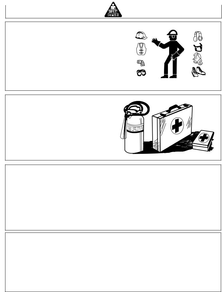
wear protective clothing
Wear close fitting clothing and safety equipment appropriate to the job.
Wear a suitable hearing protective device such as earmuffs or earplugs to protect against objectionable or uncomfortable loud noises.
Operating equipment safely requires the full attention of the operator. Do not wear radio or music headphones while operating machine.
prepare for emergencies
Keep a first aid kit and fire extinguisher handy.
Keep emergency numbers for doctors, ambulance service, hospital and fire department near your telephone.
Be prepared if a fire starts.
inspect UNIT
Be sure all covers, guards and shields are tight and in place.
Locate all operating controls and safety labels.
Inspect power cord for damage before using. There is a hazard of electrical shock from crushing, cutting or heat damage.
service UNIT safely
Before servicing the unit, disconnect all equipment and battery (if equipped) and allow unit to cool down.
Service unit in a clean dry flat area.
Operator’s Manual |
13 |

SAFETY SIGNS
34-1285 Location: Baseplate
34-1615 Location: Baseplate
WARNING |
ADvERTENCIA |
RISK OF BURNS |
RIESGO DE QUEMAR |
MUFFLER AND |
EL AMORTIGUADOR Y LAS |
ADJACENT AREAS |
AREAS ADYACENTES PUEDEN |
MAY EXCEED 50°F. |
TENER TEMPERATURAS POR |
4-059 -0 0699-E/S-ENG. |
ARRIBA DE 50°F. |
34-0598 Location: Engine
 CAUTION/PRECAUCION
RISK OF FIRE |
RIESGO DE FUEGE |
|
Do not add fuel when |
No ponga combustible cuando |
|
product is operating. Allow |
el producto este en operacion. |
|
engine to cool for two ( ) |
Permita que el motor se enfrie |
|
minutes before refueling. |
por minutos antes de |
|
reablastecer de combustible. |
||
|
||
|
4-0599-E/S-0 0600-ENG |
34-0599 Location: Engine
 WARNING/ADVERTENCIA
Do not operate unit |
No opere la unidad sin |
without beltguard in |
todas la cubierta correa en |
place. |
su sitio. |
|
34-0826-E/S-030600-ENG. |
34-0826 Location: Beltguard
34-1284 Location: Baseplate
|
|
|
|
|
|
|
|
|
|
|
|
|
|
|
|
|
|
|
|
|
|
|
|
|
|
|
|
|
|
|
|
|
|
|
|
|
|
|
|
|
|
|
|
|
|
|
|
|
|
|
|
|
|
|
|
|
|
|
|
|
|
|
|
|
|
|
|
|
|
|
|
|
|
|
|
|
|
|
|
|
|
|
|
|
|
|
|
|
|
|
|
|
|
|
|
|
|
|
|
|
|
|
|
|
|
|
|
|
|
|
|
|
|
|
|
|
|
|
34-1616 |
|
34-1286 |
|
|
|
|
||||||||||
|
|
Location: Generator |
|
|
|
|
|
|
Location: Beltguard |
|||||||
14 |
Operator’s Manual |

Controls
controls
B
A
 C
C
D
 E G
E G
F 
I 
 H
H
A -- |
Generator |
D -- |
Handle |
G -- |
Beltguard |
B -- |
Pump |
E -- |
Fuel Tank |
H -- |
Tank Drain Valve |
C -- |
Oil Sight Glass |
F -- |
Engine |
I -- Pressure Gauge |
|
Operator’s Manual |
15 |
Installation
installation
Read safety warnings before setting-up the unit.
Ensure the oil level in the unit's pump is adequate. If low, add SAE-30W non-detergent oil.
LOCATION:
In order to avoid damaging the unit, do not incline the unit transversely or longitudinally more than 10°.
WARNING: RISK OF ASPHYXIATION! DO NOT operate in an enclosed area. Use this product only in well ventilated areas! The exhaust from the engine contains carbon monoxide,apoisonous, odorless and invisible gas. Breathing the gas can cause serious injury, illness and possible death.
WA R N I N G : R I S K O F E X P L O S I O N O R F I R E CAUSING SERIOUS INJURY OR DEATH! Do not allow the engine or muffler to come in contact with flammable vapors, combustible dust, gases or other combustible materials. A spark may cause a fire.
When using the unit for spray painting, place the unitas faraway from the work area as possible, using extra air hoses if needed.
Place unit at least 12 inches away from obstacles that may prevent proper ventilation. Do not place unit in an area:
-where there is evidence of oil or gas leaks.
-where flammable gas vapors or materials may be present.
-where air temperatures fall below 32°F or exceed 104°F.
-where extremely dirty air or water could be drawn into the unit.
16 |
Operator’s Manual |

Installation
GROUNDING INSTRUCTIONS
This product must be grounded. If it should malfunction or breakdown, grounding provides a path of least resistance for electric current to reduce the risk of electric shock.
DANGER: IMPROPER CONNECTION OF THE EQUIPMENT - Grounding conductor can result in a risk of electrocution. Check with aqualified electrician or service person if you are in doubt as to whether the unit is properly grounded.
The screw and ground terminal on the frame must always be used to connect the unit to a suitable ground source. The ground path should be made with #8 size wire. Connect the terminal of the ground wire between the star washers and screw then tighten the screw fully. Connect the other end of the wire securely to a suitable ground source.
The National Electric Code contains several practical ways in which to establish a good ground source. Examples given below illustrate a few of the ways in which a good ground source may be established.
A metal underground water pipe in direct contact with the earth for at least 10 feet can be used as a grounding source. If a pipe is unavailable, an 8 foot length of pipe or rod may be used as the ground source. The pipe should be 3/4 inch trade size or larger and the outer surface must be noncorrosive. If a steel or iron rod is used it should be at least 5/8 inch diameter and if a nonferrous rod is used it should be at least 1/2 inch diameter and be listed as material for grounding. Drive the rod or pipe to a depth of 8 feet. If a rock bottom is encountered less than 4 feet down, bury the rod or pipe in a trench. All electrical tools and appliances operated from this unit, must be properly grounded by use of a third wire or be “Double Insulated”.
It is recommended to:
1.Use electrical devices with 3 prong power cords.
2.Use an extension cord with a 3 hole receptacle and a 3 prong plug at the opposite ends to ensure continuity of the ground protection from the unit to appliance.
John Deere strongly recommend that all applicable federal, state and local regulations relating to grounding specifications be checked and followed.
LINE TRANSFER SWITCH:
If this unit is used for standby service, it must have a transfer switch between the utility power service and the unit. The transfer switch not only prevents the utility power from feeding into the unit, but also prevents the unit from feeding out into the utility company’s lines. This is intended to protect the serviceman who may be working on a damaged line.
THIS INSTALLATION MUST BE DONE BY A LICENSED ELECTRICIAN AND ALL LOCAL CODES MUST BE FOLLOWED.
Operator’s Manual |
17 |

Installation
GASOLINE ENGINE
Review "Risk of Fire or Explosion" before fueling. Read the engine manual accompanying this unit for correct engine start-up maintenance procedures. Read and understand the safety labels located on the unit.
WARNING: RISK OF EXPLOSION OR FIRE CAUSING SERIOUS INJURY OR DEATH! Do not smoke while fueling!
Do not fill fuel tank while the unit is running or hot. Allow the unit and engine to cool down for two minutes before refueling.
Do not fill fuel tank to point of overflowing. Allow approximately 1/4" of tank space for fuel expansion.
Do not place unit in an area where flammable gas vapors may be present. A spark could cause an explosion or fire.
Always store fuel away FROM THE unit while it is running or hot.
WARNING: RISK OF EXPLOSION OR FIRE CAUSING SERIOUS INJURY OR DEATH Do not allow the engine or muffler to come in contact with flammable vapors, combustible dust, gases or other combustible materials. A spark may cause a fire.
When using the unit for spray painting, place the unit as far away from the work areaas possible, using extraair hoses if needed.
A minimum of 86 octane fuel is recommended for use with this air compressor. Do not mix oil with gasoline.
Use of clean, fresh, lead free gasoline is recommended. Leaded gasoline may be used if lead free is not available. Do not use gasoline containing methanol or alcohol.
Refer to the engine manual for all necessary maintenance and adjustments.
18 |
Operator’s Manual |

Installation
HIGH ALTITUDE
At high altitude, the standard carburetor air/fuel mixture will be too rich. Performance will decrease, and fuel consumption will increase. A very rich mixture will also foul the spark plug and cause hard starting. Operation at an altitude that differs from that at which this engine was certified, for extended periods of time, may increase emissions.
High altitude performance can be improved by specific modifications to the carburetor. If you always operate your unit at altitudes above 5,000 feet (1,500 meters), have your dealer perform this carburetor modification.This engine, when operated at high altitude with the carburetor modifications for high altitude use, will meet each emission standard throughout its useful life.
Even with carburetor modification, engine horsepower will decrease about 3.5% for each 1,000-foot (300-meter) increase in altitude. The effect of altitude on horsepower will be greater than this if no carburetor modification is made.
NOTE: When the carburetor has been modified for high altitude operation, the air/fuel mixture will be too lean for low altitude use. Operation at altitudes below 5,000 feet (1,500 meters) with a modified carburetor may cause the engine to overheat and result in serious engine damage.
For use at low altitudes, have your servicing dealer return the carburetor to original factory specifications.
Operator’s Manual |
19 |

Operation
Operation
Pre-Operation:
Check the engine oil level before starting. (See engine manual.) Fill the fuel tank according to the engine manual instruction.
Pump oil level should be checked before each use. Check the oil level indicator on the pump crankcase. Make certain the oil is in the center of the oil sight glass. If the level appears to be low, fill with SAE20 or 30 non-detergent pump oil.
Remove any moisture in the unit's air tank.
WARNING: NEVER attempt to open the Air Tank Drain Valve when more than 10 PSI of air pressure is in the air tank!
Remove excessive pressure with an air tool, then open the Air Tank Drain Valve in the bottom of the air tank. Close tightly when drained.
Make sure the Engine Switch is in the "OFF" position.
Make sure the Safety Relief Valve is working correctly.
Make sure all guards and covers are in place and securely mounted.
20 |
Operator’s Manual |
Operation
Operation
Operation:
1. Read safety warnings before performing operation.
NOTE: Unplug all equipment from the power receptacles before starting the unit.
2.Flip the toggle on top of the Pilot Valve to the upright position. This provides a loadless start. The unit will unload and allow easier engine start-up.
3.Start the engine. (Refer to the Engine Manual accompanying this unit.)
4.When the engine has run for 1-2 minutes, flip toggle back to the original position.
5.Set pressure by adjusting the Pressure Regulator counterclockwise for less pressure and clockwise for more pressure.
6.Make sure the unit is grounded. See Grounding Instructions.
7.Loads can now be applied to the unit.
NOTE: This engine is equipped with a “Low Oil” shutdown system for engine protection. The engine stops when the oil level gets too low. The engine will not restart without adding oil.
If you notice any unusual noise or vibration, stop the unit and refer to "Troubleshooting".
Shutdown:
1.Remove all load by turning off electrical appliances and unplugging electric cords.
2.Move the Engine Switch to the "Off" position. (Refer to the Engine Manual accompanying this unit.)
3.Drain air from the air tanks by releasing air with an attached air tool or by pulling on the Safety Relief Valve.
4.Once the Air Tank Pressure Gauge registers under 10 pounds, open the drain valve under each air tank to drain any moisture.
5.Allow the unit to cool down.
6.Wipe the unit clean and store in a safe, non-freezing, dry area.
Operator’s Manual |
21 |

Operating the Unit
operation
CABLE SIZE:
Equipment damage can result from low voltage. Therefore, to prevent excessive voltage drop between the unit and the equipment, the cable should be of adequate gauge for the length used. The cable selection chart gives the maximum cable lengths for various gauges of wire which can adequately carry the loads shown.
CURRENT |
LOAD IN WATTS |
|
MAXIMUM CABLE LENGTH (FEET) |
|
|||
IN AMPS |
120 VOLTS |
240 VOLTS |
#8 WIRE |
#10 WIRE |
#12 WIRE |
#14 WIRE |
#16 WIRE |
|
|
|
|
|
|
|
|
2.5 |
300 |
600 |
|
1000 |
600 |
375 |
250 |
5 |
600 |
1200 |
|
500 |
300 |
200 |
125 |
|
|
|
|
|
|
|
|
7.5 |
900 |
1800 |
|
350 |
200 |
125 |
100 |
10 |
1200 |
2400 |
|
250 |
150 |
100 |
50 |
15 |
1800 |
3600 |
|
150 |
100 |
65 |
|
20 |
2400 |
4800 |
175 |
125 |
75 |
50 |
|
25 |
3000 |
6000 |
150 |
100 |
60 |
|
|
30 |
3600 |
7200 |
125 |
65 |
|
|
|
40 |
4800 |
9600 |
90 |
|
|
|
|
|
|
|
|
|
|
|
|
ELECTRIC MOTOR LOADS:
It is characteristic of common electric motors in normal operation to draw up to six times their running current while starting. This table may be used to estimate the watts required to start “CODE G” electric motors.
CAUTION: If an electric motor fails to start or reach running speed, turn off the appliance or tool immediately to avoid equipment damage. Always check the requirements of the tool or appliance being used compared to the rated output of the unit.
|
|
WATTS REQUIRED TO START MOTOR |
||
MOTOR (H.P.) |
RUNNING WATTS |
REPULSION INDUCTION |
CAPACITOR |
SPLIT PHASE |
|
|
|
|
|
1/8 |
275 |
600 |
850 |
1200 |
1/6 |
275 |
600 |
850 |
2050 |
|
|
|
|
|
1/4 |
400 |
850 |
1050 |
2400 |
1/3 |
450 |
975 |
1350 |
2700 |
1/2 |
600 |
1300 |
1800 |
3600 |
|
|
|
|
|
3/4 |
850 |
1900 |
2600 |
|
1 |
1100 |
2500 |
3300 |
|
|
|
|
|
|
22 |
Operator’s Manual |

Troubleshooting
Symptom |
Problem |
Solution |
Engine will not start. |
Various engine problems. |
Refer to the engine manual |
|
|
accompanying your unit. |
Noisy operation. |
Loose engine pulley or pump flywheel. Tighten pulley and or flywheel. |
|
|
Lack of oil in the pump. |
Add correct amount of oil. Check |
|
|
for bearing damage. |
|
Carbon deposits on pistons or valves. |
Remove cylinder head and inspect. |
|
|
Clean or replace. |
|
Bearing, piston or connecting rod failure. STOP THE Unit! Contact John Deere |
|
|
|
customer service. |
Pressure drop in air tank or |
Air leaks at connections. |
Allow the unit to build pressure to the |
rapid pressure loss when the |
|
maximum allowed. Turn off and brush |
unit is shut off. |
|
a soapy water solution onto all |
|
|
connections. Check connections for |
|
|
air bubbles. Tighten the connections |
|
|
where leaks are present. |
|
Air leak in air tank. |
Air tank must be replaced. Do not |
|
|
attempt to repair air tank! |
|
Defective Pilot Valve. |
Clean or replace. |
Insufficient pressure at air |
Pressure Regulator not turned to |
Adjust Pressure Regulator to proper |
tool or accessory. |
high enough pressure or defective. |
setting or replace. |
|
Restricted air intake. |
Clean or replace Air Intake Filter. |
|
Air leaks or restrictions. |
Check for leaks and repair. |
|
Hose or hose connections are too |
Replace with larger hose or |
|
small or long. |
connectors. |
|
Slipping belt. |
Tighten or replace. |
|
The unit is not large enough for air |
Check the accessory air requirement. |
|
requirement. |
If it is higher than the CFM or pressure |
|
|
supply to the air compressor, use a |
|
|
larger unit. |
|
Restriction in Pilot Valve. |
Clean or replace. |
Operator’s Manual |
23 |

Troubleshooting
Symptom |
Problem |
Solution |
Unit has no output. |
Circuit breakers tripped. |
Reset circuit breakers. |
|
Inadequate cord sets or |
Check cord sets or extension cords |
|
extension cords. |
capabilities. |
Air leaks from Safety Relief Valve. |
Possible defective Safety Relief |
Operate Safety Relief Valve manually |
|
Valves. |
by pulling on ring. If it still leaks, it |
|
|
should be replaced. |
|
Excessive air tank pressure. |
Clean, reset or replace Pilot Valve. |
Air leaks at pump. |
Defective gaskets. |
Tighten bolts on compressor head to |
|
|
proper torque or replace gaskets. |
Air blowing from Air Intake Filter. |
Defective inlet (reed) valve. |
Contact your John Deere customer |
|
|
service center. |
Moisture in discharge air. |
Condensation in air tank caused by |
Run the unit a minimum of one hour |
|
high level of atmospheric humidity or |
to prevent condensation buildup. |
|
the unit is not run long enough. |
Drain air tank more often in humid |
|
|
weather and use an air line filter. |
Excessive oil consumption or |
Restricted Air Intake Filter. |
Clean or replace. |
oil in hose. |
|
|
|
The unit on unlevel surface. |
Do not incline the unit more than 10° in |
|
|
any direction while running. |
|
Crankcase overfilled with oil. |
Drain oil. Refill to proper level with |
|
|
SAE-30W non-detergent oil. |
|
Wrong viscosity. |
Drain oil. Refill to proper level with |
|
|
SAE-30W non-detergent oil. |
|
Plugged crankcase breather. |
Clean or replace. |
|
Oil leaks. |
Tighten bolts on compressor to |
|
|
proper torque or replace gaskets. |
|
Worn piston rings or scored cylinder. |
Contact your John Deere customer |
|
|
service center. |
Oil has milky appearance. |
Water in oil due to condensation. |
Change oil and move air compressor |
|
|
to a less humid environment. |
Unit has no output. |
Inadequate cord sets or extension cords. Check cord sets or extension cords |
|
|
|
capabilities in section Maintenance; |
|
|
Cable Size in this manual. Consult |
|
|
your John Deere customer service |
|
|
center. |
24 |
Operator’s Manual |

Maintenance
MAINTENANCE
Read the instruction manual before performing maintenance. Keep all air vents clear.
Keep the unit clean.
DO NOT spray with water.
Periodically check all fasteners and tighten, see the periodic maintenance chart.
The following procedures must be performed when stopping the unit for maintenance or service:
1.Turn off the unit.
2.Disconnect spark plug wire from engine.
3.Open all drains.
4.Wait for the unit to cool before starting service.
Maintenance Chart:
To ensure satisfactory operation over an extended period of time, an engine requires normal maintenance at regular intervals. The Periodic Maintenance Chart below shows periodic inspection and maintenance items and suitable intervals. The bullet mark designates that the corresponding item should be performed at that interval.
NOTE: Some adjustments require the use of special tools or other equipment. An electronic tachometer will facilitate setting idle and running speeds.
Procedure |
Daily |
Weekly |
Monthly |
100 |
200 |
Before |
|
|
|
|
Hours |
Hours |
Storage |
Check Pump Oil Level |
x |
|
|
|
|
|
Check Engine Oil Level |
x |
|
|
|
|
|
Oil Leak Inspection |
x |
|
|
|
|
|
Check Engine Air Filter |
x |
|
|
|
|
|
Drain Condensation in Air Tank (s) |
x |
|
|
|
|
|
Inspect Guards/Covers |
x |
|
|
|
|
|
Check for Unusual Noise/Vibration |
x |
|
|
|
|
|
Check for Air Leaks |
x |
|
|
|
|
|
Check cylinder and head fins for dust and dirt |
x |
|
|
|
|
|
Check battery electrolyte level |
x |
|
|
|
|
|
Check fuel lines (replace if necessary) |
x |
|
|
|
|
|
Clean Exterior of Compressor |
|
x |
|
|
|
|
Inspect Air Filter |
|
x |
|
|
|
|
Inspect Belt |
|
|
x |
|
|
|
Check Safety Relief Valve |
|
|
x |
|
|
|
Change engine oil (••) |
|
|
|
x |
|
|
Clean fuel filter |
|
|
|
x |
|
|
Clean dust and dirt from cylinder and cylinder head fins (•••) |
|
|
|
x |
|
|
Change Pump Oil (•) |
|
|
|
|
x |
|
Replace Air Filter |
|
|
|
|
x |
|
Check Engine Spark Plug |
|
|
|
|
x |
|
Add fuel stabilizer |
|
|
|
|
|
x |
Run unit dry |
|
|
|
|
|
x |
• The pump oil must be changed after the first 50 hours of operation and every 200 hours or 3 months, whichever comes first. •• The engine oil must be changed after the first 5 hours of operation and every 50 hours or 3 months, whichever comes first.
••• Service more frequently under dusty conditions.
Every 2 years, an Authorized John Deere Service Technician should check the safety valve, intake valves and delivery valves.
Operator’s Manual |
25 |

Maintenance
MAINTENANCE
ENGINE:
The engine for this unit is governed to operate at speeds close to 3600 RPM (60Hz) throughout the operating load range.
WARNING: DO NOT TAMPER WITH THE
GOVERNOR MECHANISM, CHANGE
THE SETTING EXPERIMENTALLY, OR
PUSH THE THROTTLE OPEN IN AN
ATTEMPT TO GENERATE MORE
ELECTRICAL CURRENT; EQUIPMENT
DAMAGE OR PERSONAL INJURY MAY
RESULT.
GOVERNOR SPEED ADJUSTMENT
SHOULD BE MADE ONLY BY A JOHN
DEERE SERVICING DEALER.
CHECKING ENGINE OIL:
Check oil level before each operation and ensure that it is maintained per engine manual.
CHANGING ENGINE OIL:
Change oil after the first 25 hours of operation. Thereafter it should be changed every 50 hours.
1.Make sure the unit is on level ground. Run the engine to warm the oil.
2.Stop the engine.
3.Remove the oil drain plug. (See Fig. 1)
CAUTION: Oil being drained may be hot. To reduce the risk of burn injury, handle with care. Dispose of used oil properly.
4.Drain oil while engine is warm, into a suitable container.
5.Reinstall the oil drain plug.
6.Remove oil gauge and refill with new oil. (Fig. 2)
7.Check the oil level as instructed in the engine manual.
8.Wipe up any spilled oil.
OIL DRAIN PLUG |
(Fig. 1)
UPPER LEVEL |
(Fig. 2)
26 |
Operator’s Manual |

Maintenance
MAINTENANCE
AIR CLEANER:
WARNING: RISK OF FIRE OR EXPLOSION. DO NOT USE GASOLINE OR LOW FLASHPOINT SOLVENTS TO CLEAN THE ELEMENT. CLEAN THE ELEMENT IN A WELL VENTILATED AREA. ENSURE
THAT NO SPARKS OR FLAMES ARE
NEAR THE WORKING AREA, THIS
INCLUDES ANY APPLIANCE WITH A PILOT LIGHT.
CAUTION: NEVER RUN THE ENGINE WITHOUT THE AIR FILTER, SERIOUS DANGER
CAN RESULT.
Check the air cleaner daily or before starting the engine. Check for and correct heavy buildup of dirt and debris along with loose or damaged components.
1.Unscrew the air cleaner cover and remove the elements.
2.Clean the element:
PAPER AIR CLEANER ELEMENT: Do not wash the paper element or use pressurized air, as this will damage the element. Clean by gently tapping the element to remove dust. Replace the element if damaged, bent or extremely dirty. Handle new element carefully; do not use if the sealing surfaces are bent or damaged.
NOTE: Replace the paper element every 100 hours (more often under extremely dusty conditions.)
3.Reinstall the paper air cleaner element. Close air cleaner cover and screw shut.
Operator’s Manual |
27 |

Maintenance
MAINTENANCE
CLEANING AND GAPPING SPARK PLUG:
If the plug is contaminated with carbon, remove it using a plug cleaner or wire brush.
Check the spark plug gap and reset it if necessary. The spark plug gaps are listed below. To change the gap, bend the sideelectrode only, using a spark plug tool. (Fig. 3)
Install and tighten the spark plug. Connect the spark plug lead.
Recommended Spark Plug:
Engine |
Honda |
|
|
Spark Plug |
NGK BPR6ES |
Spark Plug Gap |
0.7 - 0.8 mm (0.03 in.) |
Torque - New |
8.7-10.9 ft-lb |
Torque - Retighten |
16.6-19.5 ft-lb |
BELT TENSION ADJUSTMENT:
To maintain peak performance of your unit, it may be necessary to adjust the belt tension on occasion. Follow the procedure outlined below:
1.Remove the beltguard and loosen the two nuts on each side of the pump or engine. There are a total of 4 nuts.
2.Turn the cap screw clockwise until a 1/2 inch belt deflection is noticed between the pulleys.
3.Tighten the side nuts.
4.Put a straight edge across both pulleys. If necessary, loosen one set of pulley screws and adjust in or out to properly align. Tighten the pulley screws and check the tension again.
5.Replace the beltguard and tighten the fasteners securely.
Spark Plug Gap (See recommendations)
(Fig. 3)
28 |
Operator’s Manual |
 Loading...