


 Loading...
This Manual is Bookmarked
This Manual is Bookmarked
Operating Instructions and Parts Manual
10" Table Saw
Stock Numbers: 708315BTA, -BTB, -BTC, -LSA, -LSB
708315BTA Table Saw shown
ESPAGÑOL – PÁGINA 41
WMH TOOL GROUP
2420 Vantage Drive |
|
|
Elgin, Illinois 60123 |
Part No. M-708315 |
|
Ph.: 800-274-6848 |
Revision D |
08/05 |
www.wmhtoolgroup.com |
Copyright © WMH Tool |
Group |

This manual has been prepared for the owner and operators of a 708315 Table Saw. Its purpose, aside from machine operation, is to promote safety through the use of accepted correct operating and maintenance procedures. Completely read the safety and maintenance instructions before operating or servicing the machine. To obtain maximum life and efficiency from your JET Table Saw, and to aid in using the machine safely, read this manual thoroughly and follow instructions carefully.
Warranty
WMH Tool Group warrants every product it sells. If one of our tools needs service or repair, one of our Authorized Repair Stations located throughout the United States can give you quick service.
In most cases, any one of these WMH Tool Group Repair Stations can authorize warranty repair, assist you in obtaining parts, or perform routine maintenance and major repair on your JET, Wilton, or Powermatic tools.
For the name of an Authorized Repair Station in your area, please call 1-800-274-6848, or visit www.wmhtoolgroup.com
More Information
WMH Tool Group is consistently adding new products to the line. For complete, up-to-date product information, check with your local WMH Tool Group distributor, or visit www.wmhtoolgroup.com
WMH Tool Group Warranty
WMH Tool Group (including JET, Wilton and Powermatic brands) makes every effort to assure that its products meet high quality and durability standards and warrants to the original retail consumer/purchaser of our products that each product be free from defects in materials and workmanship as follow: 1 YEAR LIMITED WARRANTY ON ALL PRODUCTS UNLESS SPECIFIED OTHERWISE. This Warranty does not apply to defects due directly or indirectly to misuse, abuse, negligence or accidents, normal wear-and- tear, repair or alterations outside our facilities, or to a lack of maintenance.
WMH TOOL GROUP LIMITS ALL IMPLIED WARRANTIES TO THE PERIOD SPECIFIED ABOVE, FROM THE DATE THE PRODUCT WAS PURCHASED AT RETAIL. EXCEPT AS STATED HEREIN, ANY IMPLIED WARRANTIES OR MERCHANTIBILITY AND FITNESS ARE EXCLUDED. SOME STATES DO NOT ALLOW LIMITATIONS ON HOW LONG THE IMPLIED WARRANTY LASTS, SO THE ABOVE LIMITATION MAY NOT APPLY TO YOU. WMH TOOL GROUP SHALL IN NO EVENT BE LIABLE FOR DEATH, INJURIES TO PERSONS OR PROPERTY, OR FOR INCIDENTAL, CONTINGENT, SPECIAL, OR CONSEQUENTIAL DAMAGES ARISING FROM THE USE OF OUR PRODUCTS. SOME STATES DO NOT ALLOW THE EXCLUSION OR LIMITATION OF INCIDENTAL OR CONSEQUENTIAL DAMAGES, SO THE ABOVE LIMITATION OR EXCLUSION MAY NOT APPLY TO YOU.
To take advantage of this warranty, the product or part must be returned for examination, postage prepaid, to an Authorized Repair Station designated by our office. Proof of purchase date and an explanation of the complaint must accompany the merchandise. If our inspection discloses a defect, we will either repair or replace the product, or refund the purchase price if we cannot readily and quickly provide a repair or replacement, if you are willing to accept a refund. We will return repaired product or replacement at WMH Tool Group’s expense, but if it is determined there is no defect, or that the defect resulted from causes not within the scope of WMH Tool Group’s warranty, then the user must bear the cost of storing and returning the product. This warranty gives you specific legal rights; you may also have other rights, which vary from state to state.
WMH Tool Group sells through distributors only. WMH Tool Group reserves the right to effect at any time, without prior notice, those alterations to parts, fittings, and accessory equipment, which they may deem necessary for any reason whatsoever.
2
Table of Contents |
|
Warranty........................................................................................................................................................ |
2 |
Warnings ....................................................................................................................................................... |
4 |
Kickback Prevention...................................................................................................................................... |
6 |
Protection Tips from Kickback....................................................................................................................... |
6 |
Specifications ................................................................................................................................................ |
7 |
Definitions and Terminology.......................................................................................................................... |
7 |
Shipping Contents......................................................................................................................................... |
8 |
Contents of the Shipping Cartons ............................................................................................................. |
8 |
Tool Required (Not Included) .................................................................................................................... |
8 |
Assembly..................................................................................................................................................... |
10 |
Where to Begin........................................................................................................................................ |
10 |
Leg Assembly .......................................................................................................................................... |
10 |
Mounting the Shelf................................................................................................................................... |
11 |
Rubber Feet............................................................................................................................................. |
11 |
Installing the Blade Guard and Splitter.................................................................................................... |
12 |
Aligning the Blade Guard and Splitter ..................................................................................................... |
12 |
Saw Blade ............................................................................................................................................... |
13 |
Attaching the Rip Fence .......................................................................................................................... |
13 |
Calibrating the Rip Fence Scale.............................................................................................................. |
13 |
Stamped Steel Extension Wing............................................................................................................... |
14 |
Sliding Extension Wing............................................................................................................................ |
15 |
Left Scale Extension................................................................................................................................ |
16 |
Right Scale Extension ............................................................................................................................. |
16 |
Optional Left Table Support .................................................................................................................... |
17 |
Handwheel Handle .................................................................................................................................. |
17 |
Adjustments ................................................................................................................................................ |
18 |
90 Degree Positive Stop.......................................................................................................................... |
18 |
Scale Calibration ..................................................................................................................................... |
18 |
Adjusting Blade Parallel to Miter Gauge Slots ........................................................................................ |
19 |
Replacing the Blade ................................................................................................................................ |
19 |
Replacing/Adjusting the Drive Belt .......................................................................................................... |
20 |
Miter Gauge Operation............................................................................................................................ |
21 |
Electrical Connections................................................................................................................................. |
21 |
Operating Controls ...................................................................................................................................... |
21 |
Dust Shroud............................................................................................................................................. |
11 |
45 Degree Positive Stop.......................................................................................................................... |
18 |
Operations................................................................................................................................................... |
22 |
Table Saws .......................................................................................................................................... |
22 |
Kickbacks............................................................................................................................................. |
22 |
Rip Sawing........................................................................................................................................... |
23 |
Crosscutting ......................................................................................................................................... |
24 |
Bevel and Miter Operations ................................................................................................................. |
25 |
Dust Collection..................................................................................................................................... |
25 |
Safety Devices ............................................................................................................................................ |
26 |
Feather Board.......................................................................................................................................... |
26 |
Push Stick ............................................................................................................................................ |
26 |
Filler Piece ........................................................................................................................................... |
26 |
Maintenance................................................................................................................................................ |
26 |
Cleaning .................................................................................................................................................. |
26 |
Lubrication................................................................................................................................................... |
27 |
Miscellaneous ............................................................................................................................................. |
27 |
Troubleshooting .......................................................................................................................................... |
27 |
Parts ............................................................................................................................................................ |
27 |
Ordering Replacement Parts................................................................................................................... |
27 |
3

1.Read and understand the entire owner's manual before attempting assembly or operation.
2.Read and understand the warnings posted on the machine and in this manual. Failure to comply with all of these warnings may cause serious injury.
3.Replace the warning labels if they become obscured or removed.
4.This Table Saw is designed and intended for use by properly trained and experienced personnel only. If you are not familiar with the proper and safe operation of a Table Saw, do not use until proper training and knowledge have been obtained.
5.Do not use this Table Saw for other than its intended use. If used for other purposes, WMH Tool Group disclaims any real or implied warranty and holds itself harmless from any injury that may result from that use.
6.Always wear approved safety glasses/face shields while using this Table Saw. Everyday eyeglasses only have impact resistant lenses; they are not safety glasses.
7.Before operating this Table Saw, remove tie, rings, watches and other jewelry, and roll sleeves up past the elbows. Remove all loose clothing and confine long hair. Non-slip footwear or anti-skid floor strips are recommended. Do not wear gloves.
8.Always use the blade guard on all ''through-sawing'' operations. A through-sawing operation is one in which the blade cuts completely through the workpiece.
9.Kickback occurs when the workpiece is thrown towards the operator at a high rate of speed. If you do not have a clear understanding of kickback and how it occurs, DO NOT operate this table saw!
10.Wear ear protectors (plugs or muffs) during extended periods of operation.
11.Some dust created by power sanding, sawing, grinding, drilling and other construction activities contain chemicals known to cause cancer, birth defects or other reproductive harm. Some examples of these chemicals are:
•Lead from lead based paint.
•Crystalline silica from bricks, cement and other masonry products.
•Arsenic and chromium from chemically treated lumber.
12.Your risk of exposure varies, depending on how often you do this type of work. To reduce your exposure to these chemicals, work in a well-ventilated area and work with approved safety equipment, such as face or dust masks that are specifically designed to filter out microscopic particles.
13.Do not operate this machine while tired or under the influence of drugs, alcohol or any medication.
14.Make certain the switch is in the OFF position before connecting the machine to the power supply.
15.Make certain the machine is properly grounded.
16.Make all machine adjustments or maintenance with the machine unplugged from the power source.
17.Remove adjusting keys and wrenches. Form a habit of checking to see that keys and adjusting wrenches are removed from the machine before turning it on.
18.Keep safety guards in place at all times when the machine is in use. If removed for maintenance purposes, use extreme caution and replace the guards immediately.
19.Make sure the Table Saw is firmly secured to the floor or bench before use.
20.Check damaged parts. Before further use of the machine, a guard or other part that is damaged should be carefully checked to determine that it will operate properly and perform its intended function. Check for alignment of moving parts, binding of moving parts, breakage of parts, mounting and any other conditions that may affect its operation. A guard or other part that is damaged should be properly repaired or replaced.
4

21.Provide for adequate space surrounding work area and non-glare, overhead lighting.
22.Keep the floor around the machine clean and free of scrap material, oil and grease.
23.Keep visitors a safe distance from the work area. Keep children away.
24.Make your workshop child proof with padlocks, master switches or by removing starter keys.
25.Give your work undivided attention. Looking around, carrying on a conversation and “horse-play” are careless acts that can result in serious injury.
26.Maintain a balanced stance at all times so that you do not fall into the blade or other moving parts. Do not overreach or use excessive force to perform any machine operation.
27.Use the right tool at the correct speed and feed rate. Do not force a tool or attachment to do a job for which it was not designed. The right tool will do the job better and safer.
28.Use recommended accessories; improper accessories may be hazardous.
29.Maintain tools with care. Keep saw blades sharp and clean for the best and safest performance. Follow instructions for lubricating and changing accessories.
30.Turn off the machine before cleaning. Use a brush or compressed air to remove chips or debris — do not use your hands.
31.Do not stand on the machine. Serious injury could occur if the machine tips over.
32.Never leave the machine running unattended. Turn the power off and do not leave the machine until it comes to a complete stop.
33.Remove loose items and unnecessary work pieces from the area before starting the machine.
Familiarize yourself with the following safety notices used in this manual:
 This means that if precautions are not heeded, it may result in minor injury and/or possible machine damage.
 This means that if precautions are not heeded, it may result in serious injury or possibly even death.
5
 The most common accidents among table saw users, according to statistics, can be linked to kickback, the high-speed expulsion of material from the table that can strike the operator. Kickback can also result in operator’s hands being pulled into the blade.
Kickback Prevention
Tips to avoid the most common causes of kickback:
•Make sure the blade splitter is always aligned with the blade. A workpiece can bind or stop the flow of the cut if the blade splitter is misaligned and result in kickback.
•Use the blade splitter during every cut. The blade splitter maintains the kerf in the workpiece, which will reduce the chance of kickback.
•Never attempt freehand cuts. The workpiece must be fed perfectly parallel with the blade, otherwise kickback will likely occur. Always use the rip fence or crosscut fence to support the workpiece.
•Make sure that the rip fence is parallel with the blade. If not, the chances of kickback are very high. Take the time to check and adjust the rip fence.
•Feed cuts through to completion. Anytime you stop feeding a workpiece that is in the middle of a cut, the chance of binding, resulting in kickback, is greatly increased.
Protection Tips from
Kickback
Kickback can happen even if precautions are taken to prevent it. Listed below are some tips to always follow to protect you if kickback DOES occur:
•Stand to the side of the blade when cutting. An ejected workpiece usually travels directly in front of the blade.
•Wear safety glasses or a face shield. Your eyes and face are the most vulnerable part of your body.
•Never place your hand behind the blade. If kickback occurs, your hand will be pulled into the blade.
•Use a push stick to keep your hands farther away from the moving blade. If a kickback occurs, the push stick will most likely take the damage that your hand would have received.
 Read and understand the entire contents of this manual before attempting assembly or operation! Failure to comply may cause serious injury!
The specifications in this manual are given as general information and are not binding. WMH Tool Group reserves the right to effect, at any time and without prior notice, changes or alterations to parts, fittings, and accessory equipment deemed necessary for any reason whatsoever.
6
Specifications
Stock Numbers.................................................................................... |
708315BTA, -BTB, -BTC, -LSA, -LSB |
Saw Blade Diameter .................................................................................................................................. |
10” |
Arbor Diameter.......................................................................................................................................... |
5/8” |
Blade Tilt ..................................................................................................................................... |
left, 90 – 45º |
Maximum Cutting Depth at 90º .................................................................................................................... |
3” |
Maximum Cutting Depth at 45°.............................................................................................................. |
2-1/2” |
Dado Capacity........................................................................................................................................... |
1/2" |
Table Height (with Stand)........................................................................................................................... |
35” |
Main Table Size .......................................................................................................................... |
28”W x 18”D |
Extension Size (Aluminum)..................................................................................................... |
5 1/2”W x 18”D |
Extension Size (Sheet Metal)........................................................................................................ |
8”W x 18”D |
Blade Speed (no load) ................................................................................................................... |
5000 RPM |
Motor ....................................................................................................................................... |
120VAC, 60Hz |
Gross Weight (BTA) ............................................................................................................................. |
57 lbs. |
Net Weight (BTA) ................................................................................................................................. |
50 lbs. |
Definitions and Terminology
Arbor: Metal shaft that connects the drive mechanism to the blade.
Bevel Edge Cut: Tilt of the saw arbor and blade between 0° and 45° to perform an angled cutting operation.
Blade Guard: Mechanism mounted over the saw blade to prevent accidental contact with the cutting edge.
Crosscut: Sawing operation in which the miter gauge is used to cut across the grain of the workpiece.
Dado Blade: Blade(s) used for cutting grooves and rabbets.
Dado Cut: Flat bottomed groove in the face of the workpiece made with a dado blade.
Featherboard: Device used to keep a board against the rip fence or table that allows the operator to keep hands away from the saw blade.
Kerf: The resulting cut or gap made by a saw blade.
Kickback: An event in which the workpiece is lifted up and thrown back toward an operator, caused when a work piece binds on the saw blade or between the saw blade and rip fence (or other fixed object). To minimize or prevent injury from kickbacks, see the Operating Instructions section.
Miter Gauge: A component that controls the workpiece movement while performing a crosscut of various angles.
Non-Through Cut: A sawing operation that requires the removal of the blade guard splitter,
resulting in a cut that does not protrude through the top of the workpiece (includes Dado and rabbet cuts).
The blade guard and splitter must be re-installed after performing a non-through cut to avoid accidental contact with the saw blade during operation.
Parallel: Position of the rip fence equal in distance at every point to the side face of the saw blade.
Perpendicular: 90° (right angle) intersection or position of the vertical and horizontal planes such as the position of the saw blade (vertical) to the table surface (horizontal).
Push Board/Push Stick: An instrument used to safely push the workpiece through the cutting operation.
Rabbet: A cutting operation that creates an L-shaped channel along the edge of the board.
Rip Cut: A cut made along the grain of the workpiece.
Splitter: Metal plate to which the blade guard is attached that maintains the kerf opening in the workpiece when performing a cutting operation.
Standard Kerf: 1/8" gap made with a standard blade.
Straightedge: A tool used to check that a surface is flat or parallel.
Through Sawing: A sawing operation in which the workpiece thickness is completely sawn through. Proper blade height usually allows a 1/8" of the top of the blade to extend above the wood stock.
7

Shipping Contents
Contents of the Table Saw Carton
Contents of the Shipping Cartons
The contents that are contained in the shipping carton are determined by the model of your purchase which is determined by the three letter suffix following the stock number, which is 708315.
Remove all contents from the shipping carton. Keep the saw table upside down. Do not discard the carton or packing material until the saw is assembled and is running satisfactorily.
Important: Packing material is placed inside the saw to provide support for the motor during shipping and must be removed.
Compare the contents of the shipping carton against the Contents Table (following page) for your particular model. The Index No. in the table corresponds to the items shown above and this is your key for identifying each part.
Tool Required (Not Included)
5mm hex wrench (1 ea)
6mm hex wrench (1 ea)
14mm wrenches (2 ea)
10 mm wrenches (2 ea) or 10mm wrench and socket (1 ea)
Cross-point Screwdriver (1 ea)
Hardware (actual size)
Blade Removal Tools
8

Shipping Contents
Index |
Part No. |
Description |
No. |
|
|
-- |
|
Table Saw |
|
|
|
A |
708315-LEA |
Left Extension Wing Assy |
B |
708315-105 |
Extension Rod |
C |
708315-REA |
Right Extension Wing Assy |
|
|
|
D |
|
Left Scale Extension |
|
|
|
E |
|
Right Scale Extension |
|
|
|
F |
708315-113 |
Stamped Steel Extension Wing |
G |
708315-RFA |
Rip Fence |
|
|
|
H |
708315-MGA |
Miter Gauge |
|
|
|
I |
708818 |
Push Stick |
|
|
|
J |
708315-BGA |
Blade Guard Assembly |
|
|
|
K |
708315-111 |
Leg |
L |
708315-RSA |
Rear Support Assembly |
M |
708315-150 |
Handle |
|
|
|
N |
708315-121A |
Dado Insert |
|
|
|
NN |
708315-159 |
Dust Shroud |
|
|
|
O |
708315-112 |
Shelf |
P |
TS-1482021 |
M6x12 Hex Cap Screw |
|
|
|
S |
708315-158 |
M6 Hex Flange Nut |
|
|
|
T |
TS-1490041 |
M8x25 Hex Cap Screw |
|
|
|
U |
TS-1540061 |
M8 Hex Nut |
|
|
|
V |
TS-2361081 |
M8 Lock Washer |
W |
TS-1550061 |
M8 Flat Washer |
X |
TS-1551021 |
M4 Lock Washer |
|
|
|
Y |
TS-1532032 |
M4x10 Pan Head Screw |
|
|
|
YY |
TS-2284082 |
M4x8 Pan Head Screw |
|
|
|
Z |
TS-1550021 |
M4 Flat Washer |
ZZ |
708315-134 |
Lock Knob |
|
|
|
|
708315-140 |
Arbor Wrench |
|
|
|
|
708315-139 |
Arbor Nut Wrench |
|
|
|
Quantity
BTA |
BTB |
BTC |
LSA |
LSB |
1 |
1 |
1 |
1 |
1 |
|
|
|
|
|
|
|
|
|
1 |
|
|
2 |
2 |
4 |
|
|
1 |
1 |
1 |
|
|
|
|
|
|
|
|
|
1 |
|
|
|
|
|
|
|
1 |
1 |
1 |
|
|
|
|
|
|
1 |
|
|
|
1 |
1 |
1 |
1 |
1 |
|
|
|
|
|
1 |
1 |
1 |
1 |
1 |
|
|
|
|
|
1 |
1 |
1 |
1 |
1 |
|
|
|
|
|
1 |
1 |
1 |
1 |
1 |
|
|
|
|
|
|
|
|
4 |
4 |
|
1 |
1 |
1 |
1 |
1 |
1 |
1 |
1 |
1 |
|
|
|
|
|
1 |
1 |
1 |
1 |
1 |
|
|
|
|
|
|
|
|
|
1 |
|
|
|
|
|
|
|
|
1 |
1 |
|
|
|
12 |
12 |
|
|
|
|
|
|
|
|
16 |
16 |
|
|
|
|
|
|
2 |
|
|
|
|
|
|
|
|
|
2 |
|
|
|
|
|
|
|
|
|
2 |
|
|
|
|
2 |
|
|
|
|
|
2 |
2 |
4 |
|
|
|
|
|
|
|
2 |
2 |
4 |
|
|
|
|
|
|
|
1 |
1 |
2 |
|
|
|
|
|
|
|
2 |
2 |
4 |
6 |
4 |
6 |
6 |
6 |
|
|
|
|
|
1 |
1 |
1 |
1 |
1 |
|
|
|
|
|
1 |
1 |
1 |
1 |
1 |
|
|
|
|
|
Contents Table
9
Assembly
 Do not plug the table saw into the power source until all assembly has been completed! Failure to comply may cause serious injury!
Where to Begin
Each assembly section will start by listing the applicable model(s) for that assembly procedure. The starting point for your particular model, however, is as follows:
Models LSA, LSB: start with Leg Assembly below. |
Figure 1 |
Models BTA, BTB, BTC: start with Installing the |
|
Blade Guard and Splitter on page 12. |
|
Leg Assembly
Models LSA, LSB
Follow these Leg Assembly instructions if you plan to use your saw as a floor model. If this saw is to be used for bench top applications, skip this section and proceed to the Extension Table section.
Tools required – 10mm socket and wrench Referring to Figures 1 and 2:
Required hardware (for each leg): two M6x12 hex cap screws (C) and three M6 flange hex nuts (F).
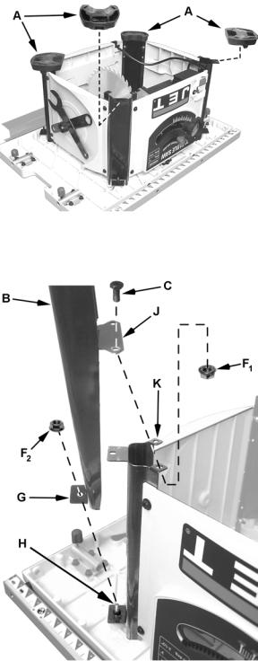
1.With the saw upside down on the floor, remove the four rubber feet (A) from each corner of the base.
2.Take one leg (B) and position it so the outside tab (G), containing the mounting hole, is towards the bottom.
3.Mount one leg to a corner of the saw base so the hole in the outside tab (G) lines up with the screw (H) and the two holes on the leg's inside tab (J) rests on top of the base tabs (K) with the mounting holes lined up.
Note: The leg with the WARNING label must be mounted on the corner of the saw base that also has the WARNING label.
4.Insert two hex cap screws (C) through the mounting holes of the leg tab (J) and base tab
(K). Secure with flange hex nuts (F1). Handtighten only.
Figure 2
5.Secure the leg's outside tab (G) to the screw
(H)on the base with a flange hex nut (F2). Hand-tighten only.
Mount two more legs in the same manner described in steps 1–5. Don't mount the last leg until the shelf is installed as described in the next section.
10
Mounting the Shelf
Models LSA, LSB
Note: The shelf is easier to install when three legs have been assembled. The fourth leg should be assembled after this section is completed.
Required hardware (for assembling all four legs): four M6 flange hex nuts (J).
Referring to Figure 3:
1.While the saw is still upside down, position the shelf (A) between the three legs (B) and below the legs' mounting tabs (D). The sides of the shelf (D) should point down.
2.Bring the shelf up, positioning the tabs of shelf
(E) against the bottom of the mounting tabs on the legs (C), and line up the mounting holes.
3.From underneath the shelf, insert a hex cap screw (F) up through the mounting holes of the shelf and leg tabs. Secure the threaded portion of the screw protruding through the top side of the leg mounting tab with a flange hex nut (J), hand-tightening only at this time.
After the shelf is secured to all three legs, assemble the final leg (described in previous section) and then finish by securing the remaining shelf tab to the leg as well.
2.Press the foot down (2) until the foot "snaps" into position on the leg.
3.Repeat for remaining three legs.
At this time, turn the saw right side up. Place on a level surface and tighten all screws for the leg and shelf assembly.
Figure 4
Dust Shroud
Model LSB only
Note: Install the dust shroud only if a separate dust collection or vacuum system will be used.
Referring to Figure 5:
1.Place the dust shroud (A) inside the legs with the port (B) towards the rear of the saw and positioned down as shown.
2.Bring the front end of the shroud up so the two front tabs (C) catch the lip (D) of the base, securing it in position. The opening at the corners of the shroud (E) should wrap around the leg tabs (F).
3.Press the back of the shroud up until the rear tabs snap into place against lip at the back of the base.
Figure 3
Rubber Feet
Models LSA, LSB
Referring to Figure 4:
While the saw is still upside down,
1.Place rubber foot (B) on the leg (A), sliding forward (1) while at the same time allowing the rear tab (C) of the leg to slide through the
opening (D) in the heel of the rubber foot. |
Figure 5 |
11
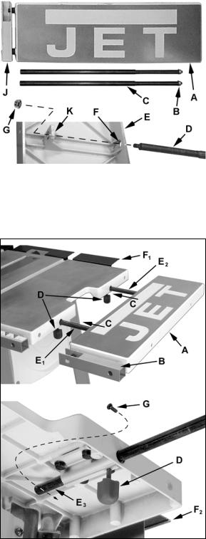
Installing the Blade Guard and Splitter
All models
Referring to Figure 6:
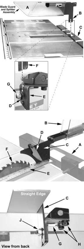
If your table saw came with a back support (C), the blade guard/splitter installation and alignment will be facilitated by loosening and sliding the back support away from the table.
1.Loosen the hex nut (G) on the splitter support bracket (E) to provide sufficient clearance for the blade guard and splitter assembly (next step).
2.Take the blade guard and splitter assembly and slide the tab of the splitter (B and F) on the screw of the splitter support bracket (E) between the flat washer (D) and bracket (E).
3.Tighten the hex nut (G) enough to hold the blade guard and splitter assembly in place.
Adjustment will be required and is described in the
Adjustment section (see Aligning the Blade Guard and Splitter).
Aligning the Blade Guard and Splitter
All models
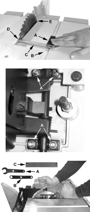
Referring to Figures 7 and 8:
1.Raise the blade guard (B) away from the table.
2.Set a straight edge (E), against the saw blade
(F)on the right side as shown. The anti-kick pawl (D) needs to be lifted momentarily until the straight edge is placed in position.
Note: The straight edge needs to rest against the body of the saw blade and not the saw teeth.
3.With a 10mm wrench, loosen two hex cap screws (H) securing the splitter bracket (G) and adjust the splitter (C) sideways until alignment with the saw blade (F) is achieved.
4.Tighten the hex cap screws (H).
Make sure the splitter (C) is level with the table and approximately 1/8" above the table. A 1/8" space allows the blade guard assembly to tilt to a 45º angle without contacting the table.
If the splitter level needs adjustment:
5.With two 10mm wrenches, loosen the nut and screw (J) assembly, adjust the splitter (C) to 1/8" above the table. Tighten the hardware.
Use a square to verify that the splitter is perpendicular to the table surface and adjust if required.
Figure 6
Figure 7
Figure 8
12
Saw Blade
All Models
The 708315 Table Saw comes with the saw blade already included and installed from the factory. To replace a blade, see Replacing the Blade in the
Adjustments section.
Attaching the Rip Fence
All Models
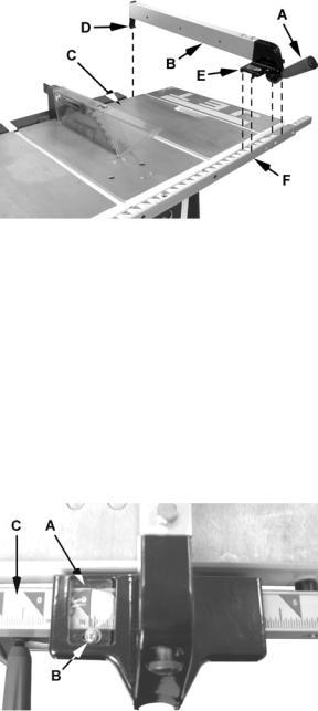
Referring to Figure 9:
1.Raise the rip fence handle (A) as shown.
2.Position the rip fence (B) over the table (C) as shown, holding up the front end while engaging the holding clamp (D) to the rear, then lowering the front end (E) onto the rail (F).
3.Lower the handle (A) to clamp the fence to the table
Calibrating the Rip Fence Scale
All Models
1.Attach the rip fence to the table (as described in the previous section) to the right of the saw blade, but do not lower the handle to clamp the fence to the table.
2.Slide the fence against the saw blade.
You will need to raise the blade guard and the anti-kick pawl to provide clearance for the fence.
3.With the fence snug against the saw blade, clamp the fence in position by lowering the handle.
Referring to Figure 10:
The hairline on the indicator (A) should line up with 0" on the rail (C). If they do not line up:
4.Slightly loosen the screw (B).
5.Slide the indicator until the hairline lines up with 0" on the rail.
6.Tighten the screw.
13
Figure 9
Figure 10
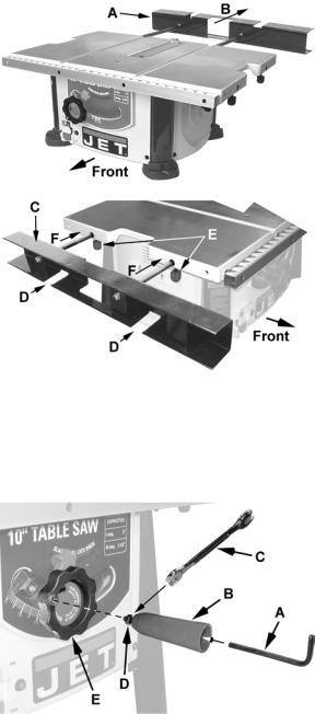
Stamped Steel Extension Wing
Model BTB – the extension wing should look like
(A) in Figure 11
The stamped steel extension wing can be mounted on the right or left side of the saw table. The following steps illustrate the right side.
Installation
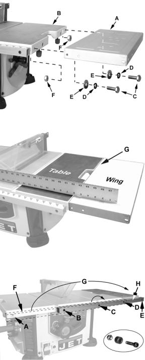
Referring to Figures 11 and 12:
1.Place the stamped steel extension wing (A) against the right side of the saw table (B) so that the mounting holes line up.
2.Place two each M8 lock washers (D) and flat washers (E) on M8 hex cap screws (C).
3.Insert the screws through the mounting holes of the extension wing (A) and table (B).
4.Secure with two M8 hex nuts (F) but leave the assembly loose enough so that the wing can be moved by hand for adjustment.
Adjustment
5.Place a straight edge across the table and extension wing near the front as shown in Figure 12.
6.Raise or lower the extension wing until the straight edge lies flat across the table and wing.
7.Move the straight edge so it lies across the table and wing towards the back (A).
8.Repeat Step 6.
9.When the extension wing is in line with the table at the front and rear, tighten the screws
(C) and hex nuts (F) with two 14mm wrenches.
Repositioning the Front Rail
Refer to Figure 13.
After the stamped steel extension wing is installed, the front rail needs to be repositioned to accommodate the fence when it is positioned over the extension wing. This is done as follows:
Item F, Fig. 13 shows the initial position of the front rail.
1.Using a 5mm hex wrench and a 10mm open end wrench, completely remove the screw, spacer and lock nut (shown in the inset) that secure the rail from the two left and far right mounting holes (A), (B), and (D).
Note: Do not remove mounting hardware from the third mounting hole (C).
Figure 11
Figure 12
Figure 13
2.Rotate the front rail clockwise (G) until the left end becomes the right end in front of the extension wing.
3.Reassemble the three screws, spacers and lock nuts securing the front rail.
The screws are inserted through the front of the rail, the spacers are positioned between the rail and table (or extension), and the lock washers are fastened to the screw from behind the lip of the table (or extension).
14
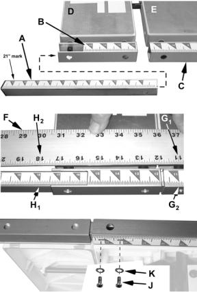
Sliding Extension Wing
Right Wing used on Models BTC, LSA and LSB Left Wing used on Model LSB
Assembly (if required)
Refer to Figure 14.
For saws using the sliding extension wings, two extension rods (C) need to be assembled before mounting to the table. Assembly for the right extension wing (A), identified by no rule on the rail (J), is described below. Assembly for the left wing is the same.
1.Using two 10mm wrenches, remove the lock nut (B) from the extension rods (C and D).
2.Turn the extension wing (A) over so the JET logo lays face down and the mounting holes and tabs (F,K) are visible.
3.Insert the rods (D) through the mounting holes on the extension wing (F) and tab (K)
The threaded end of the rod (D) should protrude through the hole in the tab (K).
4.Place hex nuts (G) on the threaded ends of the extension rods (D), leaving loose enough to rotate the rods by hand.
5.Rotate the extension rods so that the threaded holes, located near the ends away from the extension table, are in line with the top of the extension table.
6.Secure the extension rods with two 10mm wrenches, placing one wrench on the hex nut and the other on the flat indents of the rod.
7.Repeat the above steps for the left extension wing for models that include it.
Mounting the Right Extension Wing Assembly
Models BTC, LSA and LSB – the right extension wing looks like A in Figure 15
Referring to Figure 15:
1.Select the right extension table (A), which is identified by no scale on the guide rail (B).
2.Mount the extension table by sliding the extension rods into the mounting holes (C) on the right side of the saw table. The lock knobs (D) may need to be loosened.
3.From the bottom of the table, thread an M4x8 pan head screw (G) into the hole near the end
of the rear extension rod (E3). This is the rod closest to the rear extension (F1 and F2).
4.Tighten the lock knobs (D).
15
Figure 14
Figure 15
Mounting the Left Extension Wing Assembly
Model LSB only
The left extension table, identified by the scale
(B, Fig. 16) on the rail, is used only with model LSB The assembly and mounting procedure is the same manner as for the right extension wing (above).
Left Scale Extension
Model LSB only
Referring to Figures 16:
1.If necessary, loosen the extension table lock knobs and slide the extension table (D) flush against the saw table (E).
2.Take the left rail extension (A) identified by scale range 11"–21" and insert into the left extension table guide rail (B), sliding it all the way through and into the table guide rail (C).
3.View from underneath and adjust until the two holes in the rail extension (A) and table rail (C) are aligned.
4.Insert two each M4x10 pan head screws (J), M4 lock washers (K) and M4 flat washers (L) to hold the extension rail in place, but leave loose enough to permit adjustment (following steps).
5.Place a scale or yardstick (F) across the extension table and saw table.
6.Align the 11" mark on the ruler (G1) with the 11" mark on the guide rail (G2) and hold ruler firmly in place while performing the next step.
7.Adjust the rail extension (A) until the 18" mark
(H1) is aligned with the 18" mark on the ruler (H2). Release the ruler while making sure the rail extension does not move.
The left rail extension is now properly |
Figure 16 |
calibrated. While holding it in place: |
|
8. Tighten the two screws (K). |
|
Right Scale Extension
Models BTC, LSA and LSB
The assembly steps are the same as for the Left Scale Extension. For the alignment, use 14" and 21" as the calibration marks.
16
Optional Left Table Support
Models BTB, BTC and LSA
Referring to Figure 17:
Table saw models BTB, BTC and LSA do not come with a left extension table. However the rear support assembly (A) can be removed and used as a left table support if needed. To do this:
1.Loosen two lock knobs underneath the back of the table that secure the rear support assembly (A).
2.Remove the rear support assembly by sliding it back (B).
3.Turn the assembly over so that the flat side of the rail is on top (C) and the two notches (D) are on the bottom.
4.Loosen the two lock knobs (E) located on the left side of the table.
5.Install the rear support assembly by inserting
inserting the extension rods into the two mounting holes on the left side of the table (F). Remember that the notches (D) are on the bottom.
7. Tighten the lock knobs.
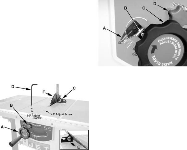
Handwheel Handle
All Models
Referring to Figure 18:
1.Insert a 5mm hex wrench (A) in the end of the handle (B) into the socket head cap screw.
2.Thread into the handwheel (E) until almost tight.
While still maintaining a hold on the hex wrench (A):
3.Tighten the hex nut (C) with a 10mm wrench
(D)against the handwheel (E) so that the handle (B) is secure, but its rotation is still allowed during operation.
17
Figure 17
Figure 18
Adjustments
 When working around the saw blade, always disconnect the saw from the power source! Failure to comply may cause serious injury!
90 Degree Positive Stop
Referring to Figure 19:
1.Turn the handwheel (A) clockwise and raise the blade to its maximum height.
2.Loosen the blade tilt lock knob (B) by turning counterclockwise.
3.Push the handwheel (A) in to engage the blade tilt mechanism; then turn clockwise all the way, bringing the blade to the 90º position to the table.
4.Continue holding the handwheel with the blade in this position. Place a combination square (C) on the table and against the blade as shown.
If the blade is not 90º to the table:
5.While maintaining the hold on the handwheel, use a 6mm hex wrench to turn the 90 Adjust Screw (Figure 19) until the blade is 90º to the table.
6.Tighten the blade tilt lock knob (B).
2.Push the handwheel (C) in to engage the blade tilt mechanism; then turn clockwise all the way, bringing the blade to the 90º position to the table. Hold the handwheel and:
3.Lock the blade tilt lock knob (D).
If the scale does not read exactly 0º:
4.Loosen the screw (B) with an off-set crosspoint screwdriver.
5. Manually adjust the scale (A) until it points to 0º:
6. Tighten the screw (B).
Figure 20
Figure 19
Scale Calibration
The scale next to the handwheel needs to be calibrated after the saw blade has been calibrated at the 90º positive stop (see previous section) and the scale does not indicate 0º.
To calibrate the scale (refer to Figure 20):
1.Loosen the blade tilt lock knob (D) by turning counterclockwise.
45 Degree Positive Stop
Referring to Figure 19:
1.Turn the handwheel (A) clockwise and raise the blade to its maximum height.
2.Loosen the blade tilt lock knob (B) by turning counterclockwise.
3.Push the handwheel (A) in to engage the blade tilt mechanism and turn counterclockwise all the way, bringing the blade to the 45º position to the table.
4.Continue holding the handwheel with the blade in this position. Place a combination square (E) on the table and against the blade as shown.
If the blade is not 45º to the table:
5.While maintaining the hold on the handwheel, use a 6mm hex wrench to turn the 45 Adjust Screw (Figure 19) until the blade is 45º to the table.
6.Tighten the blade tilt lock knob (B).
18
Adjusting Blade Parallel to Miter Gauge Slots
 When working around the saw blade, always disconnect the saw from the power source! Failure to comply may cause serious injury!
The saw blade was adjusted at the factory to be parallel to the miter gauge slots and should not need adjustment. However, if upon inspection it is determined that adjustment is required, follow the steps below.
1.Using the handwheel (A, Fig. 19), raise the saw blade as high as it will go.
Referring to Figure 21:
2.Place the base of a combination square (A) pressed against the edge of the miter slot (B). Extend the sliding rule (C) so it just touches the tooth at the near end of the blade (D), then tighten the locking screw on the combination square to secure the sliding rule.
3.Move the square to the far end of the blade (E).
If a gap appears or if the base of the combination square will not rest against the edge of the miter slot, adjustment is required as follows:
 Saw blades are sharp. Be extremely careful when working around them! Failure to comply may cause serious injury!
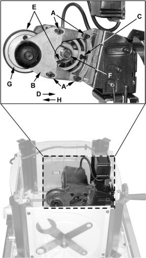
Referring to Figure 22:
4.From underneath the table saw, loosen 3 (of 4) screws (A) that secure the motor to the base.
5.Carefully move the saw blade until the blade is parallel to the miter gauge slot. Check by repeating steps 2 and 3. When adjustment is complete, securely tighten the screws (A).
Replacing the Blade
 When installing or changing the saw blade, always disconnect the saw from the power source! Failure to comply may cause serious injury!
1.Using the handwheels, raise the blade arbor fully and lock the saw at zero degrees (see steps 1–3 in the 90 Degree Positive Stop section); then tighten the blade tilt lock knob (B, Fig. 19).
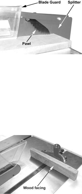
2.Remove the two insert screws and lift the table insert (C, Fig. 23) out of the pocket of the table.
Figure 21
Figure 22
Figure 23
3.Place the open end arbor wrench (A, Fig. 23) on the flat sides of the inside blade flange to keep the saw arbor from rotating. Rotate the arbor nut counterclockwise with the closed arbor nut wrench (B, Fig. 23) and remove the arbor nut and outer flange.
4.Replace the old blade with a new one, making certain that the teeth are pointing down at the front of the table (refer to D, Fig. 21).
5.Assemble the outer flange, arbor nut and securely tighten the arbor nut clockwise while holding the arbor steady with the open end arbor wrench.
19
Replacing/Adjusting the Drive Belt
For Replacement and Adjustment
1.Remove the saw blade (see Replacing the Blade on page 19).
2.Using the front handwheel, lower the blade arbor to its lowest position (rotate handwheel counterclockwise).
3.Remove the blade guard and splitter (see
Installing the Blade Guard and Splitter section on page12), then turn the saw upside down.
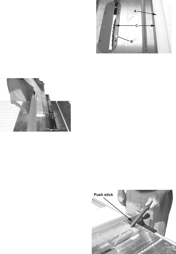
4.Remove the dust shroud if applicable. Referring to Figure 24:
5.With a 5mm hex wrench, loosen four socket head cap screws (A) that secure the arbor support (B) to the motor casing.
If adjusting belt tension only (no belt replacement), skip steps 6 – 10 and proceed to step 11.
6.With a 10mm wrench, loosen the tension adjust screw (C) by turning counterclockwise.
7.Push the arbor support (B) forward (D) to relieve tension on the belt (E).
8.Remove belt (E) from the motor and arbor pulleys (F, G).
9.Replace the old belt with a new belt making sure that it sits properly on both pulleys.
10.Pull the arbor support (B) back (H), placing tension on the belt, and hand-tighten the four mounting screws (A).
Adjustment |
|
||
11. |
With a 10mm wrench, turn the tension adjust |
|
|
|
screw (C) to place proper tension on the belt. |
|
|
|
Adjustment is sufficient when moderate finger |
|
|
|
pressure on the belt between the pulleys |
|
|
|
results in approximately 1/4" deflection. |
Figure 24 |
|
12. |
Tighten the four mounting screws (A) with a |
||
|
|||
|
5mm hex wrench. |
|
|
After the Adjustment
13.Replace the dust shroud (page 11) if applicable.
14.Turn the table saw right-side up.
15.Replace and adjust the blade guard and splitter (refer to the Installing the Blade Guard and Splitter and Adjusting the Blade Guard and Splitter sections on page 12).
16.Replace the saw blade (Replacing the Blade on page 19).
20
Miter Gauge Operation
Operate the miter gauge by loosening the lock knob (A, Fig. 25) and turning the miter body (B, Fig. 25) to the desired angle.
Note: Always make test cuts. Do not rely solely on miter gauge indicator marks.
Electrical Connections
This saw has a motor that operates on 120VAC and is equipped with a power cord that plugs into a standard grounded 3-prong 120VAC
outlet as shown.
Before hooking up to the power source, be sure the switch is in the off position.
If an extension cord is used, select one with a rating appropriate for the
job from the chart below.
12 Gauge Cord |
0 |
– 25 feet |
|
|
|
10 Gauge Cord |
0 |
– 50 feet |
|
|
|
8 Gauge Cord |
0 |
– 100 feet |
|
|
|
Extension Cord Chart
Operating Controls
On/Off Switch – The on/off switch is located on the front panel of the saw base (C, Fig. 26). To turn the saw on move the switch to the up position (F, Fig. 27). To turn the switch off move the switch to the down position.
Locking Key – When the saw is not in use, the switch should be locked in the off position. To lock the switch in the off position, pull out the safety key (G, Fig. 27). The saw will not start with the key removed. However, if the key is removed while the switch is in the on position, it can be turned off once. The saw will not restart until the key has been reinserted into the switch.
Overload Protection – This saw is equipped with a resetable overload relay button (D, Fig. 26). If the motor shuts off or fails to start due to overloading or low voltage, turn the switch (C, Fig. 26) to the off position and let the motor cool down for at least five minutes. After the motor has cooled down, push the reset button (D, Fig. 26) to reset the overload device. The saw should now start when the switch is returned to the on position.
Blade Height/Tilt Handwheel – The handwheel located on the front of the saw (A, Fig. 26) sets the blade height and tilt.
To raise or lower the blade, simply turn the hand-
Figure 25
Figure 26
Figure 27
wheel (A, Fig. 26) clockwise or counterclockwise. To tilt the blade:
1.Press the handwheel in.
2.Loosen the blade tilt lock knob (B, Fig. 26) by turning counterclockwise.
3.Still pressing the handwheel in, turn clockwise or counterclockwise to set the blade between 0º (blade 90º perpendicular to table) and 45º (left tilt).
When the desired blade angle is set,
4.Continue holding the handwheel (A, Fig. 26) in until the lock knob (B, Fig. 26) is tightened.
21
Operations
 Before turning the saw on, make sure that the table is free of tools, hardware and debris. These items can become projectiles and cause serious injury.
Table Saws
Familiarize yourself with the location and operation of all controls and adjustments and the use of accessories such as the miter gauge and rip fence.
Kickbacks
Serious injury can result from kickbacks which occur when a work piece binds on the saw blade or binds between the saw blade and rip fence or other fixed object. This binding can cause the work piece to lift up and be thrown toward the operator.
Listed below are conditions, which can cause kickbacks:
Confining the cutoff piece when crosscutting or ripping.
Releasing the work piece before completing the operation or not pushing the work piece all the way past the saw blade.
Not using the splitter when ripping or not maintaining alignment of the splitter with the saw blade.
Using a dull saw blade.
Not maintaining alignment of the rip fence so that it tends to angle toward rather than away from the saw blade front to back.
Applying feed force when ripping to the cutoff (free) section of the work piece instead of the section between the saw blade and fence.
Ripping wood that is twisted (not flat), or does not have a straight edge, or a twisted grain.
To minimize or prevent injury from kickbacks:
Avoid conditions listed above.
Wear a safety face shield, goggles, or glasses.
Do not use the miter gauge and rip fence in the same operation unless provision is made by use of a facing board (auxiliary block) on the fence so as to allow the cutoff section of the workpiece to come free before the next cut is started (see Figure 35).
22
As the machine receives use, the operation of the anti-kickback pawls should be checked periodically (Figure 26). If the pawls do not stop the reverse motion of a workpiece, resharpen all the points.
Where possible, keep your face and body out of line with potential kickbacks including when starting or stopping the machine.
Figure 28
Dull, badly set, improper, or improperly filed cutting tools and cutting tools with gum or resin adhering to them can cause accidents. Never use a cracked saw blade. The use of a sharp, well maintained, and correct cutting tool for the operation will help to avoid injuries.
Support the work properly and hold it firmly against the gauge or fence. Use a push stick or push block when ripping short, narrow (6" width or less), or thin work. Use a push block or miter gauge hold-down when dadoing or molding.
For increased safety in crosscutting, use an auxiliary wood facing (Figure 29) attached to the miter gauge using the holes provided in the gauge.
Figure 29
Never use the fence as a length stop when crosscutting. Do not hold or touch the free end or cutoff section of a workpiece. On through-
sawing operations, the cutoff section must NOT be confined.
Always keep your hands out of the line of the saw blade and never reach back of the cutting blade with either hand to hold the workpiece.
Bevel ripping cuts should always be made with the fence on the right side of the saw blade so that the blade tilts away from the fence and minimizes the possibility of the work binding and the resulting kickback.
Rip Sawing
Ripping is where the work piece is fed with the grain into the saw blade using the fence as a guide and a positioning device to ensure the desired width of cut (Figure 30).
Figure 30
 Before starting a ripping cut, be sure the fence is clamped securely and aligned properly.
Never rip freehand or use the miter gauge in combination with the fence.
Never rip workpieces shorter than the saw blade diameter.
Never reach behind the blade with either hand to hold down or remove the cutoff piece with the saw blade rotating.
Always use the blade guard, splitter and antikickback pawls. Make sure the splitter is properly aligned. When wood is cut along the grain, the kerf tends to close and bind on the blade and kickbacks can occur.
Note: A caution decal is installed on the guard and splitter assembly warning of the hazard of misalignment.
Figure 31
The rip fence (A, Fig. 31) should be set for the width of the cut (C, Fig. 31) by using the scale on the front rail, or by measuring the distance between the blade (B) and fence (A). Stand out of line with the saw blade and workpiece to avoid sawdust and splinters coming off the blade or a kickback, if one should occur.
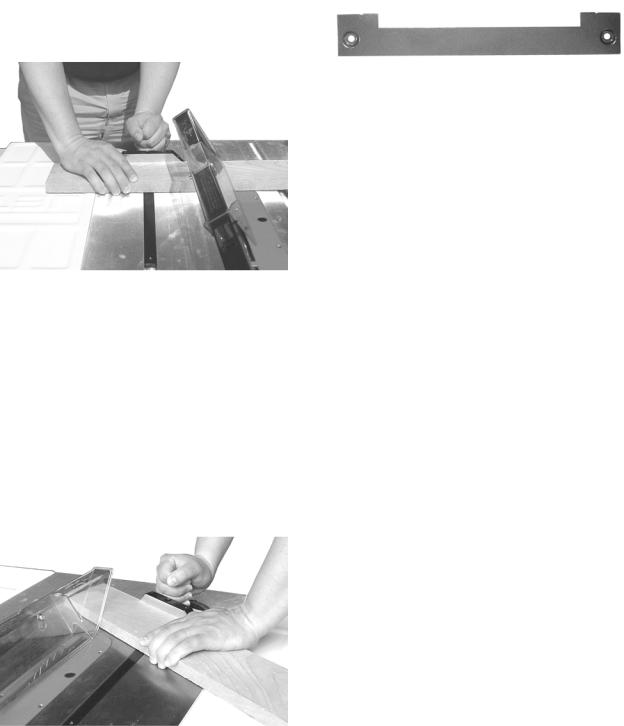
If the work piece does not have a straight edge, nail an auxiliary straight edged board on it to provide one against the fence. To cut properly, the board must make good contact with the table. If it is warped, turn the hollow side down.
In ripping, use one hand to hold the board down against the fence or fixture, and the other to push it into the blade between the blade and the fence. If the workpiece is narrower than 6" use a push stick or push block to push it through between the fence and saw blade (Figure 32). Never push in a location such that the pushing hand is in line with the blade. Move the hand serving as a hold-down a safe distance from the blade as the cut nears completion. For very narrow ripping where a push stick cannot be used, use a push block or auxiliary fence. Always push the workpiece completely past the blade at the end of a cut to minimize the possibility of a kickback.
Figure 32
23
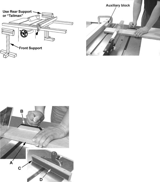
When ripping long boards, use a support at the front of the table, such as a roller stand, and a support or "tailman" at the rear as shown in Figure 33.
Have the blade extend about 1/8" above the top of the workpiece. Exposing the blade above this point can be hazardous.
Crosscutting should never be done freehand nor should the fence be used as an end stop unless an auxiliary block is clamped to the front of the blade area such that the cutoff piece comes free of the block before cutting starts (Figure 35).
Figure 33
Crosscutting
Crosscutting is where the workpiece (A, Fig. 34) is fed cross grain into the saw blade using the miter gauge (B, Fig. 34) to support and position the workpiece.
To improve the effectiveness of the miter gauge in crosscutting, mount an auxiliary wooden extension face (C, Fig, 34) with a glued-on strip of sandpaper (D, Fig. 34) to the miter gauge.
Figure 34
Figure 35
Length stops should not be used on the free end of the workpiece in the cutoff area.
Do not crosscut workpieces shorter than 6". Before starting a cut, be sure the miter gauge is securely clamped at the desired angle. Hold the workpiece firmly against the table and back against the miter gauge. Always use the saw guard and splitter and make sure the splitter is properly aligned.
For 90 degree crosscutting, most operators prefer to use the left-hand miter gauge slot. When using it in this position, hold the workpiece against the gauge with the left hand and use the right hand to advance the workpiece. When using the right hand slot for miter and compound crosscutting so that the blade tilts away from the gauge, the hand positions are reversed.
When using the miter gauge, the workpiece must be held firmly and advanced smoothly at a slow rate. If the workpiece is not held firmly, it can vibrate causing it to bind on the blade and dull the saw teeth.
Provide auxiliary support for any workpiece extending beyond the table top with a tendency to sag and lift up off the table.
Have the blade extend about 1/8" above the top of the workpiece. Exposing the blade above this point can be hazardous.
24
Bevel and Miter Operations
Bevel Cut – A bevel cut is a special type of operation where the saw blade is tilted at an angle less than 90 degrees to the table top (Figure 36). Operations are performed in the same manner as ripping or crosscutting except the fence or miter gauge should be used on the right-hand side of the saw blade to provide added safety in avoiding a binding action between the saw blade and the table top. When beveling with the miter gauge, the workpiece must be held firmly to prevent creeping.
Figure 36
Crosscut – Crosscuts made at an angle to the edge of the workpiece are called miters (Figure 37). Set the miter gauge at the required angle, lock the miter gauge, and make the cut the same as a normal crosscut except the workpiece must be held extra firmly to prevent creeping.
Note: When making compound miters (with blade tilted) use the miter gauge in the right hand slot to provide more hand clearance and safety.
Have the blade extend only 1/8" above the top of the workpiece. Exposing the blade above this point can be hazardous.
Figure 37
Dado Cutting – Dadoing is cutting a wide groove into a workpiece or cutting a rabbet along the edge of a workpiece. A dado insert, shown in Figure 38, is necessary for this type of operation.
 Do not use the standard table insert for dadoing operations.
Figure 38
The process of cutting 1/8" to 1/2" grooves in workpieces is accomplished by the use of a stacked dado blade set or an adjustable type blade mounted on the saw arbor. By using various combinations of the stacked dado blades, or properly setting the dial on an adjustable blade, an accurate width dado can be made. This is very useful for shelving, making joints, tenoning, etc. The guard, splitter, and anti-kickback pawls supplied with the saw should be used for all cutting operations where they can be used. When performing operations where the guard can not be used, as in some dadoing operations, alternative safety precautions should be taken. These include push sticks, feather boards, filler pieces, fixtures, jigs and any other appropriate device that can be utilized to keep operator's hands away from the blade. Upon completion of the operation requiring removal of the guard, the entire guard assembly must be placed back on the machine in its proper working order.
 Never use a dado head in a tilted position. Never operate the saw without the blade guard, splitter and anti-kickback pawls for operations where they can be used.
Dust Collection
If your saw is equipped with a dust shroud, a dust collection or vacuum system (not included) should be used during operation. The port on the dust shroud can accommodate 2.5-inch or 4-inch hoses (Figure 39).
The dust shroud should be checked and cleaned often to remove dust and chips in order to prevent blockage from buildup.
25
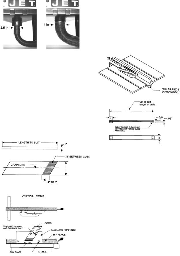
Figure 39
Safety Devices
Feather Board
The feather board (Figure 40) should be made of straight grain hardwood approximately 1" thick and 4" to 8" wide depending on the size of the machine. The length is developed in accordance with intended use. Feather boards can be fastened to the table or rip fence by use of C-clamps. If this method of fastening is used, provide slots in the feather board for adjustment. (The illustration shows a method of attaching and use of the feather board as a vertical comb. The horizontal application is essentially the same except that the attachment is to the table top.)
Figure 40
Push Stick
A push stick is provided with this saw and should be used as an added level of safety for the operator.
Filler Piece
A filler piece (Figure 41) is necessary for narrow ripping and permits the blade guard to remain on the machine. It also provides space for the safe use of a push stick.
Figure 41 – Filler Piece
Maintenance
 Always disconnect power to the machine before performing maintenance. Failure to do this may result in serious personal injury.
Cleaning
Clean the 708315 Table Saw according to the schedule below to ensure maximum performance.
Note: The following maintenance schedule assumes the saw is being used every day.
Daily:
Clean pitch and resin from the saw blade.
Weekly:
Clean motor housing with compressed air.
Wipe down the table surface, grooves and fence rails with a dry silicon lubricant.
26
Loading...