


VM8022
Installation and Operation Manual
160 |
Watts Peak |
|
Watts en Crête |
||
|
||
|
Vatios el Máximo |
|
|
40W x 4 |

VM8022
TABLE OF CONTENTS |
|
Introduction .............................................................................................. |
1 |
Installation ................................................................................................ |
1 |
Wiring ....................................................................................................... |
3 |
Remote Control ........................................................................................ |
4 |
Operation ................................................................................................. |
5 |
Tuner Operation ....................................................................................... |
7 |
Disc/MP3/WMA Playback ........................................................................ |
8 |
System Setup Menu ............................................................................... |
10 |
USB/SD Operation ................................................................................. |
12 |
Care and Maintenance ........................................................................... |
15 |
Troubleshooting ..................................................................................... |
16 |
Specifications ......................................................................................... |
17 |
i

VM8022
ii
VM8022
INTRODUCTION
Congratulations on your purchase of the Jensen VM8022 Mobile Multimedia Receiver. It’s a good idea to read all of the instructions before beginning the installation. We recommend having your Jensen VM8022 installed by a reputable installation shop.
INSTALLATION
This unit is designed for installation in cars, trucks and vans with an existing radio opening. In many cases, a special installation kit will be required to mount the radio to the dashboard. These kits are available at electronics supply stores and car stereo specialty shops. Always check the kit application before purchasing to make sure the kit works with your vehicle. If you have trouble locating a kit or need installation assistance, contact Technical Support at 1-800-323-4815 from 8:30am to 7:00pm EST Monday through Friday and from 9:00am to 5:00pm EST on Saturday.
Tools and Supplies
The following tools and supplies are needed to install the radio:
•Torx type, flathead and Philips screwdrivers
•Wire cutters and strippers
•Tools to remove existing radio (screwdriver, socket wrench set or other tools)
•Electrical tape
•Crimping tool
•Volt meter/test light
•Crimp connections
•18 gauge wire for power connections
•16-18 gauge speaker wire
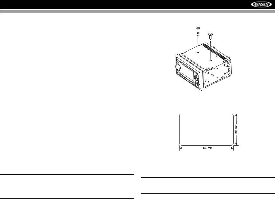
2. Remove Transport Screws
 TRANSPORT SCREWS
Universal Installation
1. Check the dashboard opening size by sliding the radio into it.
Preparation
1.Disconnect Battery
Before you begin, always disconnect the battery negative terminal.
NOTE: If the VM8022 is to be installed in a car equipped with an onboard drive or navigation computer, do not disconnect the battery cable. If the cable is disconnected, the computer memory may be lost. Under these conditions, use extra caution during installation to avoid causing a short circuit.
If the opening is too small, carefully cut or file as necessary until the radio easily slides into the opening. Do not force the radio into the opening. Check for sufficient space behind the dashboard for the radio chassis.
CAUTION: For proper operation of the DVD player, the chassis must be mounted within 20° of horizontal. Make sure the unit is mounted within this limitation.
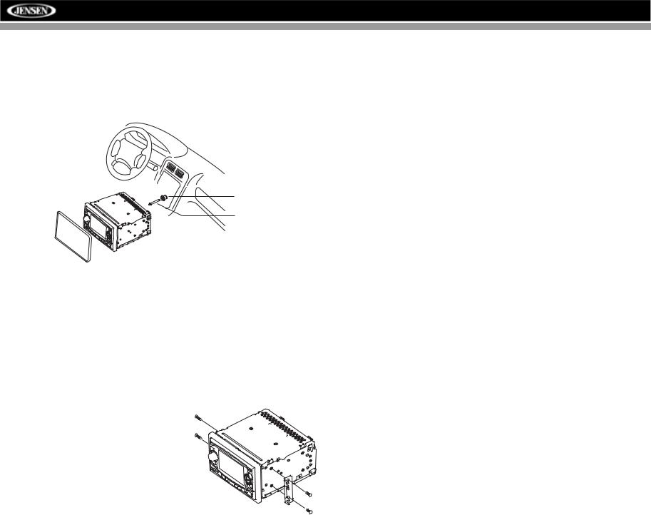
2.Place the radio in front of the dashboard opening so the wiring can be brought through. Follow the wiring diagram carefully and make certain all connections are secure and insulated with wire nuts or electrical tape. See “Wiring” on page 3. After completing the wiring connections,
1
VM8022
turn the unit on to confirm operation (vehicle ignition must be on). If the unit does not operate, re-check all wiring until the problem is corrected.
3.Secure the rear of the unit to the car body using the mounting bolt and rubber cushion.
4.Test the radio using the “Operation” instructions that follow.
RUBBER CUSHION
MOUNTING BOLT
RADIO
TRIM RING
Kit Installation
If your vehicle requires the use of an installation kit to mount this radio, follow the instructions included with the installation kit to attach the radio to the mounting plate supplied with the kit.
1.Wire and test the radio as outlined in the Universal Installation instructions.
2.Install the radio/mounting plate assembly to the sub-dashboard according to the instructions in the installation kit.
3.Replace the dashboard trim panel.
ISO Installation
This unit has threaded holes in the chassis side panels which may be used with the original factory mounting brackets of some vehicles to mount the radio to the dashboard. Please consult with your local car stereo shop for assistance on this type of installation.
1. Remove the existing factory radio from the dashboard or center console
mounting. Save all hardware and brackets as they may be used to mount the new radio.
2.Carefully unsnap the plastic frame from the front of the new radio chassis. Remove and discard the frame.
3.Remove the factory mounting brackets and hardware from the existing radio and attach them to the new radio. Do not exceed M5 x 9mm maximum screw size. Longer screws may damage components inside the chassis.
4.Wire the new radio as outlined in the Universal Installation instructions.
5.Mount the new radio assembly to the dashboard or center console using the reverse procedure of step 1.
Fuses
When replacing a fuse, make sure the new fuse is the correct type and amperage. Using an incorrect fuse could damage the radio.
Reconnect Battery
When wiring is complete, reconnect the battery negative terminal.
Technical Assistance
If you require assistance, contact Technical Support at 1-800-323-4815 from 8:30am to 7:00pm EST Monday through Friday and from 9:00am to 5:00pm EST on Saturday.
2
VM8022
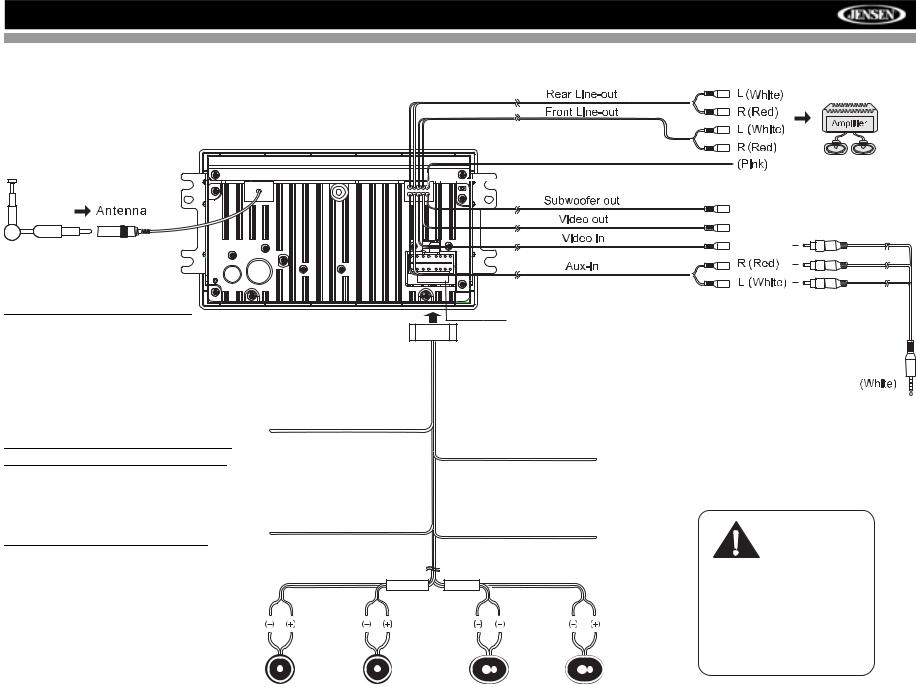
WIRING
NOTE: The amplifier in this
radio is only designed for use with four speakers. Never combine (bridge) outputs for use with two speakers. Never ground negative speaker leads to chassis ground. Failure to wire exactly as shown may cause electrical damage to the radio.
NOTE: Only connect speakers with a nominal impedance of 4 ohms. Speakers with a load
impedance less than 4 ohms could damage the unit.
White/Black
Stripe
Parking
Fuse (15A)
Power Antenna
Connect to power antenna or amplifier.
If not used, tape bare end of wire.
Blue
Accessory/Ignition
Connect to existing radio wire or radio fuse.
Red
FRONT SP |
REAR SP |
|
|
Gray |
Green/Black |
Green Purple/Black |
Purple |
|
Stripe |
Stripe |
|
Left Speaker |
Right Speaker |
Left Speaker |
Right Speaker |
(Front) |
(Front) |
(Rear) |
(Rear) |
(Blue)
(Yellow)
(Yellow)
A/V Media
Adapter Cable
IMPORTANT!
The pink parking wire MUST be connected to the switched side of the parking break circuit (the part that becomes grounded when the brake is applied).
3
VM8022
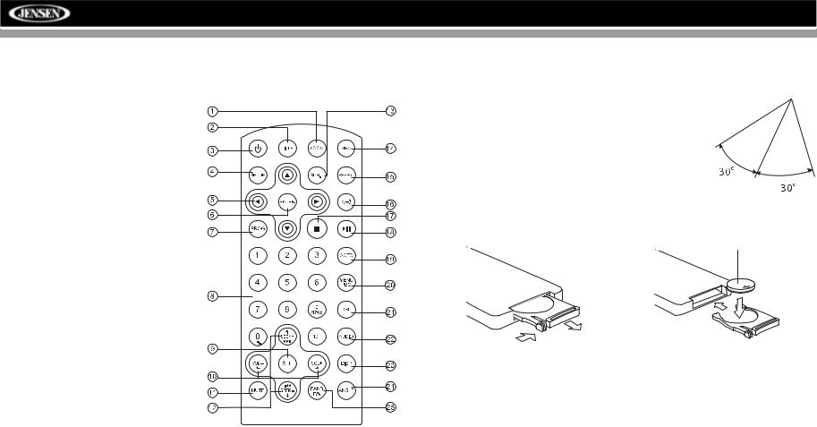
REMOTE CONTROL
The remote control will allow you to control the advanced functions of the VM8022.
1. ZOOM (DVD, VCD only)
2.TITLE (DVD only)
3.Power On/Off
4. SETUP: Access DVD Setup
5. Menu Navigation
6. ENTER
7. PROG: Enter Programmed
Playback mode.
8. Direct Number Entry
9. SEL
•Audio Mode: Select BAS,
TRE, BAL, FAD.
• Press and hold for System Menu
10. Volume Control
11. Mute
12. SEEK
• Radio Tune
• Track Skip/Seek
13. SUB.T: Subtitle (DVD only)
14. SRC: Change Input Source
15. REPEAT
16.A-B Repeat
17.Stop/Return
18.Play/Pause
19.GOTO Search
20.MENU PBC
•DVD Menu
•PBC (for VCD 2.0 and up)
21.OSD: On Screen Display
22.AUDIO
•DVD Audio
•VCD Audio L/R/ST
23.DISP: View On Panel Display
24.ANGLE (DVD only)
25.BAND/P/N
•Video System: PAL, NTSC, AUTO
•Radio Band
Operating Range
The remote control sensor (19) is located to the right of the power button. The remote control can operate within a distance of 3~5m.
Replacing the Battery
When the range of operation of the card remote control becomes short or stops functioning, replace the battery with a new lithium battery. Be sure to observe the proper polarity, as indicated below.
REMOTE SENSOR 
(CR 2025)
1 |
2 |
4
 Loading...