


MSR3007
MARINE AUDIO SYSTEM
Installation and Operation Manual
Manual de la Instalación y Operación / Guide d'installation et d'opération
POWER
MSR3007
VOLUME
|
MODE |
+ |
CAT |
SEL |
CAT |
VOLUME
40W x 4
MUTE |
1 |
2 INT |
3 RPT |
4 RDM |
5 |
EQ |
AUDIO |
IX BASS |
MENU |
|
TUNE/TRK |
INFO |
SEEK |
|
|
SCROLL |
SEEK |
|
TUNE/TRK |
BAND
SEARCH
AUX
IN
6 |
AS/PS |

MSR2007
CONTENTS |
|
Safety Information .............................................................................................. |
1 |
Installation........................................................................................................... |
2 |
Wiring................................................................................................................... |
3 |
Basic Operation .................................................................................................. |
4 |
Tuner Operation.................................................................................................. |
6 |
CD Player Operation........................................................................................... |
7 |
SIRIUS Radio Operation..................................................................................... |
8 |
iPod Operation .................................................................................................... |
9 |
Care and Maintenance...................................................................................... |
10 |
Troubleshooting................................................................................................ |
10 |
Specifications ................................................................................................... |
11 |
CONTENIDO |
|
Información de Seguridad................................................................................ |
13 |
Instalación ......................................................................................................... |
14 |
Cableado............................................................................................................ |
15 |
Operación Básica ............................................................................................. |
16 |
Operación del Sintonizador ............................................................................. |
18 |
Operación del Equipo de CD ........................................................................... |
19 |
Operación de Radio Sirius............................................................................... |
20 |
Operación del iPod ........................................................................................... |
21 |
Cuidado y Mantenimiento ................................................................................ |
22 |
Solución de Problemas .................................................................................... |
22 |
Especificaciones............................................................................................... |
23 |
TABLE DES MATIÈRES |
|
Informations sur la securite............................................................................. |
25 |
Installation......................................................................................................... |
26 |
Cablage.............................................................................................................. |
27 |
Operation de base............................................................................................. |
28 |
Operation tuner................................................................................................. |
30 |
Operation platine CD ........................................................................................ |
31 |
Operation radio Sirius ...................................................................................... |
32 |
Operation iPod .................................................................................................. |
33 |
Soin et entretien................................................................................................ |
34 |
Dépannage ........................................................................................................ |
34 |
Specifications ................................................................................................... |
35 |
ii
MSR3007
SAFETY INFORMATION
When Boating
Keep the volume level Iow enough to be aware of your surroundings.
Protect from Water
Do not expose the product directly to water, as this can cause electrical shorts, fire or other damage.
Protect from High Temperatures
Exposure to direct sunlight for an extended period of time can produce very high temperatures inside your vessel. Give the interior a chance to cool down before starting playback.
Do not mount radio within close proximity of engine compartment.
Use the Proper Power Supply
This product is designed to operate with a 12 volt DC negative ground battery system.
Protect the Disc Mechanism
Avoid inserting any foreign objects into the disc slot. Misuse may cause malfunction or permanent damage due to the precise mechanism of this unit.
CAUTION:
THIS MOBILE CD PLAYER IS A CLASS I LASER PRODUCT. THIS UNIT USES A VISIBLE/ INVISIBLE LASER BEAM WHICH COULD CAUSE HAZARDOUS RADIATION IF EXPOSED DIRECTLY. BE SURE TO OPERATE THE MOBILE CD PLAYER AS INSTRUCTED.
USE OF CONTROLS OR ADJUSTMENTS OR PERFORMANCE OR PROCEDURES OTHER THAN THOSE SPECIFIED HEREIN MAY RESULT IN HAZARDOUS RADIATION EXPOSURE.
DO NOT OPEN COVERS AND DO NOT REPAIR BY YOURSELF. PLEASE REFER SERVICING TO A QUALIFIED TECHNICIAN.
WARNING:
•TO REDUCE THE RISK OF FIRE OR ELECTRIC SHOCK, DO NOT EXPOSE THIS EQUIPMENT DIRECTLY TO WATER.
•TO REDUCE THE RISK OF FIRE OR ELECTRIC SHOCK AND INTERFERENCE, USE ONLY THE RECOMMENDED ACCESSORIES.
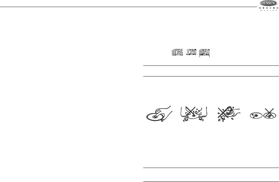
DISC NOTES
Depending on the recording status, conditions of the disc, and the equipment used for recording, some CD-Rs/CD-RWs may not play on this unit. For more reliable playback, please adhere to the following recommendations:
Compatible Disc Types
Table 1: General Disc Information
Disc Type |
|
Logo |
|
Diameter/ |
Playback Time |
|
|
|
Playable Sides |
||||
|
|
|
|
|
|
|
|
|
|
|
|
|
|
|
|
|
|
|
|
|
Audio CD |
|
|
|
|
12 cm single side |
74 minutes |
|
|
|
|
REWRITABLE |
|
|
|
|
RECORDABLE |
|
|
|
|
|
|
|
|
|
|
|
NOTE: CD-R and CD-RW discs will not play unless the recording session is closed and the CD is finalized.
Disc Maintenance
•A dirty or defective disc may cause sound dropouts while playing. Before playing, wipe the disc using a clean cloth, working from the center hole towards the outside edge. Never use benzene, thinners, cleaning fluids, anti-static liquids or any other solvent.
|
|
|
|
|
|
|
|
|
|
Insert label |
Do not bend. |
Never touch |
Wipe clean from |
|
side up. |
|
|
the under side |
the center to the |
|
|
|
of the disc. |
edge. |
|
|
|
|
|
•Be sure to use only round CDs for this unit and do not use any special shape CDs. Use of special shape CDs may cause the unit to malfunction.
•Do not stick paper or tape on the disc. Do not use CDs with labels or stickers attached or that have sticky residue from removed stickers.
•Do not expose discs to direct sunlight or heat sources.
•Use CD-RWs with speed 1x to 4x and write with speed 1x to 2x.
•Use CD-Rs with speed 1x to 8x and write with speed 1x to 2x.
•Do not play a CD-RW which has been written more than 5 times.
NOTE: A disc may become scratched (although not enough to make it unusable) depending on how you handle it and other conditions in the usage environment. These scratches are not an indication of a problem with the player.
1
MSR3007
INSTALLATION
Before You Begin
1.Disconnect Battery
Before you begin, always disconnect the battery negative terminal.
2.Remove Transport Screws
Important Notes
•Before final installation, test the wiring connections to make sure the unit is connected properly and the system works.
•Use only the parts included with the unit to ensure proper installation. The use of unauthorized parts can cause malfunctions.
•Consult with your nearest dealer if installation requires the drilling of holes or other modifications to your vessel.
•Install the unit where it does not interfere with driving and cannot injure passengers if there is a sudden or emergency stop.
•If the installation angle exceeds 30º from horizontal, the unit might not give optimum performance.
•This unit is not waterproof and is intended for interior mounting applications only. Exterior mounting of the unit requires use of an ASA approved marine housing.
•Avoid installing the unit where it will be subject to high temperatures from direct sunlight, hot air, or from a heater, or where it would be subject to excessive dust, dirt or vibration.
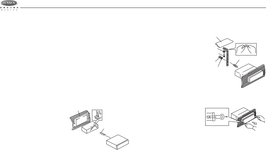
DIN Front Mount
1. Slide the mounting sleeve off of the chas- Dashboard sis if it has not already been removed. If it
is locked into position, use the removal
182
keys (supplied) to disengage it. The removal keys are depicted in “Removing
53
the Unit” on page 2.
2.Check the dashboard opening size by sliding the mounting sleeve into it. If the opening is not large enough, carefully cut or file as necessary until the sleeve easily slides into the opening. Do not force the sleeve into the opening or cause it to bend or bow. Check that there will be sufficient
space behind the dashboard for the radio chassis.
3.Locate the series of bend tabs along the top, bottom and sides of the mounting sleeve. With the sleeve fully inserted into the dashboard opening, bend as many of the tabs outward as necessary to firmly secure the sleeve to the dashboard.
4.Place the radio in front of the dashboard opening so the wiring can be brought through the mounting sleeve.
5.Follow the wiring diagram carefully and make certain all connections are secure and insulated with crimp connectors or electrical tape to ensure proper operation.
6.After completing the wiring connections, turn the unit on to confirm operation (vessel accessory switch must be on). If the unit does not operate, recheck all wiring until the problem is corrected. Once proper operation is achieved, turn the accessory switch off and proceed with final mounting of the chassis.
7.Carefully slide the radio into the mounting sleeve making sure it is right-side-up until it is fully seated and the spring clips lock it into place.
8.Attach one end of the
perforated support strap
(supplied) to the screw stud on |
Dashboard |
|
|
||
the rear of the chassis using |
Support Strap |
|
the hex nut and spring washer |
|
|
provided. Fasten the other end |
Plain Washer |
|
of the perforated strap to a |
Screw (4 x 12mm) |
|
secure part of the dashboard |
||
|
||
either above or below the radio |
Screw Stud |
|
using the screw and plain |
Hex Nut (5mm) |
|
Spring Washer |
||
washer provided. Bend the |
||
|
||
strap, as necessary, to position |
|
|
it. CAUTION: The rear of the |
|
|
radio must be supported with |
|
|
the strap to prevent damage to |
|
|
the dashboard from the weight |
|
|
of the radio or improper |
|
|
operation due to vibration. |
|
9.Test radio operation by referring to the operating instructions for the unit.
Removing the Unit |
Removal Key |
To remove the radio after installation, pull back the rubber covers, insert the removal keys straight back until they click, and then pull the radio out. If removal keys are inserted at an angle, they will not lock properly to release the unit.
Reconnect Battery
When wiring is complete, reconnect the battery negative terminal.
2
MSR3007
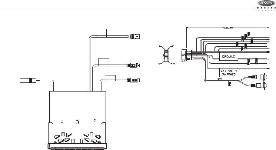
WIRING
TO
SIRIUS
MODULE GRAY
SIRIUS
WIRED
REMOTE BLACK
WIRED REMOTE
BLACK 3" |
TO iPod |
WHITE |
|
IPOD |
|
ANTENNA JACK |
|
VIEW A-A
WIRE INSERTION VIEW
PIN NO. |
WIRE COLOR |
DESCRIPTION |
|
|
|
|
|
|
1 |
GRAY/BLACK |
RIGHT FRONT SPEAKER (-) |
|
|
|
2 |
GRAY |
RIGHT FRONT SPEAKER (+) |
|
|
|
3 |
VIOLET |
RIGHT REAR SPEAKER (+) |
|
|
|
4 |
VIOLET/BLACK |
RIGHT REAR SPEAKER (-) |
|
|
|
5 |
EMPTY |
NO CONNECTION |
|
|
|
6 |
GREEN |
LEFT REAR SPEAKER (+) |
|
|
|
7 |
GREEN/BLACK |
LEFT REAR SPEAKER (-) |
|
|
|
8 |
EMPTY |
NO CONNECTION |
|
|
|
9 |
BLACK/SHIELD |
REAR LINE AUDIO NEGATIVE |
10 |
RED |
REAR RIGHT LINE LEVEL OUT |
11 |
WHITE |
LEFT FRONT SPEAKER (+) |
12 |
WHITE/BLACK |
LEFT FRONT SPEAKER (-) |
13 |
EMPTY |
NO CONNECTION |
14 |
BLUE |
POWER ANTENNA |
15 |
RED |
ACCESSORY/IGNITION (+) |
16 |
BLACK |
GROUND |
17 |
EMPTY |
NO CONNECTION |
18 |
EMPTY |
NO CONNECTION |
19 |
EMPTY |
NO CONNECTION |
20 |
WHITE |
REAR LEFT LINE LEVEL OUT |
|
|
|
Power Antenna
Connect to power antenna or amplifier. If not used, tape bare end of wire.
12V TURN ON +ACC
Connect to existing radio wire or radio fuse.
Chassis Ground
Connect to ground terminal or clean unpainted metal part of chassis.
3
MSR3007
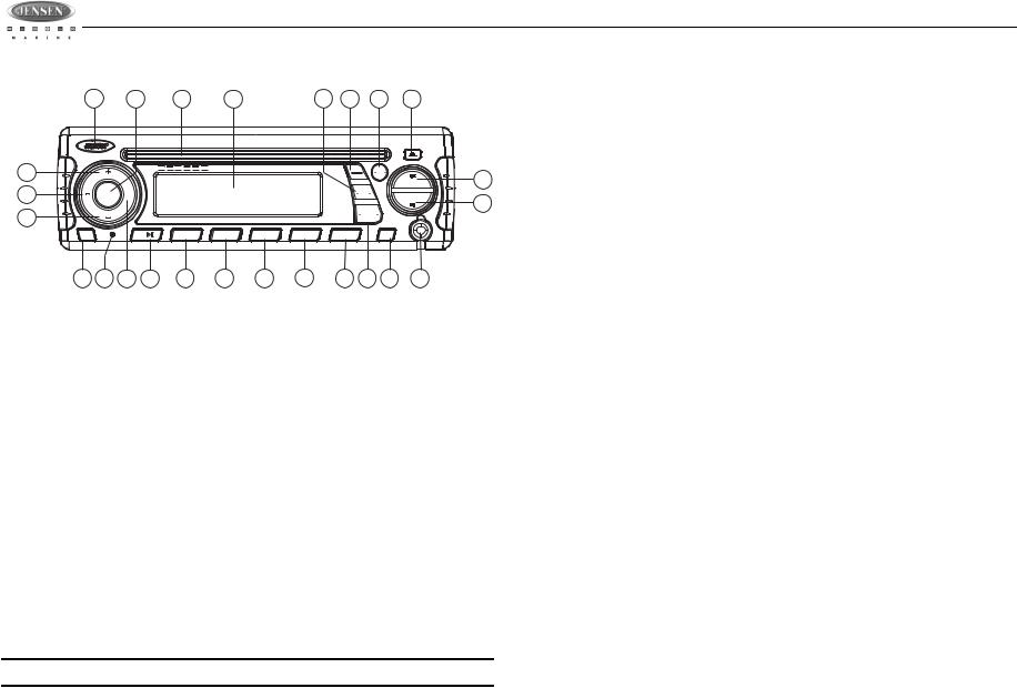
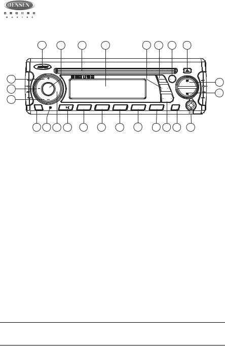
BASIC OPERATION
|
|
|
|
|
Use a ball point pin or thin metal object to press the RESET button (18). This may be |
1 |
4 |
24 |
23 |
12 11 3 22 |
necessary should the unit display an error code. |
|
|
|
|
|
You can recover factory default settings using the RESUME function located on the system |
menu. With “YES” flashing, press the MODE button (4) to activate.
POWER
2a
13
2b


 MSR3007 VOLUME
CAT |
MODE |
+ |
|
|
|
|
SEL |
CAT |
|
|
|
|
|
|
VOLUME |
|
|
|
|
|
|
|
|
|
|
|
40W x 4 |
MUTE |
|
1 |
2 INT |
3 RPT |
4 RDM |
5 |
EQ |
AUDIO |
|
IX BASS |
MENU |
|
|
TUNE/TRK |
|
INFO |
SEEK |
|
SEEK |
||
SCROLL |
||
|
TUNE/TRK |
BAND
SEARCH
AUX
IN
6 |
AS/PS |
|
Audio Menu
Press the AUDIO button (3) on the control panel to access the audio menu. You can navigate
21
through the audio menu items by pressing the AUDIO button repeatedly. Once the desired
20menu item appears on the display, adjust that option by pressing the VOLUME +/- buttons (2) within 5 seconds. The unit will automatically exit the audio menu after five seconds of inactivity.
The following menu items can be adjusted.
Bass Level
Use the VOLUME buttons to adjust the Bass level range from “-6” to “+6”.
17 18 14 |
8 |
6 |
5 |
7 |
9 |
10 16 15 |
19 |
Power On/Off
Press any button on the front panel to turn the unit on. Press the POWER button (1) to turn the unit off.
•If a disc is being inserted when the radio power is off and the ACC (accessory switch) is on, the unit will automatically power up and playback will start.
•If a CD is present, playback resumes at the last position in memory before the ignition was turned off or the POWER button was pressed.
•If no CD is present, the unit will resume at the last mode selected (Tuner, Aux, etc.). The
POWER button is illuminated whenever the IGN lead (red wire) is powered, regardless of whether the unit is on or off.
Volume Control
To increase the volume, press the VOLUME + button (2a). To decrease the volume, press the
VOLUME - button (2b).
Mute
Press the MUTE button (17) on the control panel to mute the audio output. Press MUTE again to restore the audio output to the previous level.
Mode
Press the MODE button (4) on the control panel to select a different mode of operation, as indicated on the display panel. Available modes include Tuner, SIRIUS, CD, iPod and AUX In (optional Auxiliary Input).
NOTE: CD, IPOD, or SIRIUS mode will be skipped if the module is not installed.
Reset
The reset button should be activated for the following reasons:
•initial installation of the unit when all wiring is completed
•function buttons do not operate
•error symbol on the display
Treble Level
Use the VOLUME buttons to adjust the Treble level range from “-6” to “+6”.
Balance
Use the VOLUME buttons to adjust the Balance between the left and right speakers from “L12” (full left) to “R12” (full right).
Fader
Use the VOLUME buttons to adjust the Fader between the rear and front speakers from “R12” (full rear) to “F12” (full front).
Volume Level
Use the VOLUME buttons to adjust the Volume level.
System Menu
1.Press and hold the AUDIO button (3) for more than 3 seconds to enter the system menu. “MENU” will appear on the display, followed by the first menu item, “CONTRAST.”
2.Press the TUNE/TRK >>| or |<< button (21, 20) or press the AUDIO button repeatedly to navigate the system menu and select the desired item.
3.Press the VOLUME +/- buttons (2) to adjust the selected menu item.
4.Press the AS/PS button to return to the previous operation immediately or wait for 5 seconds to return automatically.
The following items can be adjusted:
•CONTRAST (0 – 10): Set LCD contrast.
•LOW BATT (ON/OFF): Monitor voltage on ACC line.
•LOCAL: This mode favors access to local stations whose signals are much stronger, thereby improving radio reception.
•Distant: This is terminate the local receive mode to nomal receive mode
•AREA (USA/LATIN/EUROPE): Set frequency spacing for various regions.
•VOL PGM (0 – 46): Select an automatic turn-on volume.
•BEEP TONE (ON/OFF): Turn the audible beep ON/OFF (heard when functions/buttons are selected). NOTE: Beep tone off will not affect LOW BATT audible tone.
•RESUME: Return the EEPROM to factory default set up values and reset the Sirius Tuner Settings. "Yes" will blink on the LCD to confirm. Press MODE to select.
4

MSR3007
LOW BATTERY Operation
If LOW BATT is set to “ON”, a alarm will sound (8 beeps every 30 sec) when the voltage drops to 10.8V (+/- 0.03V). A visual warning (LOBA) will appear flashing (8 fl ashes every 30 sec) in the lower left corner of the LCD display.
NOTE: “OFF” is the default setting for LOW BATT. If the audio is muted or the volume is set to 0, the audible beep will not be heard.
Equalizer
Press the EQ button (11) to turn on the equalization function and select between five predefined bass and treble curves: OFF > POP > JAZZ > CLASSIC > BEAT > ROCK.
iX-Bass
Press and hold the EQ/IX-BASS button (11) toggle true loudness on/off. When listening to music at low volumes, this feature will boost the bass and treble ranges to compensate for the characteristics of human hearing.
Auxiliary Input
To access an auxiliary device:
1.Connect the portable audio player to the AUX IN on the front panel (19).
2.Press the MODE button (4) to select Aux In mode.
3.Press MODE again to cancel Aux In mode and go to the next mode.
Liquid Crystal Display (LCD)
The current frequency and activated functions are shown on the LCD panel (23).
NOTE: LCD panels may take longer to respond when subjected to cold temperatures for an extended period of time. In addition, the visibility of the numbers on the LCD may decrease slightly. The LCD display will return to normal when the temperature increases to a normal range.
Scroll
When the information is too long to be displayed on the LCD, press and hold the INFO/ SCROLL button (12) to view the entire title. The information will scroll twice and then return to abbreviated text.
Quick Exit Hot Key
In the following modes and conditions, press the AS/PS button < 3 seconds to quickly exit the current operation without waiting for the system default time out:
•System menu operation
•Searching mode
•Audio menu operation
5
|
|
|
MSR3007 |
|
|
|
|
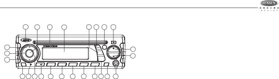
TUNER OPERATION |
|
|
|
|
|
|
Preset Scan |
1 4 24 23 |
12 11 3 22 |
Select a band (if needed). Press AS/PS (15) to scan stations stored in the current band. The |
|
unit will pause for ten seconds at each preset station. Press AS/PS again to stop scanning when the desired station is reached.
POWER
2a |
|
|
|
|
|
|
|
MSR3007 |
|
VOLUME |
|
|
|
|
|
|
|
13 |
|
MODE |
+ |
|
|
|
|
|
CAT |
SEL |
CAT |
|
|
|
|
|
|
|
|
|
|
|
|
|||
2b |
|
VOLUME |
|
|
|
|
|
|
|
|
|
|
|
|
|
|
40W x 4 |
|
MUTE |
|
|
1 |
2 INT |
3 RPT |
4 RDM |
5 |
|
17 18 14 |
8 |
6 |
5 |
7 |
9 |
||
EQ |
AUDIO |
|
IX BASS |
MENU |
21 |
|
SEEK |
|
|
TUNE/TRK |
|
INFO |
|
|
SCROLL |
SEEK |
|
|
TUNE/TRK |
20 |
|
BAND |
|
|
SEARCH |
|
|
AUX |
|
|
IN |
|
6 |
AS/PS |
|
10 16 15 19
Select a Band
Press the BAND button (16) to change between three FM bands and two AM (MW) bands.
Manual Tuning
Press the TUNE/TRK >>| or |<< buttons (20, 21) to seek stations up/down step by step.
Auto Seek Tuning
Press and hold the TUNE/TRK >>| or |<< buttons (20, 21) to automatically seek the next or previous strong station.
Preset Stations
Six numbered preset buttons store and recall stations for each band.
Store a Station
Select a band (if needed), then select a station. Press and hold a preset button (5-10) for two seconds. The preset number will appear in the display.
Recall a Station
Select a band (if needed). Press a preset button (5-10) to select the corresponding stored station.
Automatically Store / Preset Scan (AS/PS)
Automatically Store
Select a band (if needed). Press and hold the AS/PS (15) button for more than three seconds to automatically select six strong stations and store them in the current band. The new stations replace any stations already stored in that band.
NOTE: During Auto Store (AS), the tuner will default to “Local” mode while scanning the band initially. After scanning the entire band once, the unit will switch to “Distant” mode for all subsequent Auto Store tuning.
6
MSR3007
CD PLAYER OPERATION
1 |
4 |
24 |
23 |
12 |
11 |
3 |
22 |
POWER
2a |
|
|
|
|
|
|
|
MSR3007 |
|
VOLUME |
|
|
|
|
|
|
|
13 |
|
MODE |
+ |
|
|
|
|
|
CAT |
SEL |
CAT |
|
|
|
|
|
|
|
|
|
|
|
|
|||
2b |
|
VOLUME |
|
|
|
|
|
|
|
|
|
|
|
|
|
|
40W x 4 |
|
MUTE |
|
|
1 |
2 INT |
3 RPT |
4 RDM |
5 |
|
17 18 14 |
8 |
6 |
5 |
7 |
9 |
||
EQ |
AUDIO |
|
IX BASS |
MENU |
21 |
|
SEEK |
|
|
TUNE/TRK |
|
INFO |
|
|
SCROLL |
SEEK |
|
|
TUNE/TRK |
20 |
|
BAND |
|
|
SEARCH |
|
|
AUX |
|
|
IN |
|
6 |
AS/PS |
|
10 16 15 19
Inserting and Ejecting a Disc
Insert a disc, label-side up, into the disc slot (24) with the unit turned on. The unit will automatically draw the disc in and play the first track on the disc.
Press the eject  button (22) to stop disc play and eject the disc. The unit does not have to be turned on to eject the disc.
Controlling Disc Playback
Selecting Tracks
Press the TUNE/TRK >>| (21) or TUNE/TRK |<< button (20) to advance to the next track on the CD. The selected track number will appear on the display. Press and hold the TUNE/TRK >>| or |<< button to fast forward or fast reverse through the disc. CD play starts when the button is released.
Play/Pause Disc Playback
Press the 1/>|| button (8) to suspend disc play. Press the 1/>|| button again to resume disc Play.
Previewing Tracks
Press the 2/INT button (6) to play the first 10 seconds of each track sequentially. Press 2/INT again to stop Intro Scan and resume normal play at the current track.
Repeat Play
Press the 3/RPT button (5) during disc play to repeat play the current track. Press 3/RPT again to stop repeat play.
Random Play
Press the 4/RDM button (7) during disc play to play all tracks on a CD in random, shuffled order. Press 4/RDM again to stop random play.
7
MSR3007
SIRIUS RADIO OPERATION
Storing Preset Channels
1 |
4 |
24 |
23 |
12 |
11 |
3 |
22 |
2a
13
2b
POWER


 MSR3007 VOLUME
|
MODE |
+ |
|
|
|
|
CAT |
SEL |
CAT |
|
|
|
|
|
VOLUME |
|
|
|
|
|
|
|
|
|
|
|
40W x 4 |
MUTE |
|
1 |
2 INT |
3 RPT |
4 RDM |
5 |
EQ |
AUDIO |
IX BASS |
MENU |
|
TUNE/TRK |
INFO |
SEEK |
|
|
SCROLL |
SEEK |
|
TUNE/TRK |
BAND
SEARCH
AUX
IN
6 |
AS/PS |
The preset buttons (5-10) can be used to store 6 channels, allowing convenient access to your favorite channels.
Programming Channels
1.Select the channel you want to store in memory.
2.Press and hold a preset button (5-10) until the corresponding preset button number
21appears.
3.Repeat steps 1 and 2 to program additional channels.
20Quick Tuning
Press one of the six preset buttons (5-10) to select a preset channel directly.
17 18 14 |
8 |
6 |
5 |
7 |
9 |
10 16 15 |
19 |
Switching to SIRIUS Mode
Press the MODE button (4) to change the mode to Sirius radio mode.
Accessing your SIRIUS ID
1.In Sirius mode, press and hold the BAND/SEARCH button (16) to select DIRECT mode.
2.Press the MODE button (4) to activate Direct mode.
3.Press the MODE button for each digit to enter “000”.
4.Press MODE again to confirm. This will display the Sirius ID number for your tuner.
5.The Sirius ID number will scroll twice and then freeze with the first 11 digits on the display. Press the INFO/SCROLL button (12) to display the remaining digit.
Channel Direct Access Searching
1.Press and hold the BAND/SEARCH button (16) to access Direct Tune mode. “DIRECT-T” appears on the display for a few seconds.
2.Press the MODE button (4) to confirm.
3.Press the TUNE/TRK |<< / >>| buttons (20/21) to move between the three digits.
4.Use the VOLUME +/- buttons (2) to select a number for each position.
5.Press the MODE button to confirm each digit.
6.Press the MODE button again to tune to the selected file.
Alternate Display Information
Press INFO/SCROLL button (12) to change the display information in the following order: ARTIST NAME > SONG TITLE > CATEGORY > CHANNEL NAME.
Satellite Signal Strength
The display will indicate satellite reception strength as shown below.
Selecting a Band
In Sirius mode, press the BAND button (16) to access the Sirius user-preset channel groups in the following order: SR-1, SR-2, SR-3.
Category Tuning
1.Press the CAT - /+ buttons (13/14) to change the category. Each category title and song title will be displayed in increments.
2.While in the category mode, press the CAT - /+ buttons again to view category names. (The lowest channel number within the chosen category will always be the default first channel tuned.)
3.Press the MODE button (4) or the TUNE/TRK |<< / >>| buttons (20/21) to choose desired channels in that category.
4.Press the TUNE/TRK buttons to select a channel within the chosen category.
5.Press MODE to confirm channel selection.
Channel Up/Down Tuning
Press the TUNE/TRK |<< / >>| buttons (20/21) to search for a channel. Press and hold the TUNE/TRK buttons to fast search.
Signal Strength |
Strength Display |
No Signal
Weak
Good
Excellent
8

MSR3007
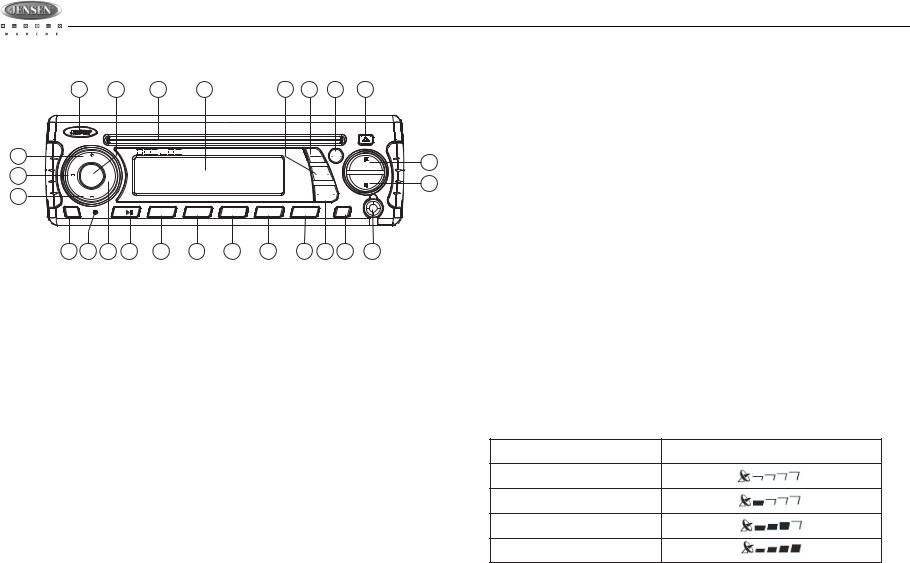
iPod OPERATION
This unit is equipped with an iPod ready function that will allow you to control your iPod (if compatible) using the control panel control buttons. The following iPod versions are supported:
•iPod 3G (firmware version 2.2 only)
•iPod Mini
•iPod 4G
•iPod Photo
•iPod Nano
•iPod 5G (Video)
Controlling Playback
Pausing Playback
During playback, press the 1/>|| button (8) to pause the iPod player. “Pause” will appear on the LCD. Press 1/>|| again to resume playback.
Repeat Play
During playback, press the 3/RPT button (5) to repeat the current song. “Repeat” will appear on the LCD. Press 3/RPT again to stop repeat playback.
Random Play
NOTE: iPod and iPod Cable sold separately.
Accessing iPod Mode
The unit will automatically switch to iPod mode when an iPod is plugged into the iPod cable.
To return to the iPod menu from any other source, press the MODE button (4) on the control panel or remote control until “iPod” appears on the display.
Turning the iPod On/Off
The iPod power turns on automatically when an iPod is connected to 30-pin iPod cable, as long as
the vehicle ignition is turned on. You can turn the iPod off by disconnecting it from the cable or by turning the ignition off. When the ignition is turned
off, the iPod will pause and then enter sleep mode after 2 minutes. While the iPod is connected, the power cannot be turned on or off from the iPod itself.
NOTE: The iPod will continuously recharge when connected to the unit, as long as the vehicle ignition is turned on.
During playback, press the 4/RDM button (7) to play all songs in the current category in random order. Random play will begin once the current song has finished playing. “Shuffle” will appear on the LCD. Press 4/RDM again to stop random playback.
Selecting Tracks
During playback, press the TUNE/TRK |<< / >>| button (20/21) to play the previous or next track in the current category. Press the TUNE/TRK |<< button (20) once to play the song from the start position or press TUNE/TRK |<< twice to play the previous track.
Press and hold the TUNE/TRK |<< / >>| button (20/21) to fast reverse/forward the song.
NOTE: If you press and hold the TUNE/TRK |<< / >>| button to change the current song to the previous/next song, you will exit fast reverse/forward mode.
Alternate Display Information
Press INFO/SCROLL button (12) to change the display information in the following order: ARTIST NAME > SONG TITLE > FOLDER NAME.
Search Mode
Press and hold the BAND/SEARCH button (16) to enter iPod search mode. Press BAND/ SEARCH again to access Playlist, Artist, Album, Genre, Song, or Composer (consecutively).
When search mode is selected, press the MODE button (4) to confirm selection. Use the VOLUME +/- buttons (2) to navigate through various list selections. Press MODE (4) to make your final selection.
1 |
4 |
24 |
23 |
12 |
11 |
3 |
22 |
2a
13
2b
POWER


 MSR3007 VOLUME
|
MODE |
+ |
|
|
|
|
CAT |
SEL |
CAT |
|
|
|
|
|
VOLUME |
|
|
|
|
|
|
|
|
|
|
|
40W x 4 |
MUTE |
|
1 |
2 INT |
3 RPT |
4 RDM |
5 |
EQ |
AUDIO |
IX BASS |
MENU |
|
TUNE/TRK |
INFO |
SEEK |
|
|
SCROLL |
SEEK |
|
TUNE/TRK |
BAND
SEARCH
AUX
IN
6 |
AS/PS |
21
20
17 18 14 |
8 |
6 |
5 |
7 |
9 |
10 16 15 |
19 |
9

MSR3007
CARE AND MAINTENANCE |
TROUBLESHOOTING |
•Keep the product dry. If it does get wet, wipe it dry immediately. Liquids might contain minerals that can corrode the electronic circuits.
•Keep the product away from dust and dirt, which can cause premature wear of parts.
•Handle the product gently and carefully. Dropping it can damage circuit boards and cases, and can cause the product to work improperly.
•Wipe the product with a dampened cloth occasionally to keep it looking new. Do not use harsh chemicals, cleaning solvents, or strong detergents to clean the product.
•Use and store the product only in normal temperature environments. High temperature can shorten the life of electronic devices, damage batteries, and distort or melt plastic parts.
Ignition
The most common source of noise in reception is the ignition system. This is a result of the radio being placed close to the ignition system (engine). This type of noise can be easily detected because it will vary in intensity of pitch with the speed of the engine.
Usually, the ignition noise can be suppressed considerably by using a radio suppression type high voltage ignition wire and suppressor resistor in the ignition system. (Most vessels employ this wire and resistor but it may be necessary to check them for correct operation.) Another method of suppression is the use of additional noise suppressors. These can be obtained from most CB/A radio or electronic supply shops.
Interference
Radio reception in a moving environment is very different from reception in a stationary environment (home). It is very important to understand the difference.
AM reception will deteriorate when passing under a bridge or when passing under high voltage lines. Although AM is subject to environmental noise, it has the ability to received at great distance. This is because broadcasting signals follow the curvature of the earth and are reflected back by the upper atmosphere.
Symptom |
Cause |
Solution |
|
|
|
|
|
|
|
|
|
No power |
The vessel’s accessory |
If the power supply is properly |
|
|
switch is not on |
connected to the vessel’s acces- |
|
|
|
sory terminal, switch the ignition |
|
|
|
key to “ACC”. |
|
|
The fuse is blown |
Replace the fuse. |
|
|
|
|
|
Disc cannot be loaded or |
Presence of CD disc inside |
Remove the disc in the player and |
|
ejected |
the player |
insert the new one. |
|
|
Inserting the disc in reverse |
Insert the compact disc with the |
|
|
direction |
label facing upward. |
|
|
Compact disc is extremely |
Clean the disc or try to play a new |
|
|
dirty or disc is defective |
one. |
|
|
Condensation |
Leave the player off for an hour or |
|
|
|
so, then try again. |
|
No sound |
Volume is too low |
Adjust volume to audible level. |
|
|
|
|
|
|
Wiring is not properly con- |
Check wiring connections. |
|
|
nected. |
|
|
The operation keys do |
Control panel not properly |
Reinstall control panel. |
|
not work |
installed |
|
|
|
The built-in microcomputer |
Press the RESET button. |
|
|
is not operating properly |
|
|
|
due to noise |
|
|
Sound skips |
The installation angle is |
Adjust the installation angle to |
|
|
more than 30 degrees. |
less than 30 degrees. |
|
|
The disc is dirty or defec- |
Clean the disc and try to play |
|
|
tive. |
again or use new disc. |
|
Cannot tune to radio sta- |
The antenna cable is not |
Insert the antenna cable firmly. |
|
tion, auto-seek does not |
connected. |
|
|
work |
|
|
|
The signals are too weak. |
Select a station manually. |
||
|
|||
|
|
|
10
 Loading...