


JDV8035
3.5” TFT Multimedia Player/Receiver
Installation and Operation Manual/Manual d’Utilisateur
JDV8035 |
2 ZONE |
2 ZONE

JDV8035
Pour des instructions en Francais, référez-vous à la page 30.
SAFETY INFORMATION
When Driving
Keep the volume level Iow enough to be aware of the road and traffic conditions.
When Car Washing
Do not expose the product to water or excessive moisture. This could cause electrical shorts, fire or other damage.
 CAUTION: To avoid an accident, the driver must not watch video while driving. This unit is designed to NOT allow video while driving. Park your car in a safe place and engage the parking brake before watching video.
When Parked
Parking in direct sunlight can produce very high temperatures inside your vehicle. Give the interior a chance to cool down before starting playback.
Use the Proper Power Supply
This product is designed to operate with a 12 volt DC, negative ground battery system (the regular system in a North American car).
Protect the Disc Mechanism
Avoid inserting any foreign objects into the slot of this player. Failure to follow this may cause malfunction or permanent damage.
Copyright Protection Notice
This product incorporates copyright protection technology that is protected by method claims of certain U.S. Patents and other intellectual property rights owned by Macrovision Corporation and other rights owners. Use of this copyright protection technology must be authorized by Macrovision Corporation, and is intended for home and other limited viewing uses only unless otherwise authorized by Macrovision Corporation. Reverse engineering or disassembly is prohibited.
CAUTION:
THIS MOBILE DVD PLAYER IS A CLASS I LASER PRODUCT. THIS UNIT USES A VISIBLE/INVISIBLE LASER BEAM WHICH COULD CAUSE HAZARDOUS RADIATION IF EXPOSED DIRECTLY. BE SURE TO OPERATE THE MOBILE DVD PLAYER CORRECTLY AS INSTRUCTED.
USE OF CONTROLS, ADJUSTMENTS, PERFORMANCE AND PROCEDURES OTHER THAN THOSE SPECIFIED HEREIN MAY RESULT IN HAZARDOUS RADIATION EXPOSURE.
DO NOT OPEN COVERS AND DO NOT REPAIR BY YOURSELF PLEASE REFER SERVICING TO A QUALIFIED TECHNICIAN.
WARNING:
•DO NOT EXPOSE THIS EQUIPMENT TO RAIN OR MOISTURE.
•USE ONLY THE RECOMMENDED
ACCESSORIES.
THIS DEVICE IS INTENDED FOR
CONTINUOUS OPERATION.
2
JDV8035
SUPPORTED DISCS AND MEDIA FORMATS
Compatible Disc Formats
•Digital Versatile Discs (DVDs)
•Video CDs (VCDs)
•Digital Versatile Discs Recordable(DVD+/- R)
•Digital Versatile Discs Rewritable(DVD+/- RW)
•Compact Discs (CDs)
•CD Recordable (CD-R)
•CD Rewritable (CD-RW)
NOTE: DVD players and DVD Video ALL discs have their own Region Code
numbers. This unit can play discs with all region code numbers.
Compatible Media Formats
Audio Format
Playback CD-DA and MP3 or WMA digital music file on CD-ROM or DVD-ROM or Memory Card.
MP3 and WMA notes:
•Support Maximum of 2000 files
•Maximum 30 characters displayed
•Supported Sampling frequencies: 32kHz, 44.1kHz, 48kHz.
•Supported Bit-Rates: 64-256 kbps variable bit rate
Video Format
Playback IMAGE JPEG, DVD Video, MPEG4 . on CD-ROM or DVD-ROM or Memory Card.
MPEG4 Notes:
Supported decoding MPEG-4 video defined by ISO 14496-2 Standard
a.Simple Profile (SP)
b.Advance Simple Profile (ASP)
Supported file formats: .mp4 and .m4a (audio only).
Discs Which Cannot be Played
•8cm disc
•CDV, CDI, CDG
•LD
•DVD RAM
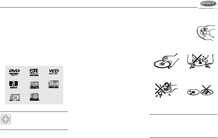
Disc Maintenance
Before playing, wipe the disc using a clean cloth, working from the center hole towards the outside edge.
Never use benzene, thinners,
cleaning fluids, anti-static liquids or any solvent.
|
|
|
Insert label |
Do not bend. |
|
side up. |
|
|
Never touch |
Wipe clean from |
the under side |
the center to the |
of the disc. |
edge. |
NOTE: A disc may become scratched (although not enough to make it unusable) depending on how you handle it and other conditions in the usage environment. These scratches are not an indication of a problem with the player.
3
JDV8035
INSTALLATION INSTRUCTIONS
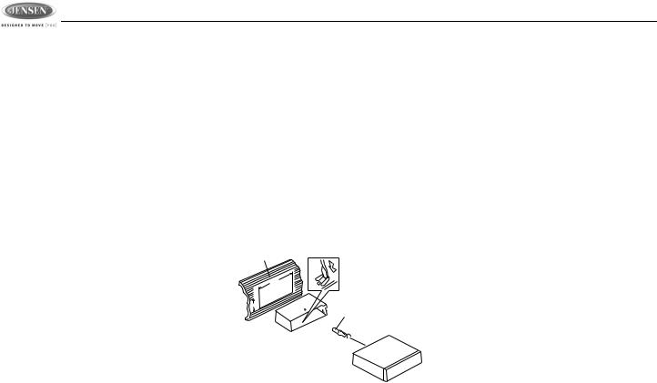
Before You Begin
1.Disconnect battery negative terminal.
2.Remove transport screws.
Important Notes
•Before final installation, test the wiring connections to make sure the unit is connected properly and the system works.
•Use only the parts included with the unit to ensure proper installation. The use of unauthorized parts can cause malfunctions.
•Consult with your nearest dealer if installation requires the drilling of holes or other modifications to your vehicle.
•Install the unit where it does not interfere with driving and cannot injure passengers if there is a sudden or emergency stop.
•If the installation angle exceeds 30º from horizontal, the unit might not give optimum performance.
•Avoid installing the unit where it will be subject to high temperatures from direct sunlight, hot air, or from a heater, or where it would be subject to excessive dust, dirt or vibration.
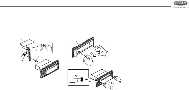
DIN Front Mount (Method A)
1.Slide the mounting sleeve off of the chassis if it has not already been removed. If it is locked into position, use the removal keys (supplied) to disengage it. The removal keys are depicted in “Removing the Unit”.
2.Check the dashboard opening size by sliding the mounting sleeve into it. If the opening is not large enough, carefully cut or file as necessary until the sleeve easily slides into the opening. Do not force the sleeve into the opening or cause it to bend or bow. Check that there will be sufficient space behind the dashboard for the radio chassis.
Dashboard
Bend Tabs
182
53
Screw Stud
3.Locate the series of bend tabs along the top, bottom and sides of the mounting
sleeve. With the sleeve fully inserted into the dashboard opening, bend as many of the tabs outward as necessary to firmly secure the sleeve to the dashboard.
4.Place the radio in front of the dashboard opening so the wiring can be brought through the mounting sleeve.
5.Follow the wiring diagram carefully and make certain all connections are secure and insulated with crimp connectors or electrical tape to ensure proper operation.
6.After completing the wiring connections, turn the unit on to confirm operation (vessel accessory switch must be on). If the unit does not operate, recheck all wiring until the problem is corrected. Once proper operation is achieved, turn the accessory switch off and proceed with final mounting of the chassis.
7.Carefully slide the radio into the mounting sleeve making sure it is right-side-up until it is fully seated and the spring clips lock it into place.
8.Attach one end of the perforated support strap (supplied) to the screw stud on the rear of the chassis using the hex nut and spring washer provided. Fasten the other end of the perforated strap to a secure part of the dashboard either above or below the radio using the screw and plain washer pro-
4
JDV8035
vided. Bend the strap, as necessary, to position it. CAUTION: The rear of the radio must be supported with the strap to prevent damage to the dashboard from the weight of the radio or improper operation due to vibration.
Dashboard
Support Strap
Plain Washer
Screw (4 x 12mm)
Screw Stud
Hex Nut (5mm)
Spring Washer
9.Test radio operation by referring to the operating instructions for the unit.
Trim Plate Installation
Push the trim plate against the chassis until it is fitted. You must do this before you install the control panel, otherwise it can't be attached.
Removing the Unit
To remove the radio after installation:
1.Insert fingers into the groove on the front of the frame and pull out to remove the frame
(when re-attaching, point the edge with the groove downward and attach).
2.Insert the removal keys straight back until they click, and then pull the radio out. If removal keys are inserted at an angle, they will not lock properly to release the unit.
Dashboard
Removal Key
5
|
|
JDV8035 |
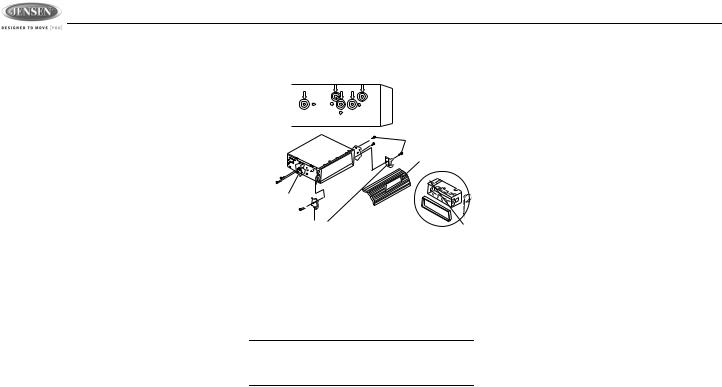
DIN Rear Mount (Method B) |
maximum screw size. Longer screws may |
Reconnect Battery |
This unit has threaded holes in the chassis side |
damage components inside the chassis. |
When wiring is complete, reconnect the battery |
|
||
panels which may be used with the original |
|
negative terminal. |
factory mounting brackets of some vehicles to |
|
|
mount the radio to the dashboard. Please |
|
|
consult with your local mobile stereo shop for |
|
|
assistance on this type of installation. |
Screws |
|
1. Remove the existing factory radio from the |
|
|
|
|
|
dashboard or center console mounting. |
Dashboard |
|
Save all hardware and brackets as they will |
|
|
be used to mount the new radio. |
Factory |
|
2. Carefully unsnap the plastic trim ring from |
|
|
Mounting |
|
|
the front of the new radio chassis. Remove |
Bracket |
|
and discard the trim ring. |
Hook (Remove) |
|
3. Remove the factory mounting brackets and |
|
|
hardware from the existing radio and attach |
4. Wire the new radio to the vehicle as out- |
|
them to the new radio. Select a position |
lined in the Universal Installation instruc- |
|
where the screw holes of the bracket and |
tions. |
|
the screw holes of the main unit are aligned |
5. Mount the new radio assembly to the dash- |
|
(are fitted). Tighten the screws at 2 places |
board or center console using the reverse |
|
on each side. Do not exceed M5 x 9 MM |
procedure of step 1. |
|
NOTE: The mounting box, outer trim ring, and half-sleeve are not used for method B installation.
6
JDV8035
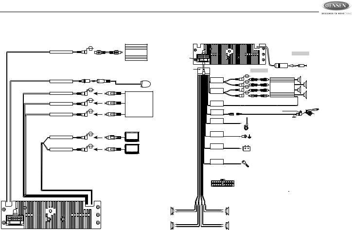
WIRING DIAGRAMS
Audio/Video Connections
SUB-WOOFER OUTPUT BLUE |
SUB |
|
SUB-W OUT |
||
WOOFER |
||
|
External Remote Sensor / Repeater Not Included
In This Packing. Sold Separately
EXTERNAL REMOTE JACK PINK |
EXTERNAL REMOTE |
|
REMOTE |
|
RECEIVER |
VIDEO INPUT |
YELLOW |
|
VIDEO IN |
|
|
AUDIO INPUT (RIGHT) |
RED |
VCR or DVD |
AUDIO IN R |
|
or |
|
|
GAME CONSOLE |
AUDIO INPUT (LEFT) |
WHITE |
|
AUDIO IN L |
|
|
VIDEO (1) OUTPUT |
YELLOW |
|
VIDEO OUT (1) |
|
|
VIDEO (2) OUTPUT |
YELLOW |
|
VIDEO OUT (2) |
|
|
FUSE
Electrical Connections
FUSE
20-PIN
AUDIO/POWER
HARNESS
(See Figure 1 )
LEFT FRONT
WHITE-BLACK LF
WHITE LF+
LEFT REAR
GREEN-BLACK LR
GREEN LR+
GREY
REAR
CHANNEL
BLACK
FRONT
CHANNEL
BLUE/WHITE
STRIPE
POWER
AMPLIFIER
REMOTE
PINK
PARKING
BRAKE ( )
)
BLUE
POWER ANTENNA/ AMPLIFIER REMOTE
BLACK
WHITE
CH-L
RED CH-R
WHITE
CH-L
RED CH-R
|
(Not supplied) |
ANTENNA |
ANTENNA |
EXTENDER |
|
JACK |
CABLE |
(Not supplied)
RCA-TO-RCA
CABLES
AMP
Connect to power amplifier, If not used,
Tape bare end of wire.
Brake Switch
Connect to Parking Brake.
Ground
Power Antenna
Connect to power antenna or amplifier,
If not used, Tape bare end of wire.
GROUND
YELLOW
+12 VOLTS CONSTANT
RED
+12 VOLTS SWITCHED
1 |
2 |
3 |
4 |
5 |
6 |
7 |
8 |
9 |
10 |
11 |
12 |
13 |
14 |
15 |
16 |
17 |
18 |
19 |
20 |
Pin View
RIGHT FRONT
GREY-BLACK RF
GREY RF+
RIGHT REAR
VIOLET-BLACK RR
VIOLET RR+
Ground
Connect to ground terminal or clean unpainted metal part of chassis.
Memory / Battery
Connect to battery or 12 volt power source that is always live. The radio will not work if this wire is not connected.
Accessory / Ignition
Connect to existing radio wire or radio fuse.
Figure 1 |
20 PIN AUDIO / POWER HARNESS |
|||
|
20 PIN HARNESS PIN CHART |
|
||
PIN |
WIRE COLOR |
|
FUNCTION / LABEL |
|
1 |
GREY / BLACK |
|
RIGHT FRONT SPEAKER ( |
) |
2 |
GREY |
|
RIGHT FRONT SPEAKER (+) |
|
3 |
VIOLET |
|
RIGHT REAR SPEAKER (+) |
|
4 |
VIOLET/BLACK |
|
RIGHT REAR SPEAKER ( |
) |
5 |
PINK |
|
PARKING BRAKE ( ) |
|
6 |
GREEN |
|
LEFT REAR SPEAKER (+) |
|
7 |
GREEN / BLACK |
|
LEFT REAR SPEAKER ( ) |
|
8 |
RED |
|
IGNITION (ACC) |
|
9 |
BLACK |
|
REAR PRE-AMPLIFIER LINE OUT COMMON |
|
10 |
RED |
|
RIGHT REAR PRE-AMPLIFIER LINE OUT |
|
11 |
WHITE |
|
LEFT FRONT SPEAKER (+) |
|
12 |
WHITE / BLACK |
|
LEFT FRONT SPEAKER ( |
) |
13 |
BLUE/WHITE |
|
POWER AMPLIFIER REMOTE (+) |
|
14 |
BLUE |
|
POWER ANTENNA |
|
15 |
YELLOW |
|
BATTERY (+) |
|
16 |
BLACK |
|
CHASSIS GROUND |
|
17 |
WHITE |
|
LEFT FRONT PRE-AMPLIFIER LINE OUT |
|
18 |
RED |
|
RIGHT FRONT PRE-AMPLIFIER LINE OUT |
|
19 |
BLACK |
|
FRONT PRE-AMPLIFIER LINE OUT COMMON |
|
20 |
WHITE |
|
LEFT REAR PRE-AMPLIFIER LINE OUT |
|
7
JDV8035
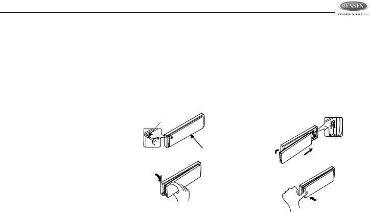
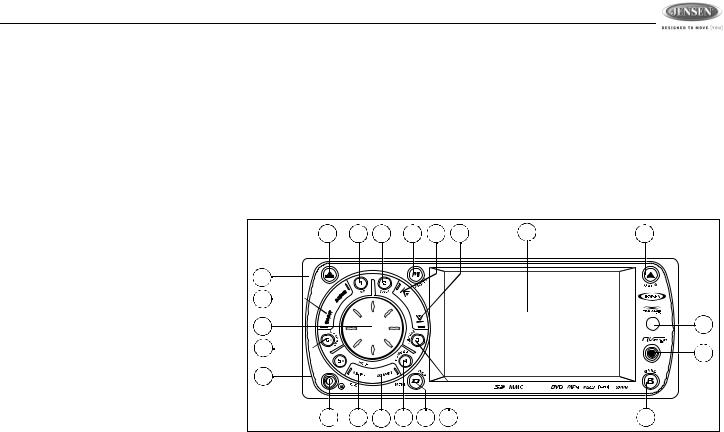
DETACHABLE CONTROL PANEL
•DO NOT insert the control panel from the left side. Doing so may damage it.
•Do not put pressure on the display or control buttons when handling the front panel.
•The rear connector that connects the main unit and the D.C.P is an extremely important part. Be careful not to damage it by pressing on it with fingernails, pens, screwdrivers, etc.
•If the D.C.P becomes dirty, wipe with a soft, dry cloth only. Use a cotton swab soaked in isopropyl alcohol to clean the socket on the back of the D.C.P.
•Make sure there is no dust or dirt on the electrical terminals on the back of the panel as this could cause intermittent operation or other malfunctions.
•The D.C.P can easily be damaged if dropped. After removing it, place it in a protective case and be careful not to drop it or subject it to strong shocks.
•When the release button is pressed and the D.C.P is unlocked, the car's vibrations may cause it to fall. To prevent damage to the D.C.P, always store it in a protective case after detaching it.
Removing the Control Panel
The front panel release button (3) releases the mechanism that holds the front panel to the chassis. To detach the front panel, perform the following steps:
1.Turn the power off.
2.Press the release button.
3.Grasp the left side to release the front panel and then pull it an an angle to remove the right side from the chassis.
Release
Button
Control Panel
Attaching the Control Panel
Before re-attaching the front panel, make sure the electrical terminals on the back of the panel are free of dust and dirt, as debris could cause intermittent operation or other malfunctions.
To attach the front panel:
1.Insert the right side of the control panel into the main unit, making sure the panel is attached at the T-joint (see diagram).
2.Push the left side of the control panel near the middle until a “click” sound is heard.
1.
2.
PUSH
8
JDV8035
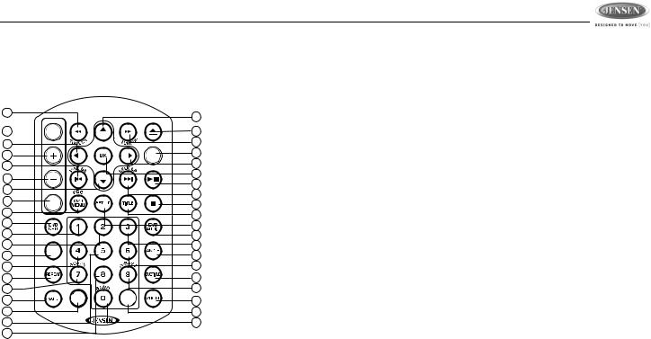
REMOTE CONTROL
The remote control will allow you to control the advanced functions of the JDV8035.
9
12
1 

10
5
15 VOLUME
6 |
|
|
|
13 |
|
|
|
3 |
AUDIO |
|
|
|
|
|
|
30 |
|
|
|
34 |
|
|
|
19 |
|
|
|
20 |
|
|
|
35 |
GOTO |
|
|
|
|
|
|
22 |
|
|
|
32 |
|
|
|
25 |
M |
E N |
U |
|
|||
7 |
DISPLAY |
||
|
|
|
|
40 |
|
|
|
23 |
|
|
|
26 |
|
|
|
|
|
2 |
|
|
8 |
|
MODE |
4 |
|
|
|
|
|
11 |
|
|
16 |
|
|
17 |
|
|
14 |
|
|
18 |
|
|
37 |
|
|
31 |
|
|
38 |
|
|
21 |
|
|
39 |
|
|
24 |
|
|
36 |
|
|
27 |
+10 |
|
33 |
|
|
|
|
|
29 |
|
|
28 |
1.Power
2.Open/Close/Eject
3.Audio Menu
4.Mode (select playing source)
5.Volume Up
6.Volume Down
7. |
Mute |
• |
Track Number Entry |
8. |
Tune Up/Fast Forward |
• |
File Number Entry |
9. |
Tune Down/Fast Reverse |
22. 4 |
|
10. |
Left |
• Tuner M4 recall, Memory 4 |
|
11. |
Right |
• |
Track Number Entry |
12. |
Up |
• |
File Number Entry |
13. |
Down |
23. 5 |
|
14. |
Seek Up |
• Tuner M5 recall, Memory 5 |
|
• |
Radio Tune |
• |
Track Number Entry |
• |
Track Up |
• |
File Number Entry |
• |
File Up |
24. 6 |
|
• |
Next |
• Tuner M6 recall, Memory 6 |
|
15. |
Seek Down |
• |
Track Number Entry |
• |
Radio Tune |
• |
File Number Entry |
• |
Track Down |
25. 7/SUB-W |
|
• |
File Down |
• |
Track Number Entry |
• |
Back |
• |
File Number Entry |
16. |
OK/Enter |
• |
Subwoofer ON/OFF |
17. |
Play/Pause |
26. 8 |
|
18. |
Stop/Return |
• |
Track Number Entry |
19. |
1 |
• |
File Number Entry |
• Tuner M1 recall, Memory 1 |
27. 9/iX-BASS |
||
• |
Track Number Entry |
• |
Track Number Entry |
• |
File Number Entry |
• |
File Number Entry |
20. |
2 |
• |
iX-Bass ON/OFF/Adjust |
• Tuner M2 recall, Memory 2 |
28. 0/BAND |
||
• |
Track Number Entry |
• |
Track Number Entry |
• |
File Number Entry |
• |
File Number Entry |
21. |
3 |
• Change Band (3 FM, 2 AM) |
|
•Tuner M3 recall, Memory 3
9
|
|
|
|
|
JDV8035 |
|
|
|
|
|
|
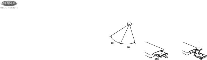
29. |
Press repeatedly to select a number in the |
Operating Range |
|
Replacing the Battery |
|
|
tens position for direct track entry (for |
The head unit remote |
REMOTE SENSOR |
When the range of operation of the card remote |
|
|
example, to select track “44”, press the +10 |
||||
|
control sensor (22) is |
|
control becomes short or stops functioning, |
||
|
button four times and then press the 4 but- |
located on the right side |
|
replace the battery with a new lithium battery. |
|
|
ton). |
of the control panel. |
|
Be sure to observe the proper polarity, as |
|
30. |
DVD MENU/PBC |
|
|||
The remote control can |
|
indicated below. |
|||
• |
DVD Menu |
|
|||
operate within a |
|
|
|||
• PBC (for VCD 2.0 and up) |
|
|
|||
distance of 3~5m of this |
|
(CR 2025) |
|||
31. |
SET UP Menu (Disc only) |
|
|
||
sensor. |
|
|
|||
32. |
REPEAT |
|
|
||
|
|
|
|||
33.ZOOM
34.DVD OSD (On Screen Display)
35. GOTO (direct entry) |
1 |
2 |
36.SUBTITLE (DVD)
37.DVD TITLE
38.DVD AUDIO
•DVD Audio
•VCD Audio L/R/ST
39.ANGLE (DVD only)
40.DISPLAY/MENU
10
JDV8035
OPERATING INSTRUCTIONS
Front Panel Open/Close
This unit is equipped with an advanced full logic motorized slide down front panel.
Press the OPEN button (8) to open the closed panel or to close the opened panel.
WARNING: Always use the OPEN button to open/close the front panel. Never try to open/close the front panel manually, as this will cause serious and permanent damage to the slide mechanism and void the warranty.
WARNING: Do not attempt to remove or attache the front panel (by pressing the detach button) when the panel is in the down (open) position. This may cause serious and permanent damage to the unit and panel. Only attach or detach the front panel when the panel is in the up (closed) position.
Power On/Off
Press and hold the  (power/mute) button (1) or short press any other button on the control panel (except open/eject) to turn the unit on.
Press and hold the power/mute button again to turn the unit off.
NOTE: It is a characteristic of LCD panels that, if subjected to cold temperatures for an extended period of time, they may take longer to illuminate than under normal conditions. In addition, the visibility of the numbers on the LCD may slightly decrease. The LCD read-out will return to normal when the temperature inside the vehicle increases to a normal range.
Volume Control
Turn the rotary encoder (4) to increase/ decrease the volume level, shown on display panel, from “00” to “46”. The display will automatically return to the normal indication 5 seconds after the last volume adjustment or when another function is activated.
Mute
Press the power/mute (  ) button (1) to mute the audio output “MUTE” appears on the display. Press the power/mute button again to restore audio output to the previous level.
Mode Selector (MODE)
Press this MODE button (9) to select a different mode of operation, as indicated on the display panel. Available modes include TUNER, DISC, CARD (SD), AV IN 1, AV IN 2.
AV IN/OUT Connector
Use the AV IN/OUT connector (21) to connect a portable media device for playback through the vehicle sound system.
1 Left Audio
2 Right Audio
3 Ground
4 Video
3.5mm A/V Cable ( not included )
See “AV Connector” on page 13 to learn how to reverse the AV IN/OUT connector from IN to OUT.
NOTE: For iPod or Zune video playback, please refer to owner's manual that came with your device. Please complete any photo or video setting adjustments before connecting the device to this unit.
11

JDV8035
Display Selector (D)
You can change the way playback information is displayed to suit your needs. Press the D/ DISP button (7) to alternate between the Image Display and Big Font Interface screens, shown below:
Image Display Interface
Big Font Interface
System Menu (D/MENU)
Press and hold the D/MENU button (7) for more than 3 seconds to display the system menu. You can then press the D/MENU button repeatedly or press the tune/track |||< or >||| buttons (18, 19) to access menu items.
Use the rotary encoder (4) to adjust the settings for a selected function. The display will return to the normal indication 5 seconds after the last adjustment or when another function is activated.
Angle
Turn the rotary encoder to adjust the angle of the front panel upward by choosing a setting from “00” to “12”.
Contrast
Turn the rotary encoder to adjust the screen contrast from “00” to “50”.
Bright
Turn the rotary encoder to adjust the screen brightness from “00” to “50”.
Color
Turn the rotary encoder to adjust the screen color level from “00” to “50”.
3 |
10 |
11 |
9 |
18 |
19 |
2 |
8 |
|
12 |
|
|
|
|
|
|
|
|
13 |
|
|
|
|
|
|
|
|
4 |
|
|
|
|
|
|
|
22 |
6 |
|
|
|
|
|
|
|
21 |
|
|
|
|
|
|
|
|
|
14 |
|
|
|
|
|
JDV8035 |
2 ZONE |
|
|
|
|
|
|
|
|
||
1 |
15 |
16 |
5 |
7 |
17 |
|
20 |
|
|
12 |
|
|
|
|
|
|
|

JDV8035
Date Set
Turn the rotary encoder to adjust the DATE/ MONTH/YEAR. Press the rotary encoder (4) to confirm each entry and move to the next field.
Clock
Turn the rotary encoder (4) to the right to adjust the minutes or to the left to adjust the hour.
Time Form
Turn the rotary encoder to adjust the clock format from “12 Hours” to “24 Hours”.
AV Connector
By default, the AV connector (21) on the front panel is designated as “IN”. Use the rotary encoder to change the source to “OUT”, allowing you to output the audio/video source from the built-in DVD player to another device.
Tuner Set (Local/Distant)
Turn the rotary encoder to choose “Local” or Distance”. Local mode favors access to local stations whose signals are much stronger.
Tuner Area
Turn the rotary encoder to choose the appropriate frequency spacing for your area: U.S.A., Latin, Europe, or Orit (Russia).
Beep Tone
Turn the rotary encoder to choose whether and audible beep is heard when a function is selected: “BEEP ON” or “BEEP OFF”.
Programmable Turn-On Volume (Vol PGM)
Turn the rotary encoder to select the default turn-on volume level. “VOL PGM 12” is the default setting.
Rear Speaker On/Off (Rear Spk)
Turn the rotary encoder to turn the rear speaker on/off. It is recommended to turn the rear speaker “OFF” when using headphones. When the rear speaker is “OFF”, the “FADER” audio function is disabled.
Internal Amplifier (Inter Amp)
Turn the rotary encoder to turn the system’s built in amplifier on/off. It is recomended to turn the internal amplifier “OFF” when connected to an external amplifier.
Audio Menu Button
Press the rotary encoder (4) repeatedly to access the Audio Menu functions, including sub-menu items. Use the tune/track |||< or >||| buttons (18, 19) to cycle through only the toplevel menu functions, and then press the rotary encoder to select the various adjustment options for that feature. Turn the rotary encoder to select settings for each option. The unit automatically exits audio control mode after five seconds of inactivity.
Sub-W
Only appears when subwoofer function is turned on. See “Subwoofer (SUB-W)” on page 15.
X-Bass
Only appears when X-Bass function is turned on. See “Bass Boost (iX-BASS)” on page 15.
BASS
To adjust Bass options, press the rotary encoder (4) until “BASS” appears in the display. Continue pressing the rotary encoder to access the following Bass settings:
•LEVEL
Turn the rotary encoder clockwise to increase or counter-clockwise to decrease the Bass level from “-6” to “+6”. “00” represents a flat response.
•Bass Center Frequency (C. Frq)
Turn the rotary encoder to adjust the Bass Center Frequency to 60, 80, 100 or 200Hz.
•Bass Quality Factor (BassQ)
Turn the rotary encoder to select one of the following Bass Quality Factor options: 2N, 1N, 1W, 2W. The following chart depicts the curve characteristics for each step:
13

JDV8035
Bass Quality Factor Curve Characteristics
Middle
To adjust Mid-Range options, press the rotary encoder (4) repeatedly until “Middle” appears in the display. Continue pressing the rotary encoder to access the following Mid-Range settings:
•LEVEL
Turn the rotary encoder clockwise to increase or counter-clockwise to decrease the Mid-Range level from “-6” to “+6”. “00” represents a flat response.
•Mid-Range Center Frequency (C.Frq)
Turn the rotary encoder to adjust the MidRange Center Frequency to 500Hz, 1KHz, 1.5KHz, or 2.5KHz.
•Mid-Range Quality Factor (BassQ)
Turn the rotary encoder to select one of the following Mid-Range Quality Factor options: 2N, 1N, 1W, 2W. The following
chart depicts the curve characteristics for each step:
Middle Quality Factor Curve Characteristics
Treble
To adjust Treble options, press the rotary encoder (4) repeatedly until “TREBLE” appears in the display. Continue pressing the rotary encoder to access the following Treble settings:
•LEVEL
Turn the rotary encoder clockwise to increase or counter-clockwise to decrease the Treble level from “-6” to “+6”. “00” represents a flat response.
•Treble Center Frequency (Freq)
Turn the rotary encoder clockwise to adjust the Treble Center Frequency to 10KHz, 12.5KHz, 15KHz or 17.5KHz.
3 |
10 |
11 |
9 |
18 |
19 |
2 |
8 |
|
12 |
|
|
|
|
|
|
|
|
13 |
|
|
|
|
|
|
|
|
4 |
|
|
|
|
|
|
|
22 |
6 |
|
|
|
|
|
|
|
21 |
|
|
|
|
|
|
|
|
|
14 |
|
|
|
|
|
JDV8035 |
2 ZONE |
|
|
|
|
|
|
|
|
||
1 |
15 |
16 |
5 |
7 |
17 |
|
20 |
|
|
14 |
|
|
|
|
|
|
|
JDV8035
Balance
To adjust the balance from “L12” (full left) to “R12” (full right), press the rotary encoder (4) until “Balance” appears in the display. Turn the rotary encode adjust the balance between the left and right speakers. “C00” represents a center balance.
Fader
To adjust the fader from “F12” (full front) to “R12” (full rear), press the rotary encoder (4) until “Fader” appears in the display. Turn the rotary encoder to adjust the fader between the front and rear speakers. “C00” represents a center fader level.
Subwoofer (SUB-W)
After connecting a subwoofer to the back of the unit, press the SUB-W button (13) to turn the subwoofer function “ON”. Press the rotary encoder to access and modify the following options:
•Level: Turn the rotary encoder to adjust the subwoofer Level from “00” to “12”.
•LPF: Turn the rotary encoder to adjust the LPF (Low Pass Filter) to 80Hz, 120Hz or 160Hz.
Bass Boost (iX-BASS)
When listening to music at low volume levels, this feature will boost the bass and treble ranges to compensate for the characteristics of human hearing. To turn iX-BASS on, press the
iX-BASS button (16) on the front panel and then use the rotary encoder to select “LOW”, “MID”, or “HIGH”. “XBAS” appears on the LCD. Press the IX-BASS button again to turn X-Bass off.
3 |
10 |
11 |
9 |
18 |
19 |
2 |
8 |
|
12 |
|
|
|
|
|
|
|
|
13 |
|
|
|
|
|
|
|
|
4 |
|
|
|
|
|
|
|
22 |
6 |
|
|
|
|
|
|
|
21 |
|
|
|
|
|
|
|
|
|
14 |
|
|
|
|
|
JDV8035 |
2 ZONE |
|
|
|
|
|
|
|
|
||
1 |
15 |
16 |
5 |
7 |
17 |
|
20 |
|
|
15 |
|
|
|
|
|
|
|

JDV8035
TUNER OPERATION
AM/FM Band Selector (BAND)
Press the B/BAND button (20) to change between three FM and two AM bands. Each band stores up to six preset stations.
Manual Tuning
Press the tune/track |||< button (18) to manually tune the radio station higher or press the tune/ track >||| button (19) to tune the radio station lower.
Seek Tuning
Press and hold the tune/track |||< button (18) to seek tune the radio station higher. Press and hold the tune/track >||| button (19) to seek tune the radio station lower.
Preset Stations
Up to six stations on each band can be stored as presets, which can then be instantly recalled by pressing the associated preset button (5, 6, 10, 11, 14, 17). To store a station, turn the radio on and select the desired band and station.
Press and hold a preset button (numbered one through six on the face of the radio) for more than two seconds. When stored, the preset number (CH1 - CH6) appears on the display. The station can now be recalled by pressing the corresponding preset button. Repeat for the
remaining five presets on the current band and for presets on the other four bands.
Preset Scan
Press the AS/PS button (15) to scan and play each preset station for 5 seconds each. Press AS/PS again to stop preset scan.
Automatic Preset Store
Press and hold the AS/PS button (15) to select six strong stations and store them in the current band using the AUTO PRESET feature. The radio will automatically scan the current band and enter strong stations into the preset memory positions. When using the AUTO PRESET feature, the new stations replace any stations already stored in preset memory.
NOTE: You can stop the AUTO PRESET function at any time by pressing the AS/PS button again.
Mono/Stereo Reception
During FM radio operation, the JDV8035 will automatically pickup a stereo signal, when available (“ST” appears on the display). When no stereo signal is available, the unit automatically reverts to mono operation.
16
JDV8035
DISC OPERATION
Insert Disc (OPEN)
Press the OPEN button (8) to open the front panel and reveal the disc slot. With the label surface facing up, gently insert the disc into the slot until the soft-loading mechanism engages and disc play begins. The front panel will close automatically and “Reading...” will appear on the screen while the disc loads.
NOTE: The unit is designed for play of standard 5” (12 cm.) compact discs only. Do not attempt to use 3” (8 cm.) CD singles in this unit, either with or without an adaptor, as damage to the player and/or the disc may occur. Such damage will not be covered by the warranty on this product.
Eject Disc (OPEN)
When the OPEN button (8) is pressed while a disc is inserted, disc play is stopped and the disc is ejected. The unit will revert to Tuner operation. If the disc is not removed from the unit within 15 seconds, the disc will be reloaded.
NOTE: To prevent a disc from accidentally being damaged, always remove the disc from the unit when disc play is finished.
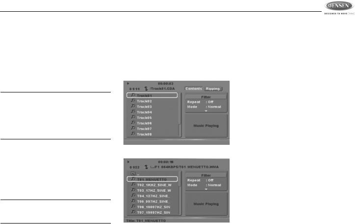
Controlling Playback
After inserting an audio disc, the player automatically plays the first track. The elapsed playing time is displayed at the top of the screen. The CD and MP3 user interfaces are shown below:
CD Audio Interface
MP3 Audio Interface
When the track is finished, the next track will play automatically. Press the 2/STOP button (11) to stop playback of the current file.
•Use the  ,
,  ,
,  or
or  buttons on the remote control to navigate the on-screen file list.
•Press the  button on the remote control or the 5 /\ button (14) on the control panel when the highlighted file is in the column on the far right to display the next ten files.
•Press the  button on the remote control or the 6 \/ button (6) on the control panel when the highlighted file is in the column to the far left to display the previous ten files.
•Press OK when a file number is highlighted or after numeric input to begin playback of the selected file.
•Use the remote control numeric buttons (0- 9, +10) to enter and play a file number directly. Press the +10 button repeatedly to select a number in the tens position for direct track entry (for example, to select track “44”, press the +10 button four times and then press the 4 button).
Disc Play/Pause
Press the 1/PAUSE button (10) to freeze disc play. Press 1/PAUSE again to resume disc play.
17
 Loading...