


JBR550
AM/FM/CD AUDIO SYSTEM with PA
Installation and Operation Manual

JBR550
CONTENTS |
|
System Features ................................................................................................. |
1 |
Safety Information .............................................................................................. |
2 |
Installation........................................................................................................... |
3 |
Basic Operation .................................................................................................. |
6 |
Tuner Operation.................................................................................................. |
8 |
CD Player Operation........................................................................................... |
9 |
Care and Maintenance...................................................................................... |
10 |
Troubleshooting................................................................................................ |
10 |
Specifications ................................................................................................... |
11 |
ii
JBR550
SYSTEM FEATURES
Features of the Jensen JBR550 mobile audio system include:
•AM/FM Tuner with 30 Presets (12 AM, 18 FM)
•Single In-Dash CD Player
•Public Announcement (PA) Feature with Optional Microphone (sold separately)
•Mute
•Electronic Bass, Treble, Balance and Fader Controls
•Clock
Content List
•Jensen Main Chassis
•Hardware Kit
•Wiring Harnesses (4-pin and 9-pin)
•Installation Manual
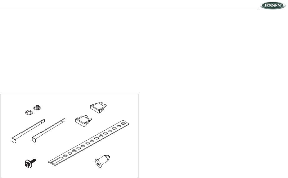
Hardware Kit
FLANGE NUTS |
1 AMP |
|
|
|
10 AMP |
DIN SLEEVE |
MOUNTING STRAP |
|
|
REMOVAL TOOL |
|
MOUNTING SCREW |
MOUNTING BUSHING |
1
JBR550
SAFETY INFORMATION
When Driving
Keep the volume level Iow enough to be aware of the road and traffic conditions.
When Washing your Vehicle
Do not expose the product to water or excessive moisture. Moisture can cause electrical shorts, fire or other damage.
When Parked
Parking in direct sunlight can produce very high temperatures inside your vehicle. Give the interior a chance to cool down before starting playback.
Use the Proper Power Supply
This product is designed to operate with a 12 volt DC negative ground battery system.
Protect the Disc Mechanism
Avoid inserting any foreign objects into the disc slot. Misuse may cause malfunction or permanent damage due to the precise mechanism of this unit.
CAUTION:
THIS MOBILE CD PLAYER IS A CLASS I LASER PRODUCT. THIS UNIT USES A VISIBLE/ INVISIBLE LASER BEAM WHICH COULD CAUSE HAZARDOUS RADIATION IF EXPOSED DIRECTLY. BE SURE TO OPERATE THE MOBILE CD PLAYER AS INSTRUCTED.
USE OF CONTROLS OR ADJUSTMENTS, OR PERFORMANCE OR PROCEDURES OTHER THAN THOSE SPECIFIED HEREIN MAY RESULT IN HAZARDOUS RADIATION EXPOSURE.
DO NOT OPEN COVERS AND DO NOT REPAIR BY YOURSELF. PLEASE REFER SERVICING TO A QUALIFIED TECHNICIAN.
WARNING:
Disc Maintenance
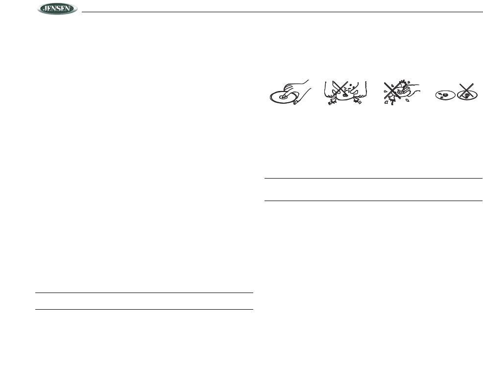
•A dirty or defective disc may cause sound dropouts while playing. Before playing, wipe the disc using a clean cloth, working from the center hole towards the outside edge. Never use benzene, thinners, cleaning fluids, anti-static liquids or any other solvent.
|
|
|
|
|
|
|
|
|
|
Insert label |
Do not bend. |
Never touch |
Wipe clean from |
|
side up. |
|
|
the under side |
the center to the |
|
|
|
of the disc. |
edge. |
|
|
|
|
|
•Be sure to use only round CDs for this unit and do not use any special shape CDs. Use of special shape CDs may cause the unit to malfunction.
•Do not stick paper or tape on the disc. Do not use CDs with labels or stickers attached or that have sticky residue from removed stickers.
•Do not expose discs to direct sunlight or heat sources.
NOTE: A disc may become scratched (although not enough to make it unusable) depending on how you handle it and other conditions in the usage environment. These scratches are not an indication of a problem with the player.
•TO REDUCE THE RISK OF FIRE OR ELECTRIC SHOCK, DO NOT EXPOSE THIS EQUIPMENT TO RAIN OR MOISTURE.
•TO REDUCE THE RISK OF FIRE OR ELECTRIC SHOCK AND ANNOYING INTERFERENCE, USE ONLY THE RECOMMENDED ACCESSORIES.
DISC NOTES
Depending on the recording status, conditions of the disc, and the equipment used for recording, some CD-Rs/CD-RWs may not play on this unit. For more reliable playback, please adhere to the following recommendations:
•Use CD-RWs with speed 1x to 4x and write with speed 1x to 2x.
•Use CD-Rs with speed 1x to 8x and write with speed 1x to 2x.
•Do not play a CD-RW which has been written more than 5 times.
NOTE: CD-R and CD-RW discs will not play unless the recording session is closed and the CD is finalized.
2

JBR550
INSTALLATION
Before You Begin
1.Disconnect Battery
Before you begin, always disconnect the battery negative terminal.
2.Remove Transport Screws
Important Notes
•Before final installation, test the wiring connections to make sure the unit is connected properly and the system works.
•Use only the parts included with the unit to ensure proper installation. The use of unauthorized parts can cause malfunctions.
•Consult with your nearest dealer if installation requires the drilling of holes or other modifications to your vehicle.
•Install the unit where it does not interfere with driving and cannot injure passengers if there is a sudden or emergency stop.
•If the installation angle exceeds 30º from horizontal, the unit may not give optimum performance.
•Avoid installing the unit where it will be subject to high temperatures from direct sunlight, hot air, or from a heater, or where it would be subject to excessive dust, dirt or vibration.
DIN Radio Installation
This unit is designed for installation in vehicle cabs with an existing 1-DIN radio opening. In many cases, a special installation kit will be required to mount the radio to the dashboard. These kits are available at electronics supply stores and car stereo specialty shops. Always check the kit application before purchasing to make sure the kit works with your vehicle.
to a secure part of the dashboard, either above or below the radio using the screw and flange nut provided. Bend the strap to position it as necessary.
CAUTION: The rear of the radio must be supported with either the perforated strap or the rubber mounting bushing to prevent damage to the dashboard from the weight of the radio or improper operation due to vibration.
PERFORATED SUPPORT STRAP
SECURE THIS END TO
REAR OF RADIO
DIN MOUNTING SLEEVE
LOCKING TABS 
REAR SUPPORT SCREW
SECURE THIS END TO SUB-DASH STRUCTURE
REMOVAL KEYS
MOUNTING SURFACE OPENING
NOTE: IF OPENING DOES NOT EXIST,
USE MOUNTING SLEEVE AS A TEMPLATE
AND CUT OPENING. FILE EDGES TO FIT
IF NECESSARY. DO NOT OVER FILE.
Universal Installation (Using Mounting Sleeve)
1.Slide the mounting sleeve off of the chassis. If it is locked into position, use the removal keys (supplied) to disengage it.
2.Check the dashboard opening size by sliding the mounting sleeve into it. If the opening is not large enough, carefully cut or file as necessary until the sleeve slides easily into the opening. Do not force the sleeve into the opening or cause it to bend or bow. Check that there will be sufficient space behind the dashboard for the radio chassis. Connect wires prior to actually installing the sleeve. Pigtail wiring should take place after hole size is confirmed. Mount sleeve after wiring.
3.Follow the wiring diagram carefully and make certain all connections of the wiring harness are properly secured and insulated to insure proper operation of this unit. After completing the wiring connections, turn the unit on to confirm operation (ignition switch must be “on”). If unit does not operate, recheck all wiring until the problem is corrected. Once proper operation is achieved, turn off ignition switch and proceed with final mounting of the chassis.
4.Locate the series of bend tabs along the top, bottom, and sides of the mounting sleeve. With the sleeve fully inserted into the dash opening, bend tabs outward so that the sleeve is firmly secured to the dashboard.
5.Carefully slide the radio into the mounting sleeve making sure it is right side up until it is fully seated and the spring clips lock it into place.
6.Attach one end of the perforated mounting strap (supplied) to the screw stud on the rear of the chassis using the flange nut provided. Fasten the other end of the perforated strap
Kit Installation
1.If your radio requires the use of an installation kit to mount this radio, follow the instructions included in the kit to attach the radio to the mounting plate supplied with the kit.
2.Wire and test the radio as described.
3.Install the radio/mounting plate assembly to the sub-dash according to the instructions of the installation kit.
4.Attach the support strap to the radio and dashboard as described above.
5.Replace the dashboard trim panel.
MOUNTING TAB DETAILS
CUTAW AY VIEW OF |
TOP TAB BEND |
SIDE VIEW |
MOUNTING SURFACE |
||
|
UPW ARD 90° |
MOUNTING |
|
|
|
|
MOUNTING |
SURFACE |
|
|
|
|
SLEEVE |
|
BEND TABS |
|
|
|
BOTTOM TAB |
|
|
BEND DOWNW ARD 90° |
|
3
 Loading...