


CD6112

CD6112
TABLE OF CONTENTS |
|
Table of Contents ...................................................................................... |
i |
Introduction .............................................................................................. |
1 |
Installation ................................................................................................ |
2 |
Wiring Diagram ........................................................................................ |
4 |
Front Panel Release ................................................................................ |
5 |
Operation ................................................................................................. |
6 |
Tuner Operation ....................................................................................... |
8 |
CD Player Operation ................................................................................ |
9 |
Remote Control ...................................................................................... |
10 |
Care and Maintenance ........................................................................... |
11 |
Troubleshooting ..................................................................................... |
12 |
Specifications ......................................................................................... |
13 |
i

CD6112
ii

CD6112
INTRODUCTION
Congratulations on your purchase of the Jensen CD6112 Mobile Receiver. It’s a good idea to read all of the instructions before beginning the installation. We recommend having your Jensen CD6112 installed by a reputable installation shop.
Features
CD
•CD R / RW Compatible
•Last Position Memory
•Audible Forward / Reverse Track Search
•Random, Repeat and Intro
•Play, Pause, Stop, Next Track and Previous Track
AM-FM
•USA / Europe Frequency Spacing
•30 Station Presets (18 FM / 12 AM)
•Stereo / Mono
•Local / Distance
•Auto Store / Preview Scan
Chassis
•Detachable Faceplate
•1.0 DIN (Import / ISO-DIN Mountable)
•8 Character / Segment Type LCD Display
•Chassis Mounted Rear Auxiliary Inputs
General
•Infrared Remote Control
•Media Adapter Cable (2 meter male 3.5mm to male RCA cable)
•Programmable Volume Control
•Three Preset EQ Curves
•Loudness
•Rotary Encoder Audio Control
•Beep Tone Confirmation (On-OFF Option)
•Rear Line Output
•200-Ohm Preamp Line Outputs
•2VRMS Line Outputs
1
INSTALLATION
This unit is designed for installation in cars, trucks and vans with an existing radio opening. In many cases, a special installation kit will be required to mount the radio to the dashboard. These kits are available at electronics supply stores and car stereo specialty shops. Always check the kit application before purchasing to make sure the kit works with your vehicle. If you have trouble locating a kit or need installation assistance, contact Technical Support at 1-800-323-4815 from 9:00am to 6:00pm EST Monday through Friday.
Tools and Supplies
The following tools and supplies are needed to install the radio:
•Torx type, flathead and Philips screwdrivers
•Wire cutters and strippers
•Tools to remove existing radio (screwdriver, socket wrench set or other tools)
•Electrical tape
•Crimping tool
•Volt meter/test light
•Crimp connections
•18 gauge wire for power connections
•16-18 gauge speaker wire
Preparation
1.Disconnect Battery
Before you begin, always disconnect the battery negative terminal.
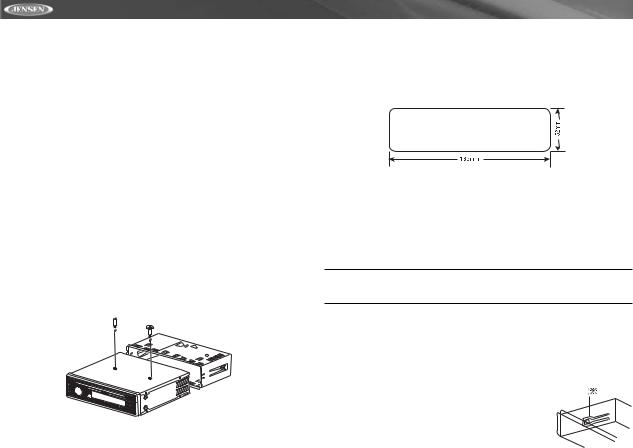
2.Remove Transport Screws
TRANSPORT 
SCREWS
HALF
SLEEVE
CD6112
3.Remove Radio from Sleeve
Lift latches on both sides of sleeve to remove half-sleeve from radio.
CD6112
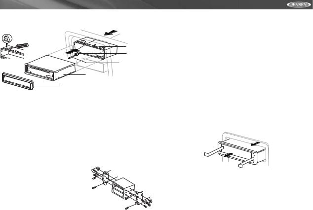
Using the Mounting Sleeve
1.Slide the mounting sleeve off the chassis. If it is locked into position, use the removal tools (supplied) to disengage it.
2.Check the dashboard opening size by sliding the mounting sleeve into it.
If the opening is too small, carefully cut or file as necessary until the sleeve easily slides into the opening. Do not force the sleeve into the opening or cause it to bend or bow. Check for sufficient space behind the dashboard for the radio chassis.
3.Locate the series of bend tabs along the top, bottom, and sides of the mounting sleeve. With the sleeve fully inserted into the dashboard opening, bend as many of the tabs outward as necessary to firmly secure the sleeve to the dashboard.
CAUTION: For proper operation of the CD player, the chassis must be mounted within 20° of horizontal. Make sure the unit is mounted within this limitation.
4. Place the radio in front of the dashboard opening so the wiring can be brought through the mounting sleeve. Follow the wiring diagram carefully and make certain all connections are secure and insulated with wire nuts or electrical tape. See “Wiring Diagram” on page 4.After completing the wiring connections, turn the unit on to confirm operation (vehicle ignition must be on). If the unit does not operate, re-check all wiring until the problem is corrected.
5. Make sure the radio is right-side up, then
carefully slide the radio into the mounting sleeve until it is fully seated and the spring clips
lock it into place.
6.Secure the rear of the unit to the car body using the mounting bolt and rubber cushion.
2
CD6112
7.Test the radio using the Operating Instructions that follow.
BEND TABS
MOUNTING
SLEEVE
RUBBER
CUSHION
MOUNTING BOLT
RADIO
TRIM RING
Kit Installation
If your vehicle requires the use of an installation kit to mount this radio, follow the instructions included with the installation kit to attach the radio to the mounting plate supplied with the kit.
1.Wire and test the radio as outlined in the Universal Installation instructions.
2.Install the radio/mounting plate assembly to the sub-dashboard according to the instructions in the installation kit.
3.Attach the support strap to the radio and dashboard as described in the Universal Installation instructions.
4.Replace the dashboard trim panel.
ISO Installation
This unit has threaded holes in the chassis side panels which may be used with the original factory mounting brackets of some vehicles to mount the radio to the dashboard. Please consult with your local
car stereo shop for assistance on this type of installation.
1. Remove the existing factory radio from the dashboard or center console mounting. Save all hardware and
brackets as they will be used to mount the new radio.
2.Carefully unsnap the plastic frame from the front of the new radio chassis. Remove and discard the frame.
3.Remove the factory mounting brackets and hardware from the existing radio and attach them to the new radio. Do not exceed M5 x 9 MM maximum screw size. Longer screws may damage components inside the chassis.
4.Wire the new radio to the vehicle as outlined in the Universal Installation instructions.
5.Mount the new radio assembly to the dashboard or center console using the reverse procedure of step 1.
Fuses
When replacing a fuse, make sure the new fuse is the correct type and amperage. Using an incorrect fuse could damage the radio.
Reconnect Battery
When wiring is complete, reconnect the battery negative terminal.
Removing the Radio
To remove the radio after installation, remove the trim ring by lifting in the center and pulling it off from either side. Insert the removal keys straight back until they lock, then pull the radio out. If removal keys are inserted at an angle, they will not lock properly and will not release the unit.
Technical Assistance
If you require assistance, contact Technical Support at 1-800-323-4815 from 9:00am to 6:00pm EST Monday through Friday.
3
CD6112
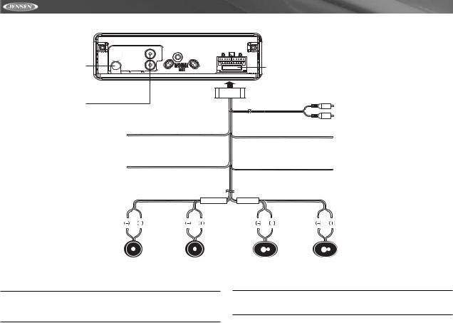
WIRING DIAGRAM
Antenna
Connect the antenna plug from the existing antenna cable (some vehicles require an adaptor).
R (Red)
L (White)
Aux-in |
Fuse (15 amp fast blow ATO)
Rear Line out |
R (Red) |
Gray |
L (White) |
Ground |
Black |
Connect to ground terminal |
|
or clean, unpainted part |
|
of chassis. |
|
Memory/Battery |
Yellow |
Connect to battery or 12 volt |
|
power source that is always live. |
|
The radio will not work if this |
|
wire is not connected. |
|
Blue |
Power Antenna |
|
Connect to power antenna or amplifier. |
||
|
||
|
If not used, tape bare end of wire. |
Red |
Accessory/Ignition |
|
Connect to existing radio wire |
|
or radio fuse. |
|
|
FRONT SP |
REAR SP |
|
|
White/Black |
White Gray/Black |
Gray |
Green/Black |
Green Purple/Black |
Purple |
Stripe |
Stripe |
|
Stripe |
Stripe |
|
Left Speaker |
Right Speaker |
Left Speaker |
Right Speaker |
(Front) |
(Front) |
(Rear) |
(Rear) |
NOTE: The amplifier in this radio is only designed for use with four speakers. Never combine (bridge) outputs for use with two speakers. Never ground negative speaker leads to chassis ground. Failure to wire exactly as shown may cause electrical damage to the radio.
NOTE: Only connect speakers rated in the load impedance of 4 ohms. Speakers with a load impedance less than 4 ohms could damage the unit.
4
 Loading...