


JRT199
Jenn-Air JRT199, JRTF1960, JRTF2160, JRTD229, JRT2160 User Manual
...
mJENN.AIR
Use & Care Manual
Frost Free Refrigerators
MODELSJRT1960,JRT2160,JRTD229,
JRT199,JRT219,JRTF1960,JRTF2160
I
Model JRTD229
Printed in U.S.A. PartNo._70304-1 Cat. No.STU1960UA
1996Jenn-Air 1/g6
Your Jenn-Air frost-free refrigerator was designed, engineered, and manufac-
tured to the highest standards of quality and performance. Since this manual
explains how you can obtain the best use of your Jenn-Air, it is essential that
you follow the instructions carefully.
Should you have any questions about using your Jenn-Air appliance, write to
us. Be sureto provide the model number of your appliance. Jenn-Air Customer
Assistance, c/o Maytag Customer Service, PO Box 2370, Cleveland, TN
37320-2370.
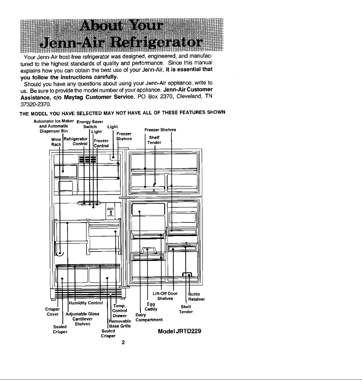
THE MODEL YOU NAVE SELECTED MAY NOT HAVE ALL OF THESE FEATURES SHOWN
Automatic Ice M_ker Energy Saver
and Automatic Switch Light
Dispenser Bin
RViinkRefrigernttr°;
Crisper Caddy
Cover Adjustable Glass Drawer Dairy Tender
Sealed
Crisper Sealed Model JRTD229
Crisper
Egg
Compartment
2
1. Use the three-pronged plug only with a grounding receptacle to provide protection
from electrical shock. This appliance must be installed in accordance with the
installation and grounding instructions on page 4-5.
2. Unplug your refrigerator before cleaning condenser, replacing a light bulb, or
making any repairs. Any servicing shouLdbe performed by a qualified technician.
3. Lncaseof powerfailure, minimize door openings. Ifpowerfailure is oflong duration,
protectfrozenfood byplacing blocksofdry iceon top ofthe packages, or check with
alocal frozenfoods locker plant abouttemporary storage. Frozenfoodswhich have
thawed completely should not be refrozen.
4. Any electric service cord that becomes frayed or damaged should be immediately
repaired or replaced. Never unplug your appliance by pulling on the power cord.
5. Your refrigerator should not be operated in the presence of explosive fumes.
6. Removethe doorsfrom anyout-of-use refrigerator to prevent child entrapmentand
suffocation.
7. DOnot place fingers or hands on the automatic ice making mechanismwhile the
refrigerator is plugged in. This will help protectyou from possible Lnjury. Ltwillalso
prevent interference with moving parts of the ejector mechanism and the heating
element that releases the cubes.
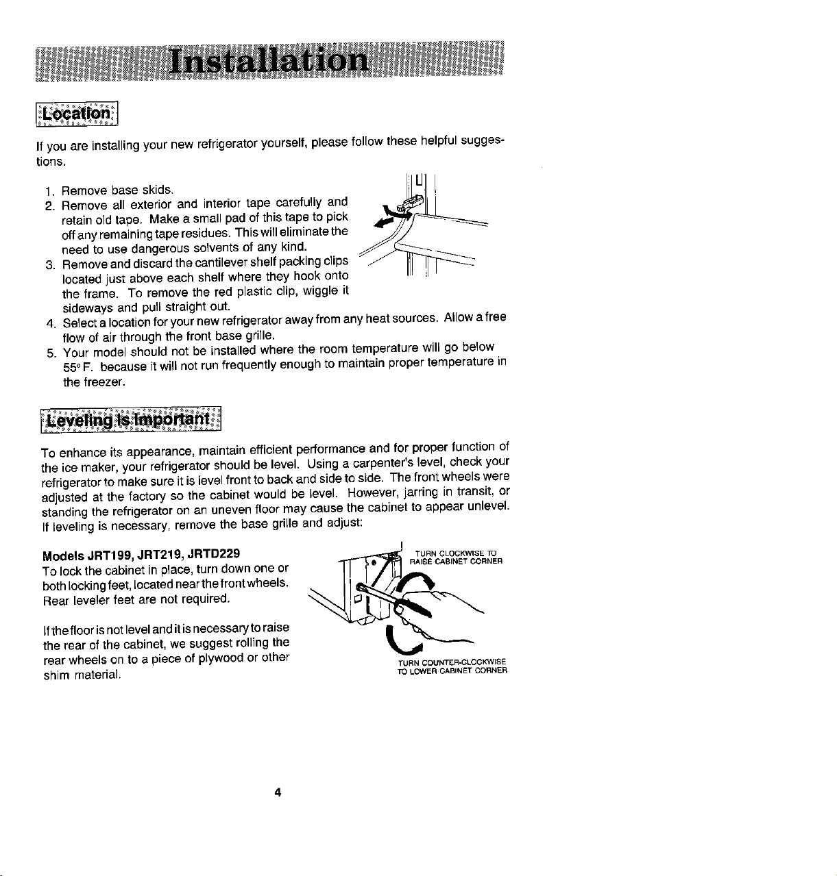
If you are installing your new refrigerator yourself, pleasefollow these helpful sugges-
tions.
1. Remove base skids, i I-J]L[-j I
2. Remove all exterior and interior tape carefully and ,, ,_ll
retainold tape. Makea small pad of this tape to pick
offany remainingtaperesidues. Thiswill eliminatethe
need to use dangerous Solventsof any kind.
3. Removeanddiscard thecantilevershelf packing clips
located just above each shelf where they hook onto
the frame. To remove the red plastic clip, wiggle it
sideways and pull straight out.
4. Select a locationforyour new refrigeratoraway from anyheatsources. Allow afree
flow of air through the front base grille.
5. Your model should not be installed where the room temperature will go below
55°,=. because Jtwillnotrun frequently enough to maintain proper temperature in
the freezer.
To enhance its appearance, maintain efficient performance and for properfunction of
the ice maker, your refrigerator should be level. Using a carpenter's level, check your
refrigerator to make sureit is levelfront to back and side to side. The front wheels were
adjusted at the factory so the cabinet would be level. However,jarring in transit, or
standing the refrigerator on an unevenfloor may cause the cabinet to appear unlevel.
If leveling is necessary, remove the base grille and adjust:
ModelsJRT199, JRT219, JRTD229 TUaNCLOCKWISETO
TOlock thecabinet in place, turn down one or I ._.
bothlockingfeet,located nearthefrontwheels.
r-,
Rear leveler feet are not required.
ifthe floorisnotlevelanditisnecessaryto raise xt_
the rear of the cabinet, we suggest rolling the
rear wheels on to a piece of plywood or other
shim material, To LOWER CABINET CORNER
RAISE CABINET CORNER
TURN COUNTER-CLOCKWISE
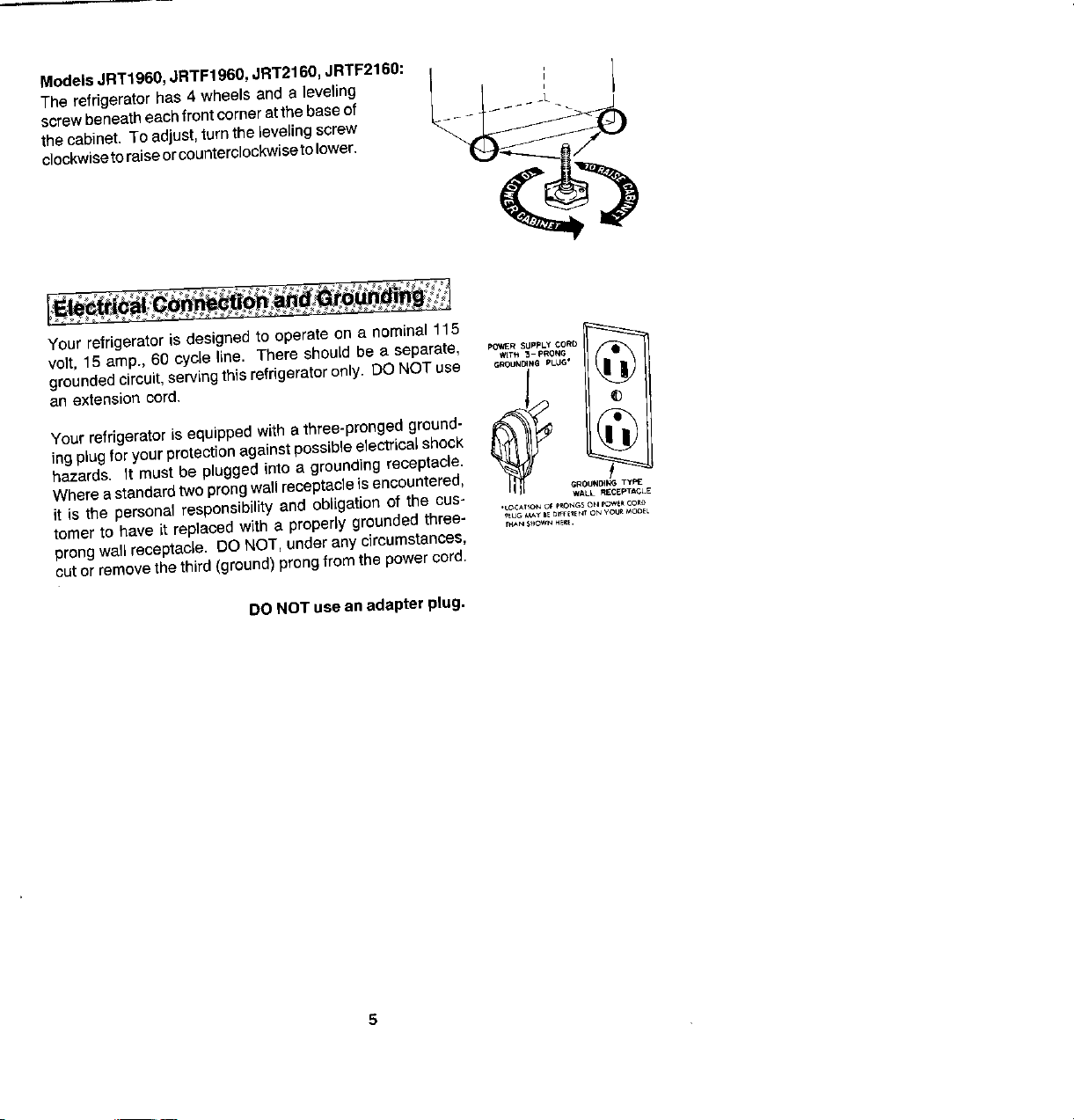
ModelsJRT1960,JRTF1960, JRT2160,JRTF2160: i _ I
The refrigerator has 4 wheels and a leveling I I , I
thecabinet. To adjust,turnthe leveling screw
clockwiseto raiseorcounterclockwisetolower.
screwbeneatheachfront corneratthe baseof _- _ _L
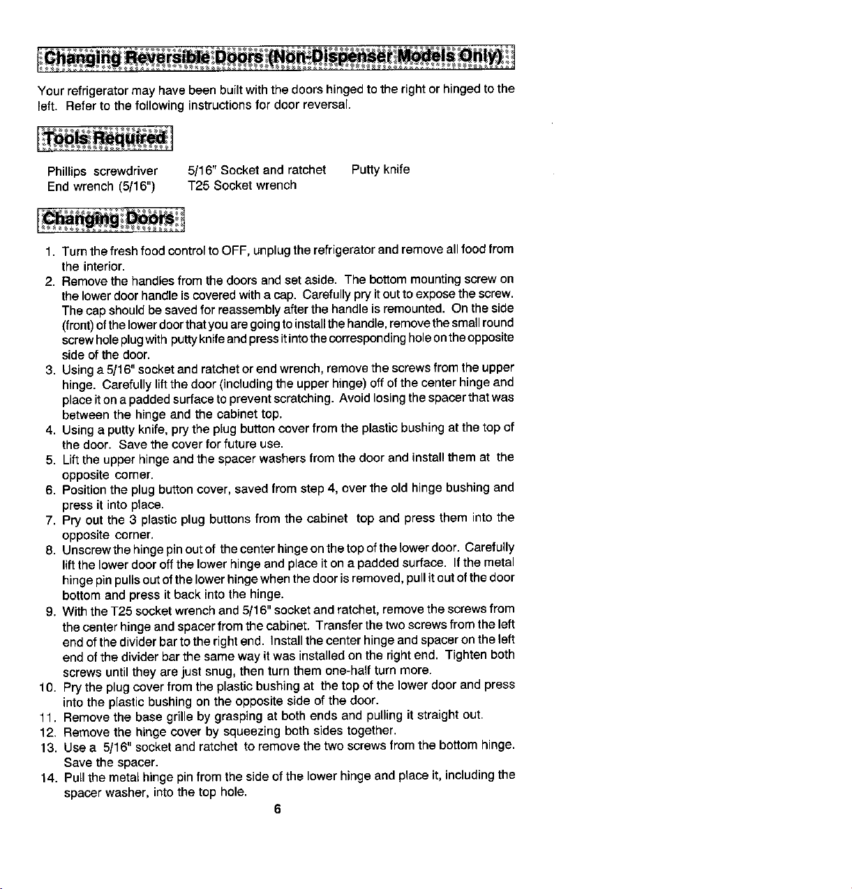
Your refrigerator is designed to operate on a nominal 115 _
volt, 15 amp., 60 cycle line. There should be a separate, ._t._-P.o.G •
grounded circuit, serving this refrigerator only, DO NOTuse _o,_,_ p_.
pQ_VER SUppLy CORO
ing plug for your protectionagainst possible electrical shock
hazards. It must be plugged into a grounding receptacle.
Where astandardtwo prongwaftreceptacleis encountered, _u.D,_ T_
Your refrigerator is equipped with a three-pronged ground-
it is the personal responsibility and obligation of the cue- WALL.ECE.'.CLE
tomer to have it replaced with a properly grounded three- ,,o_,_,_o.,E,_o_oo,_oo_
•LOCATIQN O_ p_NG $ OH pQV#_ _ORO
TH_,NS_WN HE_t.
prong wall receptacJe. DO NOT,under any circumstances,
cut or remove the third (ground) prong from the power cord.
DONOT usean adapter plug,
Your refrigerator may have been built with the doors hingedto the right or hinged to the
left. Refer to the following instructionsfor door reversal.
Phillips screwdriver 5/16'rSocket and ratchet Putty knife
End wrench (5/16") T25 Socket wrench
1. Turnthe fresh food control toOFF, unplugthe refrigerator end remove allfood from
the interior.
2. Removethe handlesfrom the doors and set aside. The bottom mounting screwon
thelowerdoor handleis coveredwitha cap. Carefullypry itout to exposethe screw.
Thecap shouldbe savedfor reassemblyafterthe handle is remounted. On the side
(front)ofthelowerdoorthat you aregoingtoinstallthe handle,removethe smallround
screwholeplugwith puttyknifeandpressit intothecorrespondingholeontheopposite
side of the door.
3. Usinga5/16" socket and ratchet or end wrench, remove thescrews from the upper
hinge. Carefully lift thedoor (includingthe upper hinge) off ofthe centerhinge and
placeitonapaddedsurface toprevent scratching. Avoidlosing the spacerthatwas
between the hinge and the cabinet top.
4. Usinga putty knife, pry the plug button cover from the plastic bushing at the top of
the door. Save the cover for future use.
5. Lift the upper hinge and the spacer washers from the door and install them at the
opposite corner.
6. Positionthe plug button cover, saved from step 4, overthe old hinge bushing and
press it into place.
7. Pry out the 3 plastic plug buttons from the cabinet top and press them into the
opposite corner.
8. Unscrewthehinge pinoutof the center hingeon thetopofthe lower door. Carefully
liftthe lower door off the lower hinge and place iton a padded surface. Ifthe metal
hingepinpullsoutofthe lowerhingewhen the door isremoved,pull itoutofthe door
bottom and press it back into the hinge.
9. With the T25 socket wrench and 5/16" socket and ratchet, remove thescrews from
the center hinge and spacerfrom thecabinet. Transferthe two screws from the left
endof the divider barto the rightend. Installthe center hingeand spacer on the left
end of the divider bar the same way itwas installed on the right end. Tighten both
screws until they are just snug, then turn them one-half turn more.
10. Prythe plugcover from the plastic bushing at the top of the lower door and press
into the plastic bushing on the opposite side of the door.
11. Remove the base grille by grasping at both ends and pullingit straight out.
12. Remove the hinge cover by squeezing both sidestogether.
13. Use a 5/16" socket and ratchet to remove the two screws from the bottom hinge.
Savethe spacer.
14. Pull the metal hinge pinfrom the side of the lower hinge and place it, includingthe
spacer washer, into the top hole.
6
15. Pryout the two screw hole plug buttons on the bottom left side of the top door and
lowerdoor. On some models, remove the door stops (metal plates) on the bottom
ofeachdoorandinstallthemon oppositesides. Pressintheplug buttonsinthe holes
on the right side of both doors.
16. Setthelower dooronthe bottomhinge,making surethe hinge pinentersthe bushing
in the door bottom.
17. While hoWtirtcjthe doer in a clesed positlen, take the canter hinge pin that was
removedin step 8 and screw itthrough the left holeof the center hinge and into the
bottomdoorbushing. Makesurethe longpingoes intothebottom doorandthe short
pin goes into the top door.
18. Setthe upper door on the center hinge, making sure the hinge pinenters the door
bushing. When you close the door, the gasket should hold it in place.
19. Making sureto usethe same number of spacersthat were originally used beneath
theupper hinge, installthe hinge mountingscrews. Beforetigbteningthesescrews,
make sure the top ofthe door is level with the cabinet top, and the space between
the door is equidistant acrossthe entire front. Avoidover-tightening these screws.
Tighten both untilthey are just snug, then turn them in another one-half turn.
20. Examine the door gasket all around each door, making sure no gaps are visible
betweenthegasketandcabinet. Ifagapshows, trystretchingthegasketaway#om
the door. The magnet will contact the cabinet surface.
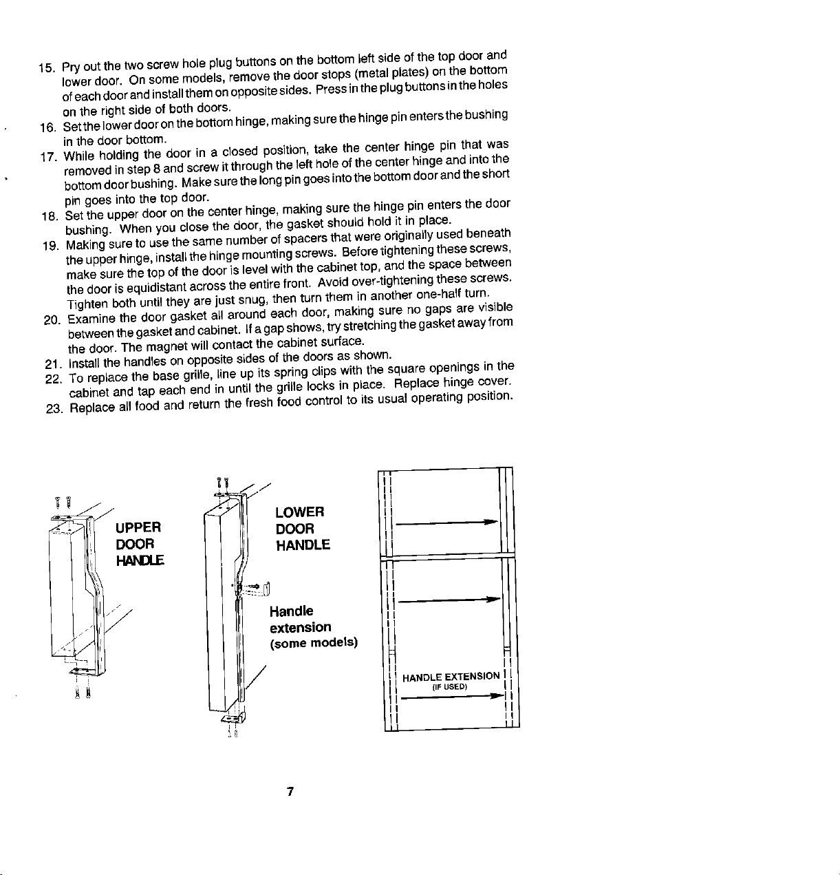
21. Insta}]the handles on oppositesides of the doors as shown.
22. To replace the base grille, line up its springclips with the square openings in the
cabinet and tap each end in until the grille locks in place. Replacehinge cover.
23. Replace all food and returnthe fresh food control to its usual operating position.
17 j./ " I
_ J _ 7 LOWER
..... UPPER DOOR =
DOOR HANDLE II
_J
n
Handle
. I extension
._,_ / (some models)
/
I HANDLE EXTENSION I
[IF USED)
 Loading...