


Professional 48 , 36 , 30 |
|
Gas Range Models |
403 WEST FOURTH STREET, NORTH NEWTON, IA 50208 |
Retain this manual for future reference.
(17663 Rev. B) |
8101P601-60 |
|
(05-04-03) |
30 GAS RANGE MODEL |
|
36 GAS RANGE MODEL |
MODEL PRG3010 |
|
MODEL PRG3610 |
|
|
|
48
MODEL PRG4810
2
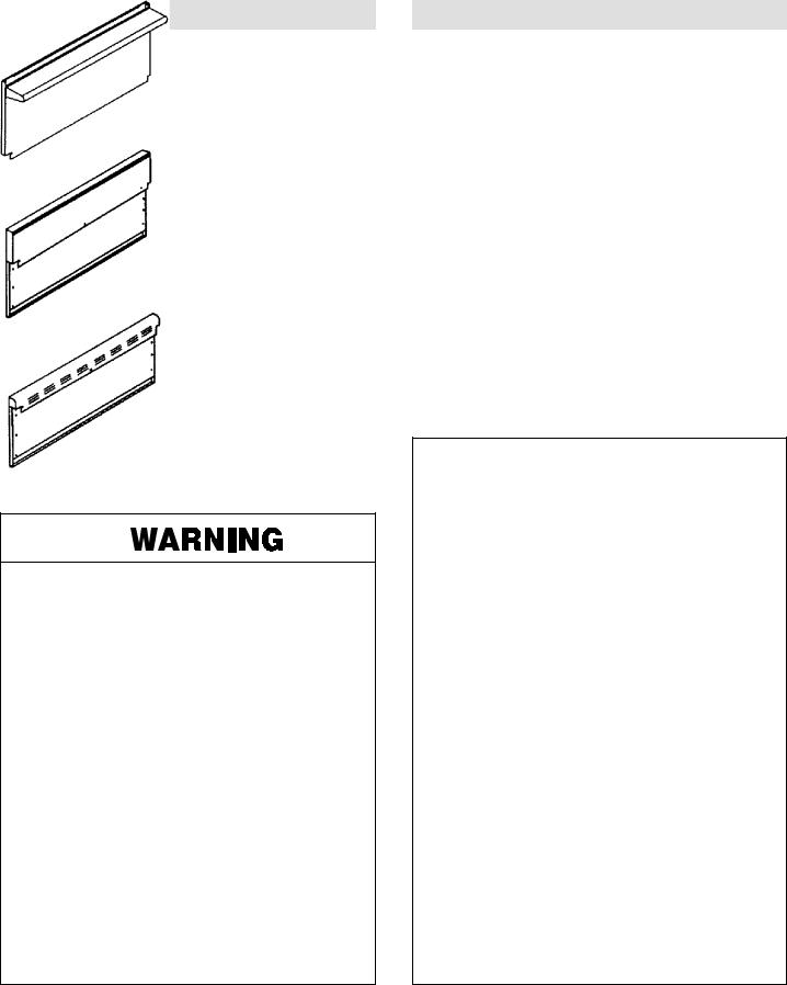
TABLE OF CONTENTS |
|
|
MODEL IDENTIFICATION . . . . . . . . . . . . . . . . . . |
. . . . . . 2 |
|
WARNING |
. . . . . . . . . . . . . . . . . . . . . . . . . . . . . . . . |
. . . . . . 3 |
INTRODUCTION . . . . . . . . . . . . . . . . . . . . . . . . . . . |
. . . . . . 3 |
|
IMPORTANT INSTALLATION INSTRUCTIONS . . . . . 4 |
||
STEP 1 - |
Ventilation Requirements . . . . . . . . . . |
. . . . . . 4 |
STEP 2 - |
Cabinet Preparation . . . . . . . . . . . . . . |
. . . . 5-6 |
STEP 3 - Unpacking, Moving And Placing |
|
|
|
The Range . . . . . . . . . . . . . . . . . . . . . . |
. . . . 7-8 |
GRIDDLE ADJUSTMENTS . . . . . . . . . . . . . . . . . |
. . . . . . 8 |
|
ANTI-TIP INSTALLATION INSTRUCTIONS . . . |
. . . . . . 9 |
|
STEP 4 - |
Electrical Connections . . . . . . . . . . . . |
. . . . . 10 |
STEP 5 - |
Gas Requirements . . . . . . . . . . . . . . |
10-11-12 |
STEP 6 - |
Backguard Installation . . . . . . . . . . . . |
. . . . . 12 |
STEP 7 - Test And Adjustment . . . . . . . . . . . . . |
. . 13-14 |
|
INSTALLER FINAL CHECK LIST . . . . . . . . . . . . |
. . . . . 14 |
|
WIRING DIAGRAM |
|
|
(PRG3010, PRG3610, PRG4810 Series) . . . . |
. . . . . 15 |
|
SCHEMATIC DIAGRAM |
|
|
(PRG3610, PRG4810, PRG3010 Series) . . . . |
. . . . . 16 |
|
If the information in this manual is not followed exactly, a fire or explosion may result, causing property damage, personal injury, or death.
Do not store or use gasoline or other flammable vapors and liquids in the vicinity of this or any other appliance.
WHAT TO DO IF YOU SMELL GAS:
S Do not try to light any appliance.
SDo not touch any electrical switch, do not use any phone in your building.
SImmediately call your gas supplier from a neighbor’s phone. Follow the gas supplier’s instruction.
SIf you cannot reach your gas supplier, call the fire department.
Installation and service must be performed by a qualified installer, service agency, or the gas supplier.
INTRODUCTION
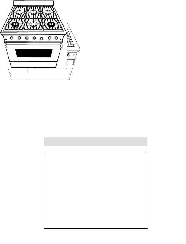
The features offered by the Jenn-Air professional series of gas ranges are certain to make the cooking experience more enjoyable and provide the novice or the experienced chef with years of enjoyment. A large capacity gas oven with a gas infrared broiler is included on the 30 , 36 and 48 ovens. The PRG4810 (48 ) range is also equipped with a smaller 12 oven that is perfect for baking breads and other small items while the larger items are being prepared in the large capacity convection oven. Model PRG3010 offers (4) 15,000 Btu/Hr. top burners, while the 36 and 48 models offer (6) 15,000 Btu/Hr. top burners. All ranges are equipped with dual flow simmer burners with a simmer turn down of 570-900 Btu/Hr, which can be used for melting butter or chocolates. Model PRG3010 offers one simmer burner, while models PRG3610 and PRG4810 offer two simmer burners each. In addition to the large capacity oven and high output top burners, the 48 range also offers a stainless steel griddle. All range models require installation of one of the three backguards (this piece must be ordered separately) except the PRG3010 model, which is shipped standard with a 9 low back. See Figure 1.
FIGURE 1
3

IMPORTANT INSTALLATION INSTRUCTIONS
Tested in accordance with ANSI Z21.1-1993 Standard for Household Cooking Gas Appliances.
These ranges must be installed in conjunction with a suitable overhead vent hood. (See Step: 1 for Ventilation Requirements). Due to the professional high heat capacity of this unit, particular attention should be paid to the hood and duct work installation to assure it meets local building codes. To eliminate risk of burns or fire by reaching over heated surface units, cabinet storage located above the surface units should be avoided.
Check local building codes for the proper method of range installation. Local codes vary. Installation, Electrical Connections, and Grounding must comply with all applicable codes. In the absence of local codes, the range should be installed in accordance with the National Fuel Gas Code ANSI Z223.1-Latest Edition and National Electrical Code ANSI / NFPA 70-Latest Edition.
Model numbers with suffix ‘NP’ are manufactured for use with natural gas, while model numbers with suffix ‘LP’ are for use with LP gas (propane).
STEP 1: VENTILATION REQUIREMENTS
A suitable exhaust hood must be installed above the range. The following chart indicates the minimum blower capacity recommended for hood ventilation. (Table 1).
CAUTION
Ventilation hoods and blowers are designed for use with single wall ducting. However, some local building codes or inspectors may require double wall ducting. Consult local building codes and/or local agencies, before starting, to assure that hood and duct installation will meet local requirements.
Hood blower speeds should be variable to reduce noise and loss of heated or air conditioned household air when maximum ventilation is not required.
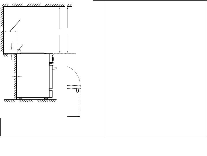
For best smoke elimination, the lower edge of the hood should be installed a minimum of 30 to a maximum of 36 above the range cooking surface, see figure 3. If the hood contains any combustible materials (i.e. a wood covering) it must be a minimum of 36 above the cooking surface.
Due to a high volume of ventilation air, a source of outside replacement air is recommended. This is particularly important for tightly sealed and insulated homes. A reputable heating and ventilating contractor should be consulted.
TABLE 1
VENTILATION UNIT |
STANDARD COUNTER INSTALLATION |
ISLAND INSTALLATION |
|
RECOMMENDATIONS |
RECOMMENDATIONS |
||
HOOD |
(24 Deep x Unit Width) |
(30 Deep x 36 At Bottom) |
|
BLOWER |
|
RANGE - 800-1000 CFM |
800-1000 CFM |
|
48 |
||
|
36 |
RANGE - 600-800 CFM |
600-800 CFM |
|
30 |
RANGE - 500 CFM |
500 CFM |
4
STEP 2: CABINET PREPARATION
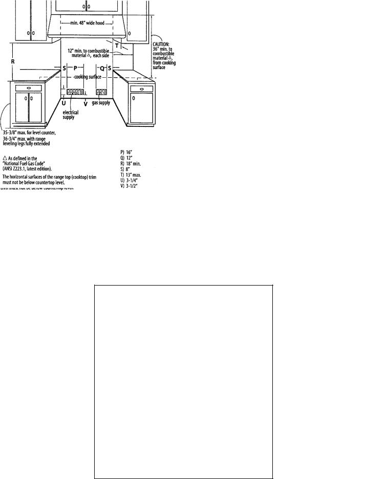
1.The range is a free-standing unit. If the unit is to be placed adjacent to cabinets, the clearances shown in Figures 2A/B/C are required. The same clearances apply to island installations.
2.The range can be placed in various positions with respect to the cabinet front, with the front either flush or projecting, depending on the countertop depth. See
Figure 3A/B and Table 2 (side view of range) for dimensions.
3.The gas and electrical supply should be within the zones shown in Figures 2 and 4.
4.The maximum depth of over head cabinets installed on either side of the hood is 13 .
(PRG3010) |
|
(PRG3610) |
|
|
|
(PRG4810)
5
5.Any openings in the wall behind the range and in the floor under the range must be sealed.
6.When there is less than a 12 clearance between combustible material and the back edge of the range, (above the cooking surface) Jenn-Air Stub Back or High Shelf Backguard must be installed. These parts must be ordered separately, except for the PRG3010 which comes equipped with a Low Back. Figure 3A
and Figure 3B indicate the space required for each type of backguard.
7.Always keep the appliance area clear and free from combustible materials, gasoline and other flammable vapors and liquids.
8.Do not obstruct the flow of combustion and ventilation air to the unit.
|
|
F |
|
|
12 Min. To Combustibles |
|
|
G |
|
|
|
|
|
|
|
Without Backguard |
|
|
|
|
|
|
|
|
|
High Shelf |
36 Min. To |
|
36 Min. To |
D |
|
H |
Combustibles |
|
Combustibles |
|
|
|
|
||
|
|
|
|
1-1/2 |
Island Trim |
|
C |
|
|
|
|
|
Low Back |
|
|
|
|
|
|
|
|
|
0 Clearance |
0 Clearance |
A |
|
E |
|
B |
|
FIGURE 3A |
FIGURE 3B |
TABLE 2
DIMENSIONS |
A |
B |
C |
D |
E |
F |
G |
H |
PRG4810 |
27-7/16 |
44-11/16 |
12 |
21-1/4 |
29-15/16 |
28-3/16 |
10 |
2-1/2 |
PRG3610 |
27-7/16 |
44-11/16 |
12 |
21-1/4 |
29-15/16 |
28-3/16 |
10 |
2-1/2 |
|
|
|
|
|
|
|
|
|
PRG3010 |
26-3/4 |
44-1/4 |
9 |
21-1/4 |
29-15/16 |
28-3/16 |
9-3/8 |
1-3/4 |
6
STEP 3: UNPACKING, MOVING AND PLACING THE RANGE
CAUTION
PROPER EQUIPMENT AND ADEQUATE MANPOWER MUST BE USED IN MOVING THE RANGE TO AVOID DAMAGE TO THE UNIT OR THE FLOOR. THE UNIT IS HEAVY AND RESTS ON ADJUSTABLE STEEL LEGS.
DO NOT LIFT THE RANGE BY THE
OVEN DOOR HANDLES!!
The 36 range has a shipping weight of approximately 408 pounds or 354 pounds after removal of packing materials. It is recommended that the door, grates, burners, front kick panel and drip pan (below knobs), be removed to facilitate handling. This will reduce the weight to about 230 pounds.
DO NOT REMOVE THE GRIDDLE
ASSEMBLY
It may be necessary to remove the oven door and knobs to pass through some doorways. With the doors and knobs removed a 29-3/8 wide opening is required. Without removing the door, a 30-13/16 wide opening is required. See Figure 3A.
Flex Line to Range
Manual Shut-Off
Valve must be
Easily Accessible
2 Maximum
Protrusion from Wall for Gas Supply
FIGURE 4
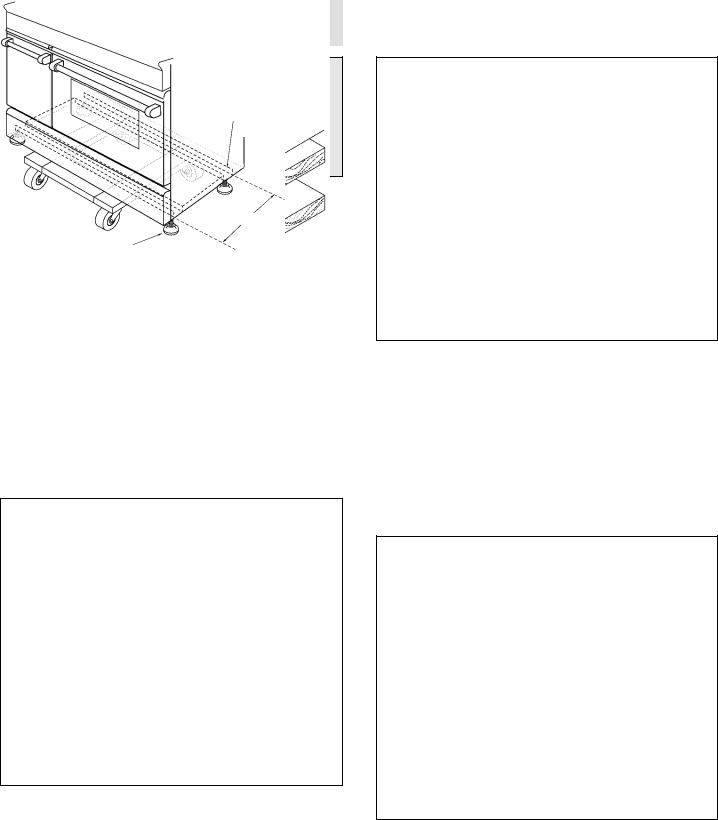
Kick Panel
FIGURE 5
Remove the outer carton and packing material from the shipping base. Remove the kick panel (see Figure 5) by removing two screws at the top and pulling forward. The range is held to the skid by two bolts in the front behind the kick panel (see Figure 5) and two L-brackets located on bottom flange of the range back (see Figure 7). After removing the bolts and brackets, the range must be lifted and removed from the skid. Due to the weight, a dolly with soft wheels should be used to move this unit. The weight must be supported uniformly across the bottom (see Figure 6).
Range Must be Uniformly Supported on Braces
Leveling Legs
FIGURE 6
7
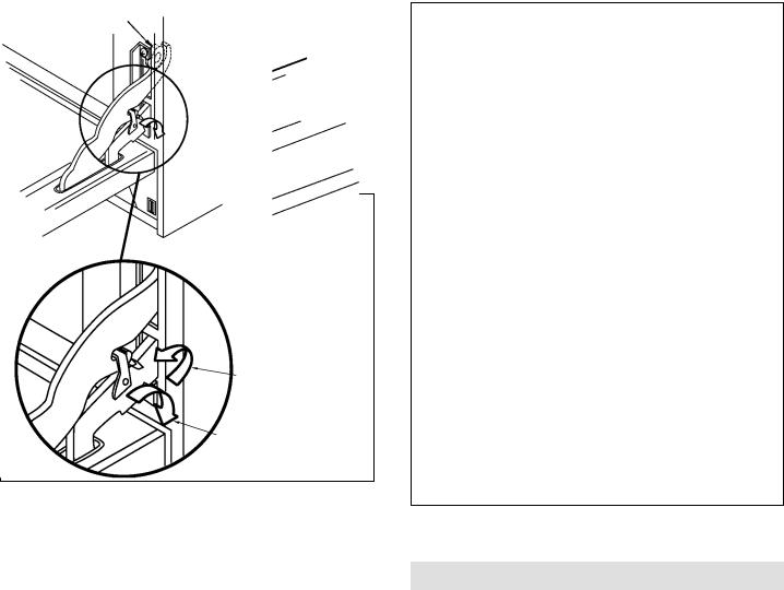
To remove the door, open the door and hold it all the way open. Close the hinge latches (see Figure 8) and release the door. The door can then be removed by gently lifting and pulling the door, with the hinges up and out of the frame. The hinges are assembled to the door and will be removed from the frame when the door is lifted upward.
The professional range should be transported by a dolly close to its final location. The range can be tipped back and supported on the rear legs while the dolly is removed.
The floor under the legs should be protected (Wood Strips, Carpet, Paneling, Etc.) before pushing the unit back into position. Electric and gas connections should be made (Steps 4 & 5) and the backguard installed (Step 6) before the range is placed in its final position.
Left Rear Shipping
Screws
FIGURE 7
For proper performance, the professional range should be level. To achieve a flush fit of the range to adjoining countertops, it will be necessary to have level cabinets (front to back, and left to right across the opening of the range). After checking the countertops for level and before sliding the range into place, measure the distance from the floor to the top of the counter work surface in the rear left and right corners. Adjust the corresponding rear corner of the range to an equal height of the counter, as the rear leveling legs are not accessible once the range is pushed into place. Once the range is in place, the front leg levelers can be accessed to level the front of the range. Replace the kick panel and oven doors by reversing the procedure described previously.
It is important that the two screws retaining the kick panel are secure to prevent accidental access to live electrical components and wires (see Figure 5).
Door Hinge Roller
Lock (Close)
Un-Lock
FIGURE 8
GRIDDLE ADJUSTMENTS
The griddle section is fastened in place at the front with screws. It is designed to be stationary and not meant to be removed for cleaning.
The griddle has two leveling screws beneath the rear flue cover which can be used to adjust the griddle to the desired slope. The center screw is for shipping and should be removed.
8
ANTI-TIP DEVICE INSTALLATION
INSTRUCTIONS
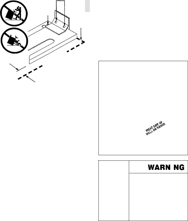
NOTE: A risk of range tip over exists if the appliance is not installed in accordance with the installation instructions provided. The proper use of this device minimizes the risk of TIP-OVER. In using the device the consumer must still observe the safety precautions as stated in the USE and CARE MANUAL and avoid using the oven door and/or kick plate as a step stool.
Installation instructions are provided for wood and cement in either floor or wall. Any other type of construction may require special installation techniques as deemed necessary to provide adequate fastening of the ANTI-TIP bracket to the floor or wall.
Included Parts
Included with this kit are: (4) #10 x 2 wood screws and
(1) Anti-tip bracket.
Wood Construction
Place the bracket against the back wall, into the right rear corner where the range is to be located. Leave a gap between the wall (or side of range) and the bracket per dimension “A” (see chart). Drill (2) 1/8 diameter pilot holes in the center of the small holes. A nail or awl may be used if a drill is not available. Fasten the bracket securely to the floor and wall (see illustration).
Concrete Or Cement Construction
Hardware required: (2) sleeve anchors, lag bolts, and washers (not provided). Locate the bracket as described above. Drill the recommended size holes for the hardware. Install the sleeve anchors into the holes and then install the lag bolts through the bracket. The bolts must be properly tightened as recommended for the hardware. Fasten the bracket securely to the floor and wall.
Range Installation
After the anti-tip bracket has been installed, complete Steps 4-6 before sliding the range into position. Align the range to its designated location and slide it back into position. Make sure that the leveling foot is fully inserted into and secured by the anti-tip bracket. To gain access to the anti-tip bracket from the front of the range, remove the kick plate by removing the (2) screws used to secure the kick plate (Figure 5).
NOTE: Ensure that power is disconnected from the range before the kick plate is removed.
For SAFETY CONSIDERATIONS as well as optimum performance adjust the range so that it is level. This may be checked by placing a spirit level or a large pan of water on the cooktop or the oven rack. Slide-in ranges require total removal from cabinet before an adjustment can be made.
To check the range for proper installation of the anti-tip bracket: Use a flashlight and look underneath the bottom of the range to see that one of the rear leveling legs is engaged int eh bracket slot.
(2) Wood Screws into Back Wall (ALL Installations)
(2) Small Holes For
Wood Installations
Back
(2) Large Holes For Wall
Concrete Installations
|
A = |
5/8 |
|
|
7/8 |
|
Model |
PRG3610 |
|
PRG3010 |
|
DIMENSION A |
Series |
PRG4810 |
|
|
|
|
|
|
|
|
|
|
|
|
|
|
|
|
|
|
|
|
|
ALL RANGES CAN TIP AND CAUSE INJURIES TO PERSONS.
INSTALL ANTI-TIP DEVICES PACKED WITH RANGE.
FOLLOW ALL INSTALLATION INSTRUCTIONS.
9
STEP 4: ELECTRICAL CONNECTIONS
Power Requirements
120 VAC, 60 Hz., single phase.
PRG3010 - |
4 |
Amp. Max. |
PRG3610 - |
7 |
Amp. Max. |
PRG4810 - |
13 |
Amp. Max. |
(Use 15 Amp. Circuit)
Always disconnect electric supply cord from the wall outlet or service disconnect before servicing this appliance.
Observe all governing codes and ordinances when grounding, in the absence of which, observe National Electrical Code ANSI/NFPA No. 70-1990.
Recommended Grounding Method
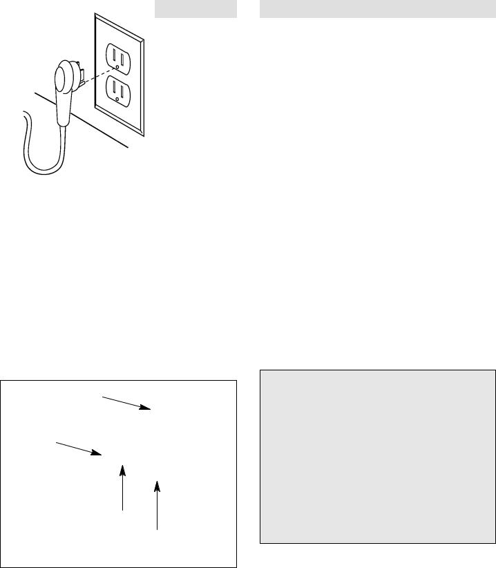
This appliance is factory equipped with a power supply cord with a three-prong grounding plug (with polarized parallel blades). It must be plugged into a mating grounding type receptacle, and connected to a correctly polarized 120 Volt circuit. If the circuit does not have a grounding type receptacle, it is the responsibility and obligation of the installer or user to have the existing receptacle changed to a properly grounded and polarized receptacle in accordance with all applicable local codes and ordinances by a qualified electrician. In the absence of local codes and ordinances the receptacle replacement shall be in accordance with the National Electrical Code.
THIS THIRD GROUND PRONG SHOULD NOT, UNDER ANY CIRCUMSTANCES, BE CUT OR REMOVED.
(SEE FIGURE 9)
Receptacle Box
Cover Plate
Three
Prong
Plug
Ground
Prong
Three Prong
Receptacle
FIGURE 9
STEP 5: GAS REQUIREMENTS
Verify the type of gas supplied to the location.
The range is shipped from the factory set up and adjusted for natural gas or LP gas (propane), depending on model ordered.
Natural Gas Requirements
Connection: 1/2 N.P.T. Minimum 5/8 dia. flex line. Pressure: 6 to 14 W.C.
LP Gas Requirements
Connection: 1/2 N.P.T., Minimum 5/8 dia. flex line. Pressure: 11 to 14 W.C.
A regulator is required at the LP source to provide a maximum of 14 W.C. to the range regulator.
Hook Up
A manual valve must be installed external to the appliance, in a location accessible from the front for the purpose of shutting off the gas supply. The supply line must not protrude beyond the back of the unit. Make sure the gas supply is turned off at the wall valve before connecting the appliance.
The gas supply connections should be made by a competent technician and in accordance with local codes or ordinances. In the absence of a local code, the installation must conform to the National Fuel Gas Code ANSI 223.1-Latest Edition.
CAUTION
The appliance must be isolated from the building’s gas supply piping system by closing its individual manual shut-off valve during any pressure testing of the gas supply piping system at test pressures equal to or less than 1/2 psig (3.5kPa.).
The appliance and its individual shut-off valve must be disconnected from the gas supply piping system during any pressure testing of the system at the test pressures in excess of 1/2 psig (3.5kPa.).
When checking the manifold gas pressure, the inlet pressure to the regulator should be at least 7.0 W. C. for natural gas.
** The flex line for the gas supply must be metal and be approved by an approved certifying agency (AGA, CGA, or U.L.). Never use a hose made of rubber or other synthetic material, as the heat may cause the hose to melt and develop leaks.
10
STEP 6: BACKGUARD INSTALLATION
The backguard must be installed when there is less than a 12 clearance between combustibles and the back of the range above the cooking surface (see Figure 3B).
RANGE BACKGUARD KITS
HIGH SHELF:
(22 ) PRAG3022 - 30 PRAG3622 - 36 PRAG4822 - 48
LOW SHELF: |
|
|
|
(12 ) |
PRAG3612 |
- |
36 |
|
PRAG4812 |
- |
48 |
The backguard is inserted, as shown in Figure 12, into the guide channels on the back of the range. Secure the backguard with the (4) sheet metal screws provided.
FIGURE 12
STEP 7: TEST AND ADJUSTMENT
CAUTION
For Warranty coverage, Jenn-Air requires that burner adjustments be made by a qualified technician at the time of installation. Extreme care should be used when adjustments are made after installation.*
*Improper or lack of adjustments will void your warranty.
Oven and Griddle Burners
Check for the proper burner flame characteristics and adjust air shutters if necessary (see figures 13 - 14). Each valve and air shutter is individually tested and adjusted prior to shipment. Normally adjustment is not required, however, vibration during transit or variations in the local gas supply may make minor adjustments necessary.**
Burner flames should be blue and stable with no yellow tips, excessive noise or lifting of the flame from the burner. (Slight yellow - tipping is normal with LP gas). If any of these conditions exist, check that the air shutter or burner ports are not blocked. If this condition persists, adjust the air shutter as required.
If the flame is too yellow, indicating insufficient air, adjust the shutter counterclockwise to increase air inlet.
If the flame is noisy or tends to lift away from the burner, indicating too much air, turn the shutter clockwise to reduce air.
The oven burner flames should be approximately 1-1/2 high. The griddle burner flames should be 1-1/2 to 2 (see figure 13).
Typical Section of Proper Flame (Approx.)
(Griddle / Oven)
1-1/2 - 2
FIGURE 13
Screen should |
Flame should be |
be glowing red |
approximately 1/8 |
|
thick and blue |
|
FIGURE 14 |
|
|
** The oven infra-red broiler burner has no air shutter and is not adjustable when used with natural gas. It is necessary to operate the oven broiler for 45 minutes to eliminate the harsh odor of the insulation binder. This must be done before using the range for the first time and with proper ventilation.
11

Surface Burners
The surface burners are not adjustable. Proper operation is achieved when the correct orifices for the gas supply are installed at the factory, based on model ordered.
* If the top burner does not ignite, check the spark igniter by listening for a clicking sound. If you do not hear the igniter click, turn off the burner. Check for a tripped circuit breaker, blown fuse, or poor wire connection to the igniter.
To Clean Exterior Surfaces
The stainless steel surfaces may be cleaned by wiping with a damp soapy cloth. Any mild glass cleaner will remove fingerprints and smears. Do not use steel wool as it will scratch this surface. Small scratches may be removed by lightly sanding, with the grain, using 120 grit paper.
INSTALLER FINAL CHECK LIST
j Placement of unit.
j Specified clearance maintained to cabinet surfaces. j Unit level - front to back, side to side.
j All packaging material and tie straps removed.
jLow back or high shelf backguard attached if there is less than 12 clearance above the cooking surface to combustibles behind unit.
Electrical
jReceptacle with 15 ampere over-current protection is provided for service cord connection.
j Adequate ground connection.
j Kick panel in place and two (2) screws secure.
Gas Supply
jConnection: 1/2 NPT with a minimum 5/8 diameter flex line.
jSite gas supply is compatible with range model, and sufficient pressure is available (see Gas Requirements on page 10).
jManual gas shut off valve installed in an accessible location.
j Unit tested and free of gas leaks.
Operation
jAll internal packing materials removed. Check drip drawers.
jBezels centered on burner knobs and knobs turn freely.
jEach burner lights satisfactorily, both individually and with other burners on same side of unit operating.
j Griddle is level.
j Drip trays are properly in place and pull out freely.
jOven door hinges seated and door opens and closes properly.
jBurner grates correctly positioned, level, and do not rock.
12
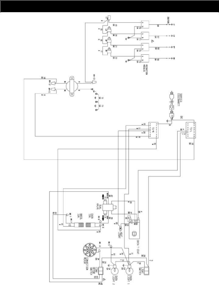
JENN-AIR PRG3010 WIRING DIAGRAM
Part No.: 16565-50 12/03 Rev. C
13
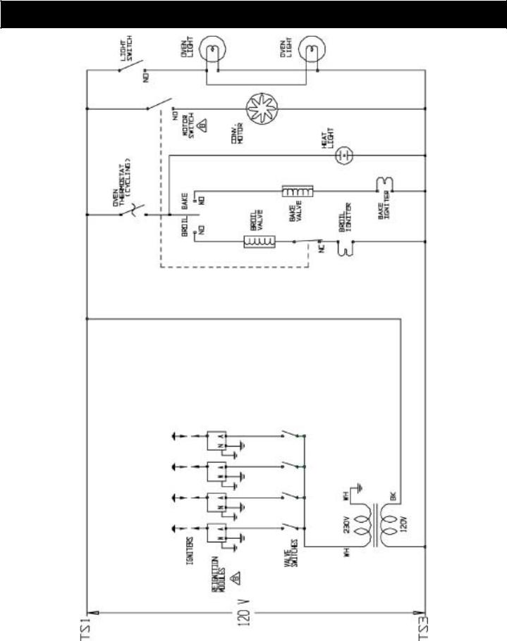
JENN-AIR PRG3010 WIRING SCHEMATIC
RR |
RR |
RF |
RF |
LR |
LR |
LF |
LF |
Part No.: 16565-50 12/03 Rev. C
14
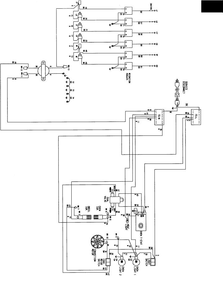
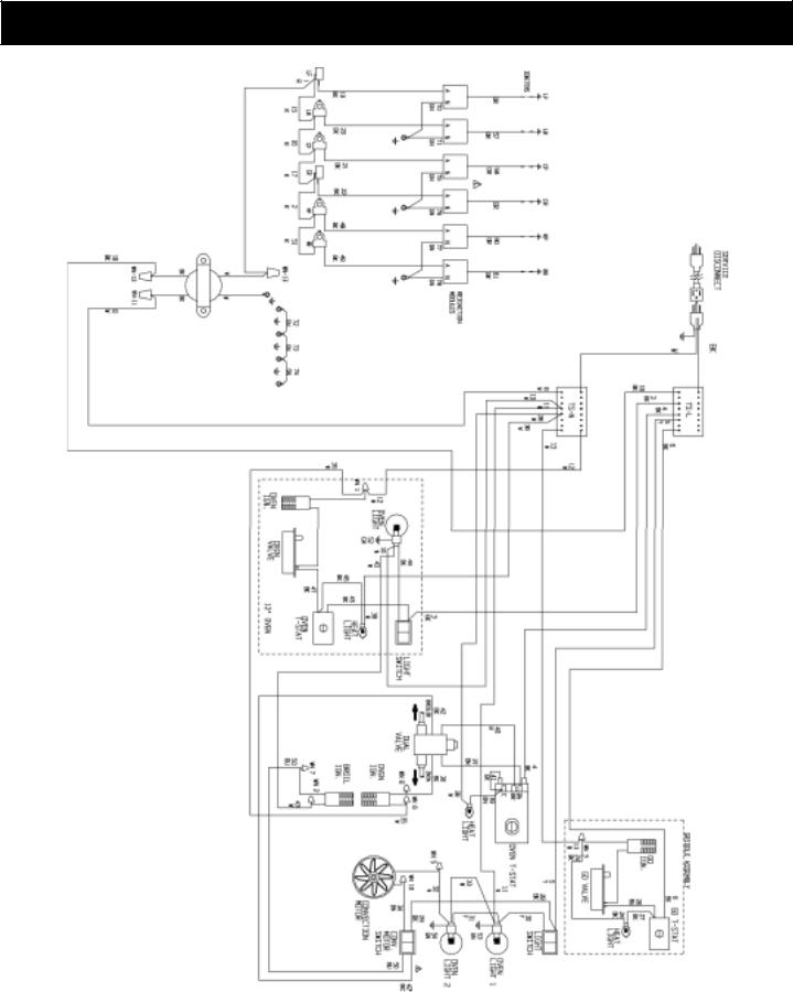
JENN-AIR PRG3610 WIRING DIAGRAM
Part No.: 16560-50 12/03 Rev. C
15
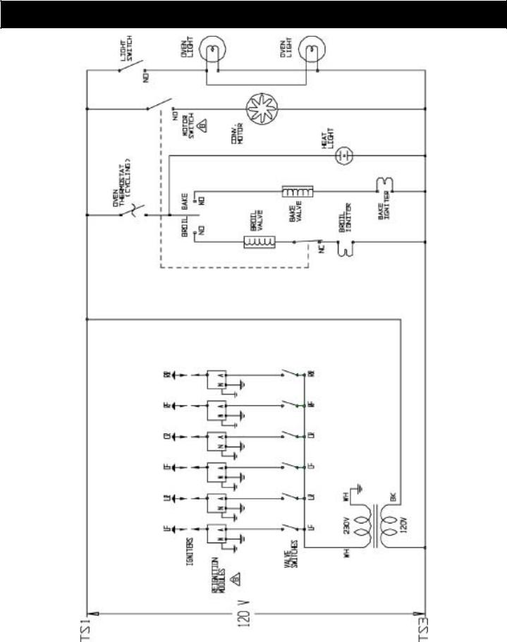
JENN-AIR PRG3610 WIRING SCHEMATIC
Part No.: 16560-50 12/03 Rev. C
16
JENN-AIR PRG4810 WIRING DIAGRAM
Part No.: 16561-50 12/03 Rev. C
17
 Loading...