


SMS1
Soundzone Music System
For Business Music
Preliminary Owners Manual

These products are in compliance with the EMC Directive 89/ 336/EEC and Article 10 (1) of the directive. In compliance with Technical Regulations EN50081-1 and EN50082-1. For a copy of the model-specific CE Declaration of Conformity, contact JBL at the address listed at the end of this manual.
Table of Contents
Quick Start Guide . . . . . . . . . . . . . . |
. |
1 |
|
Introduction . . . . . . . . . . . . . . . . |
. |
2 |
|
Components and Parts . . . . . . . . . . . |
. |
3 |
|
Installation . . . . . . . . . . . . . . . . . |
. |
7 |
|
Placement . . . . . . . . . . . . . . . . . |
. |
7 |
|
Coverage |
. . . . . . . . . . . . . . . . . |
. |
8 |
Satellites . . . . . . . . . . . . . . . . . . |
. |
8 |
|
Subwoofer . . . . . . . . . . . . . . |
. |
9 |
|
Wall Mounting . . . . . . . . . . . . |
. |
10 |
|
Floor Placement . . . . . . . . . . . |
. 10 |
||
Running Wires . . . . . . . . . . . . |
. 10 |
||
Installation and Hookup of the Subwoofer . . |
. 11 |
||
Installation and Hookup of the Satellites . . . |
. 14 |
||
Tuning . . . . . . . . . . . . . . . . . . . |
. |
16 |
|
Additional Applications . . . . . . . . . . . |
. 18 |
||
Technical Specifications . . . . . . . . . . |
. 19 |
||
Warranty & Contacting JBL . . . . . . . . . |
. 20 |
||
Quick Start Guide
The Following is a set of steps that will get the SMS1 Business Music System up and playing quickly. For more detailed descriptions, explanations, and setup, please read the rest of this manual. After each step, the section that covers the step in more detail noted in Italics.
Step 1 – Remove the subwoofer cabinet from the wall baffle by removing the screws from all of the mounting tabs. Be sure to disconnect the subwoofer driver cable. {Installation and Hookup of the Subwoofer}
Step 2 – If the subwoofer is going to be mounted on a wall, attach the wall baffle to the wall now. {Installation and Hookup of the Subwoofer}
Step 2 – Plug the IEC power cord into the socket on the electronics module. Connect your input source to the proper jack on the connector panel. Run all wiring through the provided junction boxes and knockouts. {Installation and Hookup of the Subwoofer}
Step 3 – Using the green block connectors, connect the speaker wire to all four speaker outputs on the connector panel. Run all wiring through the provided junction boxes and knockouts. {Installation and
Hookup of the Subwoofer}
Step 4 – Connect each of the SMS-Sat’s to the speaker wires. Be sure the Speaker EQ Switch is in the ON (Normal) position. {Installation and Hookup of the Satellites}
Step 5 – Plug the power cord into an AC wall socket. {Installation and Hookup of the Subwoofer}
Step 6 – Reconnect the subwoofer driver cable to the electronics module, and re-attach the subwoofer cabinet to the wall baffle. {Installation and Hookup of the Subwoofer}
Step 7 – Make sure the music volume on the control panel is turned down and turn the power on. {Tuning}
Step 8 – Start the source, then gradually turn the volume up. {Tuning}
Step 9 – Set the volume to a comfortable level. Now be sure the Crossover Switch is in the 160Hz (Normal) position. Press the Input CH Polarity Switch several times. Leave it in the position that gives the most bass. {Tuning}
Step 10 – Use the Subwoofer Trim knob to set the bass balance. {Tuning}
Step 11 – Turn the Volume up to the highest expected listening level. Adjust the AutoWarmth Knob so that the Red LED just begins to light up. Then turn the volume down to a normal listening level. {Tuning}
Step 12 – Attach the Security Panel. {Tuning}
1
Introduction
Thank you for purchasing the SMS1 Soundzone Business Music System. The SMS1 is an all-in-one solution for businesses that require high quality sound with a minimum of complexity, and a minimum price.
Businesses all around the world are becoming increasingly aware of the positive effect music can have on customers. The overall experience offered by a business is becoming the most important part of capturing the attention of consumers, even more than the actual product or service that is offered. The popularity of high quality, demographically focused music in a business venue can provide tremendous sales impact.
However, getting good sound with minimal complexity and a minimum price has been difficult in the past. The SMS1 System has been designed to eliminate the complexity, provide great sound all the time and at all volumes, and provide more economical choices to businesses that wish to harness the benefits of quality audio.
The SMS1 also offers a tremendous degree of configuration options. It is designed for use as a standalone system, but can be used in several other ways. Multiple SMS-1 Systems can be used together for more coverage in a variety of ways. The SMS1 System can be used in conjunction with other sound systems for providing just the right sound for just the right area. And the SMS1 SUB powered subwoofer can be used separate from the SMS1-SAT’s for even greater flexibility.
There are so many possibilities, due to the versatility of the SMS1 components, that it would be virtually impossible to cover every one of them in detail in this manual. It would also be impossible to anticipate all of the possible uses. To that extent, this manual will provide the underlying knowledge that will allow any user to adapt the SMS1 to their needs, without undue complexity, and with consistently high quality results.
The first step is to briefly name and discuss the various parts included in the SMS1 Package.
2
Components and Parts
Please take a moment to familiarize yourself with all of the parts.
This will help you as you progress through the manual, and as you set up the system.
SMS1-System
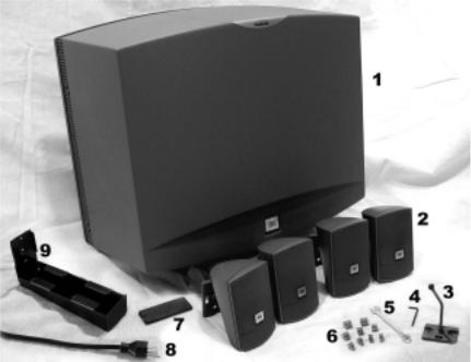
Figure 1 – SMS1 System Components
1 - SMS1-SUB - This is the Subwoofer Module. It houses the Low Frequency Loudspeaker, one 120 Watt amplifier for the Subwoofer, two 20 Watt amplifiers for the Satellites, and the Soundzone Electronics. Please see Figure 2 for more detail on the Subwoofer Module.
2 - SMS1-SAT – There are four Satellites in a complete system. These are the loudspeakers for all of the middle and higher frequencies.
3 - InvisiBall – There are four of these in a complete system. They are the only hardware you need for installing the SMS1 -SAT’s on a solid surface.
4 - Hex Key Wrench - This INCLUDED 3mm Hex Wrench is used for loosening and tightening the InvisiBall mechanism in the SMS1-SAT’s.
5 - Wrench – This INCLUDED Wrench is for tightening the InvisiBall Arm onto the base.
6 - Block Connectors – These Block Connectors are provided for making all input and output connections from the Connector Panel.
7 - Security Panel – Covers the tuning controls after setup to prevent tampering.
8 - Power Cord – This cord attaches to the IEC Power Input Jack on the Electronics module and connects to an AC Power Outlet for supplying power to the module.
9 - Subwoofer Feet – There are two feet in a complete system. They are required if the Subwoofer is to be set on a floor or shelf.
3

SMS1-SUB
This section gives detail of the parts of the Subwoofer Module.
Figure 2 – Subwoofer Cabinet
1 - Cabinet Chassis – This is the main body of the low frequency cabinet. 2 - Driver – Low frequency Element
3 - Port Tube – This is one of the primary sound radiation locations.
4 - Grille Trim – These pieces go on after installation to trim and protect the module. 5 - Subwoofer Leads -These connect to the Electronic Module Subwoofer output.
6 - Rubber Screw Cover Pieces (not shown) - These pieces are used to cover the mounting screws when the Subwoofer is assembled.
Wall Baffle and Electronic Module
Figure 3 –Wall Baffle and Module
1 - Wall Baffle – This baffle is the primary mounting point. It is also the physical mount for the Electronic Module
2 - Electronic Module – This is the housing for all of the electronics, the connections and the controls.
More detail is shown in Figure 4.
3 - Knockouts – These prepunched Knockouts provide a location at which to connect
input and output conduit. There are two diameters accounted for 1/2” and 3/4”.
4 - Mounting Tabs – These tabs are for lining up and attaching the Subwoofer Cabinet to the Wall Baffle. 5 - Installation Points – These holes are molded in position to match with several standard dimensions for
wall stud placement. They accommodate 5/32 in. (4mm) Bolts.
6 - Power Cord Input Jack – This Jack is for the IEC Power Input Cord to supply power to the SMS1 System.
4

Control Panel and Connector Panel
Figure 4a: Control Panel
1 - Power Switch – Use this switch to turn the System on and off. 2 - Power LED – This LED illuminates when the Power is ON.
3 - Security Panel Attachment Points – The INCLUDED Security Panel is attached here using the INCLUDED screws and standoffs. This panel covers the trim controls to prevent unauthorized tampering .
4 - Input CH Polarity Switch – This switch changes the polarity of the input to the Subwoofer. Its function is clearly detailed in the TUNING section of the Manual. Adjust this switch for most Bass.
5 - Crossover Switch – This switch changes the crossover point for the Subwoofer and Satellites. In the outward position, labeled “NORMAL,” the crossover is set at 160 Hz (for use with SMS1-SAT’s). This is the proper position for use with the system’s SMS1-SAT satellite speakers. The pushed-in position sets the crossover at 80 Hz for applications in which you need the Subwoofer to simply augment the bass of a full-range system.
6 - Subwoofer Trim Knob – This knob adjusts the amount of Subwoofer level in the acoustic mix. Turn the knob CLOCKWISE for more bass, COUNTER-CLOCKWISE for less Bass. LevelGuard may not protect the sytem from damage when the subwoofer trim control is turned all the way up. Be careful not to set this too high.
7 - AutoWarmth LED – This LED illuminates when the AutoWarmth circuitry is actively responding to the music. AutoWarmth is covered in detail in the TUNING Section of the Manual.
8 - AutoWarmth Trim Knob – This knob adjusts the amount of AutoWarmth in the Signal Path. AutoWarmth is covered in detail in the TUNING Section of the Manual.
9 - Page Sensitivity Trim Knob – This knob adjusts the sensitivity of the Page Ducking circuitry to the incoming Page Signal. Turn CLOCKWISE for greater Sensitivity, turn COUNTERCLOCKWISE for less sensitivity. Adjust this control so the mic makes the music go down in volume during a page, but so that the page ducking does not falsely trigger when a page isn’t occuring.
10 - Mic Volume Knob – This knob adjusts the output volume of the signal from the Paging Microphone. 11 - Volume Knob – This knob adjusts the music volume but does NOT affect the mic paging volume. 12 - LevelGuard LED – This LED illuminates when the LevelGuard Circuitry is actively responding to the
signal. LevelGuard lowers high volume signals. It’s acceptable for this LED to flash on for as much as 50% of the time, as long as the sound from the speakers is not audibly distorted.
5
 Loading...