


MA6004
MA6004
MA6002
MARINE AUDIO
POWER AMPLIFIER
OWNER’S MANUAL
www.jbl.com
The Official Brand of Live Music.

INSTALLATION
THANK YOU
for purchasing a JBL marine amplifier. In
order that we may better serve you should
you require warranty service for your
new amplifier, please retain your original
purchase receipt and register your new
JBL amplifier online at www.jbl.com.
WARNING
Playing loud music in a boat can hinder
your ability to hear other boats, passengers
and nearby swimmers and can permanently
damage your hearing. We recommend
listening at low or moderate levels while
operating your boat. JBL accepts no liability
for hearing loss, bodily injury or property
damage resulting from the use or misuse
of this product.
IMPORTANT
To get the best performance from your
JBL marine amplifiers, we strongly
recommend that installation be entrusted
to a qualified professional. Although
these instructions explain how to install
these amplifiers in a general sense, they
do not show specific installation methods
that may be required for your particular
application. If you do not have the
necessary tools or experience, do not
attempt the installation yourself. Instead,
ask your authorized JBL car audio or marine
audio dealer about professional installation.
NOTE: This marine product is not intended
for automotive applications.
INSTALLATION
WARNINGS AND TIPS
• Always wear protective eyewear when
using tools.
• Turn off the audio system and other
electrical devices before you start.
Disconnect the (–) negative lead from
your boat’s battery.
• At the installation sites, locate and
make a note of all fuel lines, hydraulic
brake lines, vacuum lines and electrical
wiring. Use extreme caution when cutting or drilling in and around these areas.
• Check clearances on both sides of
a planned mounting surface before
drilling any holes or installing any
screws. Remember that the screws
can extend behind the surface. Do not
use screws long enough to penetrate
the boat’s hull.
• Before drilling or cutting holes, use a
utility knife to remove unwanted fabric
or vinyl to keep material from snagging
in a drill bit.
• When routing cables, keep input-signal
cables away from power cables and
speaker wires.
• When making connections, make
certain they are secure and properly
insulated.
• If the amplifier’s fuse must be replaced,
use only the same type and rating as
that of the original. Do not substitute
another kind.
CHOOSING A LOCATION
AND MOUNTING THE
AMPLIFIER
Choose a mounting location in the
cargo area where the amplifier will not
be damaged by shifting cargo or water.
Although these JBL marine amps are
designed for use on a boat, they will not
withstand submersion. Amplifier cooling
is essential for proper amplifier operation.
If the amplifier is to be installed in an
enclosed space, make sure there is
sufficient air circulation for the amplifier
to cool itself.
Make sure that the amplifier is mounted
securely using nuts and bolts or the
supplied mounting screws.
2
INSTALLATION
NC
NO
+
12V
AMP REM
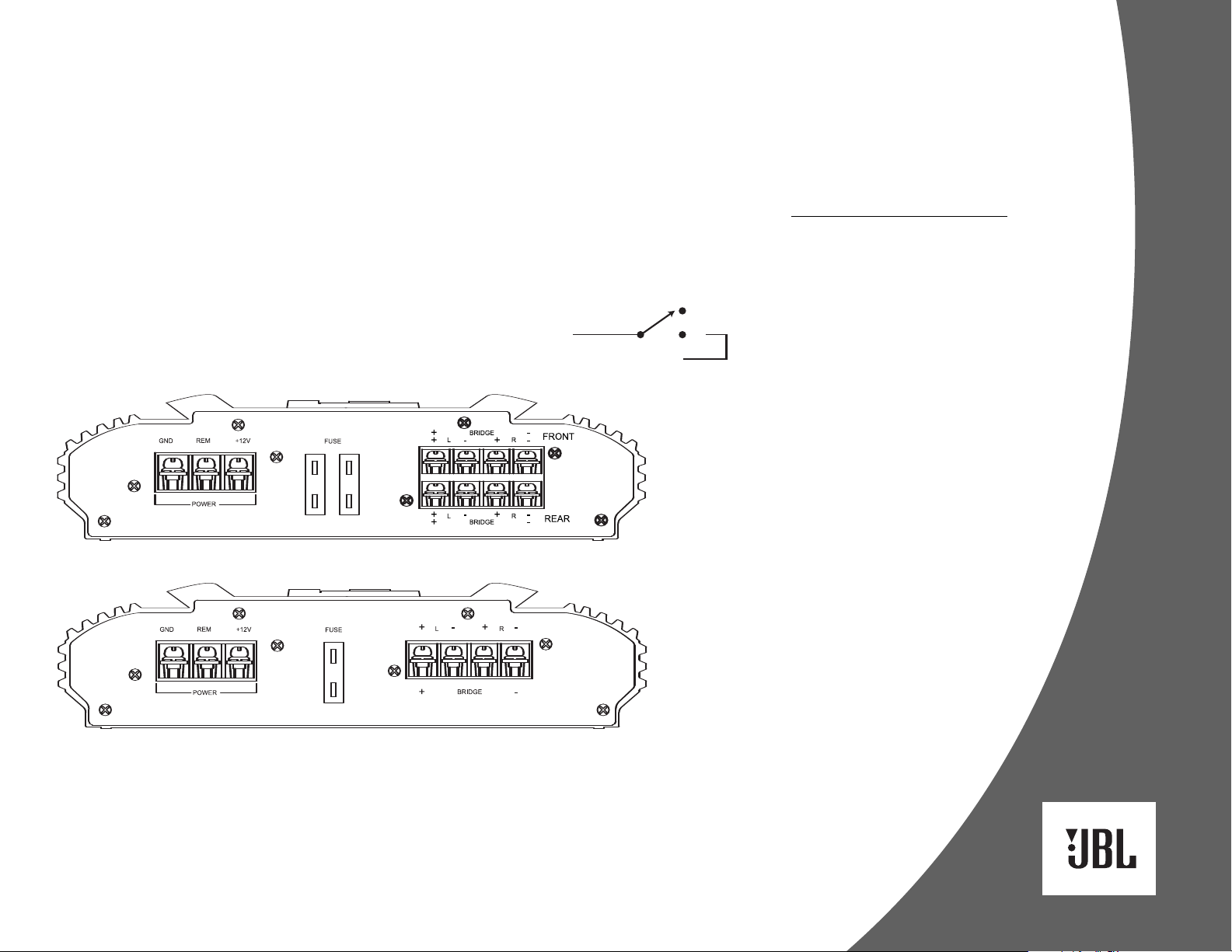
POWER CONNECTIONS
The amplifier requires a reliable
connection to the boat’s electrical
system in order to perform optimally.
See Figures 1 and 2 for terminal connection locations. Please adhere to
the following instructions carefully:
Ground Connection
Connect the amplifier’s Ground (GND)
terminal to the battery’s negative terminal,
using a ring terminal. Refer to the wire gauge
chart to determine minimum wire gauge size.
Figure 1. Terminal connection end plate for MA6004.
Power Connection
Connect a wire (see chart at right for
appropriate gauge) directly to the positive
battery terminal, and install an appropriate
fuse holder within 18" of the battery terminal.
Do not install the fuse at this time. Route
the wire to the amplifier’s location, and
connect it to the amplifier’s Positive (+12V)
terminal. Be sure to use appropriate
grommets whenever routing wires through
a bulkhead or other obstruction.
adequately protect the positive wire from
potential damage may result in a fire. When
you are done routing and connecting this
wire, you may install the fuse at the battery.
Failure to
Remote Connection
Connect the amplifier’s Remote (REM)
terminal to the source unit’s Remote TurnOn lead using a minimum of 18-gauge wire.
NOTE: If your source unit does not have
a remote turn-on connection, connect
the amplifier’s (REM) terminal to a wire
that provides +12V when the boat’s accessories are on or when the key is switched
on. If no such circuit exists, install a
switch. See Figure 3.
Figure 3. Install a switch for the Remote
Turn-On lead.
Speaker Connections
Refer to the application guides on the
pages that follow. Speaker connections
should be made using a minimum of
16-gauge wire.
Wire Gauge Chart
Amplifier Maximum Minimum
Model Current Draw Wire Gauge
MA6002 22A #8 AWG
MA6004 40A #8 AWG
These recommendations assume 10' – 12'
wire runs. If your amplifier will be mounted
farther than 12' from the boat’s battery, use
a larger gauge.
Figure 2. Terminal connection end plate for MA6002.
3
 Loading...