


®
JBL CINEMA SOUND™
CST55, CSB5, CSC55, CSS10
OWNER’S GUIDE
THANK YOU FOR CHOOSING JBL
For more than 60 years, JBL has been involved in every aspect of music and film recording and reproduction, from live performances to the recordings you play in your home, car or office.
We’re confident that the JBL system you have chosen will
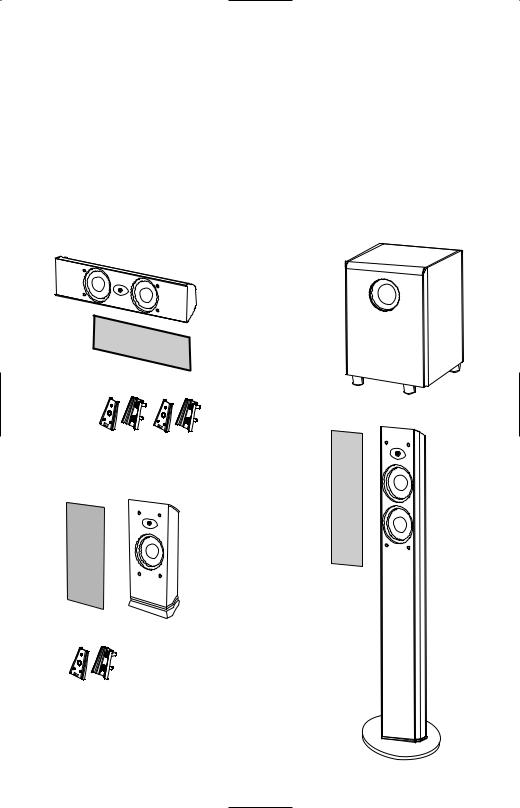
INCLUDED
CSC55
provide every note of enjoyment that you expect –
and that when you think about purchasing additional audio equipment for your home, car or office, you will once again choose JBL.
Please take a moment to register your product on our
Web site at www.jbl.com. It enables us to keep you
posted on our latest advancements, and helps us to better understand our customers and build products that meet their needs and expectations.
JBL, Incorporated
CSS10
Grille
CST55
(2) Wall brackets
CSB5
Grille
Grille
(1) Wall bracket
2
READ FIRST! Important Safety Precautions!
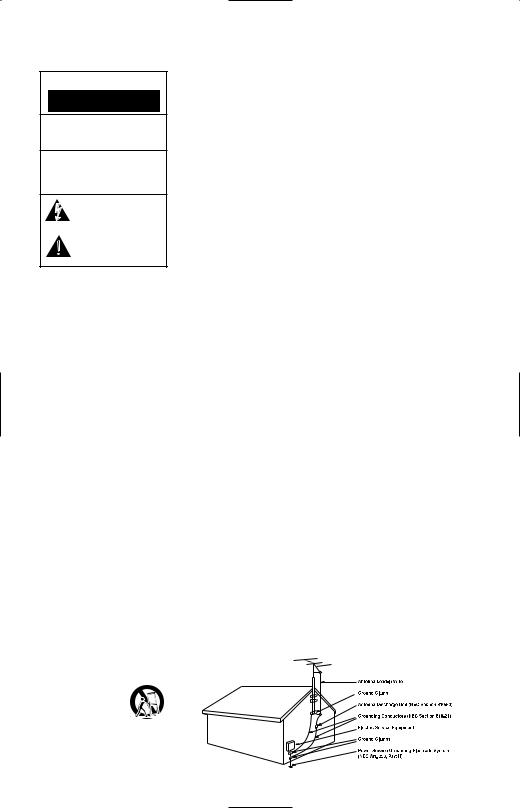
CAUTION
RISK OF ELECTRIC SHOCK
DO NOT OPEN
CAUTION: To reduce the risk of electric shock, do not remove cover (or back).
No user-serviceable parts inside. Refer servicing to qualified service personnel.
CAUTION: To prevent electric shock, do not use this (polarized) plug with
an extension cord, receptacle or other outlet unless the blades can be fully inserted to prevent blade exposure.
The lightning flash with arrowhead symbol, within an equilateral triangle, is intended to alert the user to the presence of uninsulated “dangerous voltage” within the product’s
enclosure that may be of sufficient magnitude to constitute a risk of electric shock to persons.
The exclamation point within an equilateral triangle is intended to alert the user to the presence of important operating and maintenance (servicing) instructions in the
literature accompanying the appliance.
1.Read these instructions.
2.Keep these instructions.
3.Heed all warnings.
4.Follow all instructions.
5.Do not use this apparatus near water.
6.Clean only with a dry cloth.
7.Do not block any ventilation openings. Install in accordance with the manufacturer’s instructions.
8.Do not install near any heat sources such as radiators, heat registers, stoves or other apparatus (including amplifiers) that produce heat.
9.Do not defeat the safety purpose of the polarized or grounding-type plug. A polarized plug has two blades with one wider than the other. A grounding-type plug has two blades and a third grounding prong. The wide blade or the third prong are provided for your safety. If the provided plug does not fit into your outlet, consult an electrician for replacement of the obsolete outlet.
10.Protect the power cord from being walked on or pinched, particularly at plugs, convenience receptacles and the point where they exit from the apparatus.
11.Only use attachments/accessories specified by the manufacturer.
12.Use only with the cart, stand,
tripod, bracket or table specified by the manufacturer or sold  with the apparatus.
When a cart is used,
use caution when moving
the cart/apparatus combination to avoid injury from tip-over.
13.Unplug this apparatus during lightning storms or when unused for long periods of time.
14.Refer all servicing to qualified service personnel. Servicing is required when the apparatus has been damaged in any way, such as power-supply cord or plug is damaged, liquid has been spilled or objects have fallen into the apparatus, the apparatus has been exposed to rain or moisture, does not operate normally, or has been dropped.
15.Do not use attachments not recommended by the product manufacturer, as they may cause hazards.
16.This product should be operated only from the type of power source indicated on the marking label. If you are not sure of the type of power supply to your home, consult your product dealer or local power company. For products intended to operate from battery power or other sources, refer to the operating instructions.
17.If an outside antenna or cable system is connected to the product, be sure the antenna or cable system is grounded so as to provide some protection against voltage surges and built-up static charges. Article 810 of the National Electrical Code, ANSI/NFPA 70, provides information with regard to proper grounding of the mast and supporting structure, grounding of the lead-in wire to an antenna discharge unit, size of grounding conductors, location of antennadischarge unit, connection to grounding electrodes, and requirements for the grounding electrode. See Figure A.
Figure A.
Example of Antenna Grounding as per National Electrical Code ANSI/NFPA 70
18.An outside antenna system should not be located in the vicinity of overhead power lines or other electric light or power circuits, or where it can fall into such power lines or circuits. When installing an outside antenna system, extreme care should be taken to keep from touching such power lines or circuits, as contact with them might be fatal.
19.Do not overload wall outlets, extension cords, or integral convenience receptacles, as this can result in a risk of fire or electric shock.
20.Never push objects of any kind into this product through openings, as they may touch dangerous voltage points or short-out parts, which could result in a fire or electric shock. Never spill liquid of any kind on the product.
21.The apparatus shall not be exposed to dripping or splashing, and no objects filled with liquids, such as vases, shall be placed on the apparatus.
22.Do not attempt to service this product yourself, as opening or removing covers may expose you to dangerous voltage or other hazards. Refer all servicing to qualified service personnel.
23.When replacement parts are required, be sure the service technician has used replacement parts specified by the manufacturer or that have the same characteristics as the original part. Unauthorized substitutions may result in fire, electric shock or other hazards.
24.Upon completion of any service or repairs to this product, ask the service technician to perform safety checks to determine that the product is in proper operating condition.
25.The product should be mounted to a wall or ceiling only as recommended by the manufacturer.
3
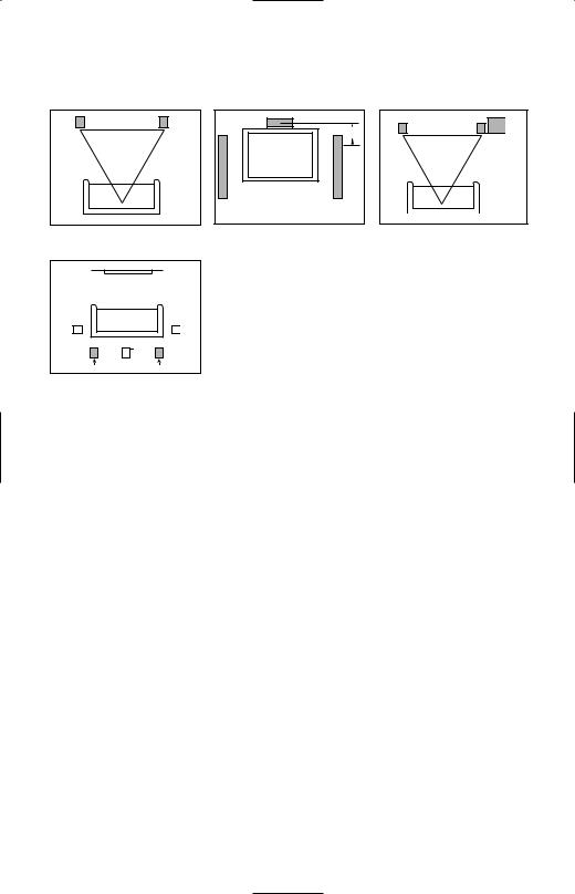
SPEAKER PLACEMENT |
|
|
FRONT |
CENTER CHANNEL |
|
SPEAKERS |
SPEAKER |
SUBWOOFER |
|
0–2 ft |
|
|
0–0.6m |
|
SURROUND SPEAKERS
† Single surround back speaker may be used with 6.1 receivers and processors.
Alternate placement for surround speakers when only 5.1 channels are used; required placement for surround back speakers in 7.1-channel systems.
The front speakers should be placed the same distance from each other as they are from the listening position. The CSB5 speakers should be placed at about the same height from the floor as the listeners’ ears will be, or they may be angled toward the listeners.
The center channel speaker should be placed slightly behind the front left and right speakers, and no more than 2 feet (0.6m) above or below the tweeters of the left and right speakers. It is often convenient to set the center speaker on top of the television set, as shown in the drawing.
The JBL Cinema Sound speaker system may be used in 5.1-, 6.1- or 7.1-channel applications. In 5.1-channel applications, two of the sur-
round speakers should be placed slightly behind the listening position and, ideally, should face each other and be at a level higher than the listeners’ ears. If that is not possible, they may be placed against a wall behind the listening position, facing forward. In 6.1-channel applications, two of the surround speakers should be placed in the side positions, and a single surround back speaker should be placed against the wall behind the listening position. In 7.1-channel applications, place two of the surround speakers in the side positions, and place the two surround back speakers against the rear wall.
In Dolby® Digital and DTS® systems, it is best to aim all of the speakers (except the subwoofer) toward the listening position at or slightly
above about ear-level height. In systems where only analog surround processing (such as Dolby Pro Logic® II) is available, it may be preferable to aim the speakers straight out from the wall to obtain a more diffuse sound.
The low-frequency material reproduced by the subwoofer is mostly omnidirectional, and this speaker may be placed in a convenient location in the room. However, bass reproduction will be maximized when the subwoofer is placed in a corner along the same wall as the front speakers. Experiment with subwoofer placement by temporarily placing the subwoofer in the listening position and moving around the room until the bass reproduction is best. Place the subwoofer in that location.
4
 Loading...