


 Loading...
CV-M77
Progressive Scan Camera
CV-M77
Operation Manual
Camera: Revision A
Manual: Version 1.0
- 1 -

CV-M77
- 2 -

CV-M77
1 |
General...................................................................................................................... |
5 |
|
2 |
Standard Composition............................................................................................. |
5 |
|
3 |
Main Features ........................................................................................................... |
5 |
|
4 |
Camera Housing and Dimensions .......................................................................... |
6 |
|
5 |
Pin Assignment ........................................................................................................ |
7 |
|
5.1 |
12-pin Multi-connector (DC-IN/SYNC.).................................................................................... |
7 |
|
5.2 |
6-pin Multi-connector (RS 232C/TRIGGER)............................................................................ |
7 |
|
5.3 |
9-pin DSUB-connector (RGB/SYNC.) ..................................................................................... |
8 |
|
5.4 |
Input and Output Circuits......................................................................................................... |
9 |
|
5.4.1 |
|
Video input ........................................................................................................................... |
9 |
5.4.2 |
|
Trigger input ........................................................................................................................ |
9 |
5.4.3 HD and VD input .................................................................................................................. |
9 |
||
5.4.4 HD, VD, PCLK, WEN and EEN output.................................................................................... |
9 |
||
6 |
Functions and Operation....................................................................................... |
10 |
|
6.1 |
Input/Output of HD/VD Signal................................................................................................ |
10 |
|
6.1.1 Input of External HD/VD signals......................................................................................... |
10 |
||
6.1.2 Output of Internal HD/VD signals ....................................................................................... |
10 |
||
6.2 |
Continuous operation ............................................................................................................ |
10 |
|
6.3 |
External Trigger Mode........................................................................................................... |
10 |
|
6.3.1 Edge Pre-select Trigger Mode ........................................................................................... |
10 |
||
6.3.2 Pulse Width Control Trigger Mode ..................................................................................... |
11 |
||
6.3.3 |
|
Frame-delay Readout Mode .............................................................................................. |
12 |
6.3.4 Long Time Exposure Mode ................................................................................................ |
12 |
||
6.4 |
Timing diagram for Horizontal and Vertical Sync. Video Output ........................................... |
13 |
|
6.5 |
Timing diagram for Edge Pre-select mode............................................................................ |
14 |
|
6.6 |
Timing diagram for Pulse Width Control mode...................................................................... |
14 |
|
6.7 |
Timing diagram for Frame-delay Readout mode................................................................... |
14 |
|
6.8 |
Timing diagram for Long Time Exposure mode .................................................................... |
15 |
|
7 |
Configuring the camera using the serial interface.............................................. |
16 |
|
7.1 |
Mode Setting using ASCII commands via the RS-232C port. ............................................... |
16 |
|
7.2 |
Communication setting.......................................................................................................... |
16 |
|
7.3 |
Command Protocol................................................................................................................ |
16 |
|
7.3.1 |
|
Receiving Data (Camera->PC) .......................................................................................... |
17 |
7.4 |
RS232C Cable Connections.................................................................................................. |
18 |
|
8 |
Switch Settings ...................................................................................................... |
19 |
|
8.1 |
Mode Settings by Switch ....................................................................................................... |
19 |
|
8.2 |
Signals by Switch Settings .................................................................................................... |
19 |
|
8.2.1 |
|
SW301 switch .................................................................................................................... |
19 |
8.2.2 |
|
SW302 switch .................................................................................................................... |
20 |
8.2.3 |
|
SW303 switch .................................................................................................................... |
20 |
9 |
Jumper settings ..................................................................................................... |
21 |
|
9.1 |
Jumper locations ................................................................................................................... |
21 |
|
9.2 |
Jumper table.......................................................................................................................... |
22 |
|
10 |
CV-M77 Camera Control Tool................................................................................ |
23 |
|
11 |
Specifications......................................................................................................... |
25 |
|
11.1 |
|
Spectral sensitivity ............................................................................................................. |
26 |
12 |
Appendix................................................................................................................. |
27 |
|
12.1 |
|
Precautions ........................................................................................................................ |
27 |
12.2 |
|
Typical CCD Characteristics .............................................................................................. |
27 |
12.2.1 |
Smear ............................................................................................................................. |
27 |
|
12.2.2 |
Aliasing ........................................................................................................................... |
27 |
|
12.2.3 |
Blemishes ....................................................................................................................... |
27 |
|
|
|
|
|
|
|
- 3 - |
|

|
|
CV - M77 |
12.2.4 Patterned Noise |
.............................................................................................................. 27 |
|
12.3 |
References......................................................................................................................... |
27 |
13 |
Users Record.......................................................................................................... |
28 |
14 |
Index........................................................................................................................ |
28 |
- 4 -

CV-M77
1 General
The CV-M77 camera is a compact RGB color progressive scan camera designed for automated imaging applications. The 1/3" CCD sensor with square pixels and primary mosaic filter offers a superb image quality and the build in DSP assures high color reproduction.
The camera incorporates several triggered modes and various shutter functions to capture moving objects and to control the light. All camera mode settings can be controlled via an RS-232C interface or by the switch at the rear of the camera.
The CV-M77 camera is ideal for demanding color applications such as color inspection, gauging and color printing.
The latest version of this manual can be downloaded from: www.jai.com .
The latest version of the Camera Control Tool software can be downloaded from: www.jai.com .
2 Standard Composition
The standard camera composition consists of the camera main body and the operation manual.
3Main Features
•New 1/3” full frame progressive scan interline transfer CCD
•RGB Primary color mosaic filters on chip
•1034 (h) x 779 (v) 4.65µm square pixels (1024 x 768 pixels read out) – XGA format
•25 full frames RGB video output per second
•Internal, external HD/VD or random trigger synchronization
•Edge pre-select and pulse width controlled external trigger modes
•Programmable shutter speed from 1.5 H to 791 H
•Long time exposure with external VD pulse interval
•Frame delay readout for edge pre-select and pulse width controlled shutter
•Exposure enable EEN, write enable WEN and pixel clock output
•Short ASCII commands for fast mode setup via serial port
•Windows Camera Control Tool software to setup the camera via RS 232C
•Pixel clock output optional
- 5 -
CV-M77
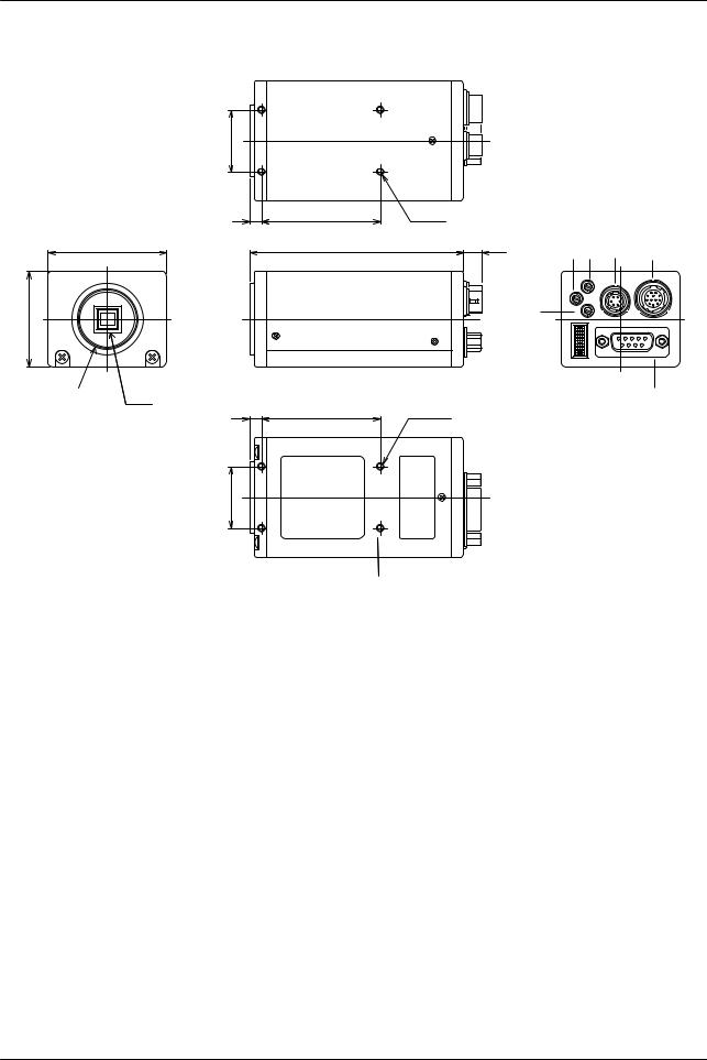
4 Camera Housing and Dimensions
26 (1.02)
5 |
50 |
4-M3 depth5 |
|
|
|
(0.2) |
(19.7) |
|
5 3 |
6 |
7 |
50 |
90 |
7.6 |
|||
(1.97) |
(3.54) |
(0.3) |
|
|
|
|
|
|
R |
|
|
40 (1.57) |
|
4 |
MG |
|
|
|
SW1B |
RS-232CTRIG |
DCIN |
||
1 (C-Mount) |
|
|
|
RGB/ SYNC |
|
|
|
|
|
8 |
|
2 (CCD chip) |
|
4-M3 depth5 |
|
|
|
5 |
50 |
|
|
|
|
(0.2) |
(19.7) |
|
|
|
|
26 (1.02) |
|
|
|
|
|
11
Figure 4-1
1Lens mount of C-mount type. *1)
21/3" interline transfer CCD progressive scan sensor with square pixels and
|
primary mosaic filter |
|
3 |
R Gain Potentiometer. |
To adjust Red gain level manually. |
4 |
B Gain Potentiometer. |
To adjust Blue gain level manually. |
5 |
MG Gain Potentiometer. |
To adjust Master gain level manually. |
66 pin connector for RS 232C signals, input of ext. trigger pulse and WEN output.
712 pin connector for +12V DC power and HD/VD input/output.
89 pin D-Sub connector for RGB video output, video synchronization output and pixel clock output.
9Switch to set shutter speed and function mode.
10Screw holes for tripod mounting plate (optional plate)
114 M3 mounting threads. *2)
*1) Note: Rear protrusion on C-mount lens must be less than 6mm (0.24-inch approx.)
*2) Note: Notice depth of thread is only 5mm. Too long screws may harm inside electronics.
- 6 -

CV-M77
5 Pin Assignment
5.112-pin Multi-connector (DC-IN/SYNC.)
Type: HR10A-10R-12PB-01 (Hirose male) Seen from rear.
1 9
2 10 8
3 11 12 7
4 6
5
Pin No. |
5.1.1.1 |
Signal |
5.1.1.2 Remarks |
|
1 |
|
5.1.1.3 |
GND |
|
2 |
|
+12V DC input |
|
|
3 |
|
GND |
|
|
4 |
|
NC |
|
|
5 |
|
GND |
|
|
6* |
|
Ext.HD input |
SW-S301.1 “ON” for 75Ω termination, SW-S303.1 “OFF” for HD output |
|
7* |
|
Ext.VD input |
SW-S301.2 “ON” for 75Ω termination, SW-S303.2 “OFF” for VD output |
|
8 |
|
GND |
|
|
9* |
|
NC |
PCLK out: JP305 “short”, JP306 “open” |
|
10* |
|
WEN |
NC: JP309 and JP310 “open”. GND: JP308 “open” JP309 and JP310 “short” |
|
11* |
|
Ext. trigger |
NC: JP401 and JP301* “open”. +12V DC JP401 “short” and JP301* “open” |
|
12 |
|
GND |
|
|
Notes: |
|
|
|
|
*) |
Signals on pin no. 6, 7,9,10 and 11 can be changed by jumper setting. |
|||
|
See section 8 “Switch Settings” and section 9 “Jumper Settings ” for more information. |
|||
*) |
In Edge Pre-select and Pulse Width Control mode do not input ext. VD signal. |
|||
*) |
When using the HD/VD, PCLK and WEN signals (input or output) from the 12-pin |
|||
|
connector do not use the same signals (input or output) from the 9 pin D-SUB connector. |
|||
*) |
JP301 is “short” by a capacitor (factory setting – see section 9 “Jumper Settings”. |
|||
*) |
Signals shown in bold italics are factory settings. |
|||
5.26-pin Multi-connector (RS 232C/TRIGGER)
Type: HR10A-7R-6PB (Hirose male)
Seen from rear.
Pin No. |
5.2.1.1 Signal |
5.2.1.2 Remarks |
|
|
1 |
|
TXD (RS-232C) |
|
|
2 |
|
RXD (RS-232C) |
|
|
3 |
|
GND |
|
|
4* |
|
NC |
GND: JP402 “short” |
|
5 |
|
Ext.TRIG input |
|
|
6* |
|
EEN output |
WEN out: JP312 “open” and JP311 “short” |
|
Notes: |
|
|
|
|
*) |
Signals on pin no. 4 and 6 can be changed by jumper setting. |
|||
|
|
|
|
|
|
|
|
- 7 - |
|

|
CV-M77 |
|
See section 8 “Switch Settings” and section 9 “Jumper Settings ” for more information. |
*) |
When using the WEN signal from the 6 pin connector do not use the same signal from the |
|
9 pin connector. |
*) |
Signals shown in bold italics are factory settings. |
5.39-pin DSUB-connector (RGB/SYNC.)
Pin No. |
5.3.1.1 Signal |
5.3.1.2 Remarks |
1* |
NC |
VD input: JP303 “open” and JP304 “short” |
2 |
GND |
|
3 |
R output |
|
4* |
G output |
Sync. on G: SW302-3 “ON” |
5 |
B output |
|
6* |
HD input |
HDinput: SW303-1 “ON”. HDout: SW303-1 “OFF” |
7* |
Sync output |
WEN output: SW302-4 “ON” |
8 |
GND |
|
9* |
NC |
PCLK output: JP305 “open” and JP306 “short” |
Notes: |
|
*) |
Signals on pin no. 1,4, 6,7 and 9 can be changed by jumper setting. |
|
See section 8 “Switch Settings” and section 9 “Jumper Settings ” for more information. |
*) |
In Edge Pre-select and Pulse Width Control mode do not input ext. VD signal. |
*) |
When using the HD/VD, PCLK and WEN signals (input or output) from the 9-pin D-SUB |
|
connector do not use the same signals (input or output) from the 12 pin or 6 pin |
|
connectors. |
*) |
Signals shown in bold italics are factory settings. |
- 8 -
CV-M77
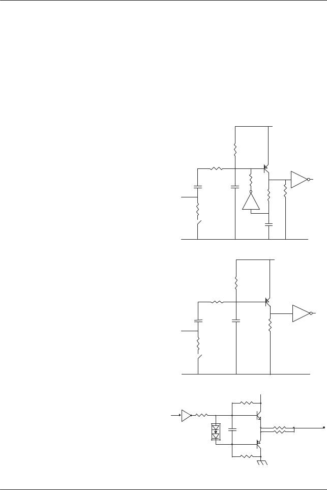
5.4Input and Output Circuits
In the following schematic diagrams the input and output circuits for video and timing signals are shown. For alternative connections refer to “Internal Switch and Jumper Settings”. Jumper settings are shown as for factory default.
5.4.1Video input
The video output signal is a 75Ω RGB video signal. The signal level is 0.7Vpp. Composite sync. is selectable on the green
video signal via software or the internal switch 302-3. The sync. signal level is 0.3Vpp.
+5V
33KB
5.4.2 Trigger input
The trigger input is AC coupled with a flip-flop. The input signal level is 4V ± 2V.
The trigger input impedance is 1.2 kΩ or 75Ω selectable via the internal switch S301-3.
Trigger
input
33KB
SC104V
1K8B
SC102V
100KB
75C
S301-3
SC102V
5.4.3HD and VD input
The HD and VD input circuit can be 75Ω terminated via the internal switch S301-1 and S301-2.
The input signal level is 4V ± 2V.
5.4.4 HD, VD, PCLK, WEN and EEN output
The output circuits for these signals are 75Ω complementary emitter followers. The single circuit delivers a TTL signal. The output level ≥ 4 V from 75Ω (no termination).
+5V
33KB
HD, VD |
SC104V |
1K8B |
|
input |
SC102V |
75C
S301-1(HD),2(VD)
+5V
10KB
220B
TTL
120C
150C
GND
GND
Int VD Int HD PCKL WEN EEN
10KB
- 9 -
Loading...