


OWNER’S MANUAL
Assembly, Installation
& Operating Instructions
TM
J-DREAM II
Shower System

IMPORTANT SAFETY INFORMATION
READ ALL INSTALLATION INSTRUCTIONS
Jacuzzi Whirlpool Bath does not recommend prolonged periods of use of the steamer. Prolonged use of the steam system can raise the internal human body temperature excessively and impair the body's ability to regulate its internal temperature (resulting in hyperthermia). Consult your physician about your safety and comfort before using the steam system; limit your use of steam to 10-15 minutes until you are certain of your body's reaction. A cooling shower spray can be used simultaneously with the steam to assist in regulating your body temperature.
Alcohol, certain drugs or medications such as tranquilizers affect a person's ability to withstand high temperatures and may produce dangerous side effects. Do not use alcohol or drugs when using the J-Dream II.
The elderly, the infirm, and children should not use the J-Dream II unattended. Pregnant women and people with heart conditions should consult their physicians before using the steamer.
The wet surface of the J-Dream II can be slippery. Use care when entering and exiting.
When using the J-Dream II, basic safety precautions should always be followed:
This unit is to be connected to a Ground Fault Circuit Interrupter (GFCI). This is also known as an Earth Leakage Circuit Breaker (ELCB). Check at least once a month to be sure this is operational. With the unit operating, push in the test button. The unit should stop operating and the trip indicator should appear. Restore the power; push to OFF, then turn ON. The unit should now operate normally. If the interrupter fails to operate in this manner, there is a fault in the electrical system or the GFCI and you may not be protected from an electrical shock. Turn off the power and have a qualified electrician check the circuit before using it again.
Do not use electrically connected devices such as television, radio, or stereo speakers, lights, hair dryers, or telephones within 1.5 m (5 feet) of the J-Dream II while in use.
Read manufacturer's safety information with all optional equipment.
Note: This is a professional grade product. A good knowledge of construction techniques, plumbing and electrical installation according to codes are required for proper installation and user satisfaction. We recommend that a licensed contractor perform the installation of all Jacuzzi Whirlpool Bath products. Our warranty does not cover improper installation related problems.
Save These Instructions for Future Use.
Owner's Record
Date Purchased ____________________________________________________________
Purchased From ____________________________________________________________
Installed By ________________________________________________________________
Serial Number ___________________________
(See page 2 for location of serial number.)
Contents
Part I Assembly & Installation
Specifications _______________________________________________________________________ |
2 |
General Information __________________________________________________________________ |
3-4 |
Packaging __________________________________________________________________________ |
5 |
Hardware Identification ________________________________________________________________ |
6 |
Rough-in ___________________________________________________________________________ |
7 |
Base and Drain ______________________________________________________________________ |
8-9 |
Installation of Panels __________________________________________________________________ |
10-16 |
Door Frame _________________________________________________________________________ |
17 |
Top Frame __________________________________________________________________________ |
18 |
Hose and Electrical Connections ________________________________________________________ |
19-21 |
Bonding ____________________________________________________________________________ |
22 |
Final Plumbing ______________________________________________________________________ |
23 |
Front Panels ________________________________________________________________________ |
24 |
Cover ______________________________________________________________________________ |
25 |
Completing the Installation _____________________________________________________________ |
26 |
Part II Operation and Maintenance _______________________________ |
27-30 |
Warranty _____________________________________________________________ |
33-34 |
Inspection and Shipping Claim
Check for shipping damage upon receipt of the J-Dream II. Jacuzzi Whirlpool Bath is not responsible for damage to the J-Dream II sustained during shipping. If damage is evident before unpacking, see instructions regarding shipping claims on the outside of the carton and immediately file a claim with the carrier.
Once the J-Dream II has been removed from the carton and before it is permanently installed, check the parts completely for damage resulting from shipping or handling. All Jacuzzi Whirlpool Bath products are factory tested for proper operation and watertight connections prior to shipping. If problems are detected, immediately notify your Jacuzzi Whirlpool Bath dealer or Authorized Service Agent, or call Jacuzzi Whirlpool Bath, (800) 288-4002, for Warranty Service.
NOTE: Damage or defects which could have been discovered and repaired prior to installation and which are claimed after final installation of the J-Dream II, are excluded from our warranty.
1

J-Dream II Owner's Manual
R
WHIRLPOOL  BATH
BATH
FRONT VIEW
3" (76 mm) CLEARANCE  TO REMOVE DOME
81" |
83" |
(2057mm) |
(2108mm) |
|
60" |
|
(1524 mm) |
TOP VIEW
60"
(1524mm)
11 5/8" SERIAL NUMBER LOCATION (295mm) (AT TOP) ON BACK OF
EQUIPMENT SEAT WALL
21 1/2" (546mm)
42"
(1067mm)
SPECIFICATIONS
|
TOTAL WEIGHT/ |
REQUIRED |
PRODUCT |
ELECTRICAL |
SHIPPING |
DIMENSIONS |
FLOOR LOADING |
WATER SUPPLY |
WEIGHT |
REQUIREMENTS* |
WEIGHT |
60" (1524mm)L |
833 lb (379 kg) |
6 gpm (23 liter/min) |
525 lb |
240 VAC, 3-Wire |
849 lb |
42" (1067mm)W |
47.6 lb/ft2 |
@ 30-65 psi |
(239 kg) |
20 Amp, 50-60 Hz |
(386 kg) |
83" (2108mm)H |
(233 kg/m2) |
(2.1-4.6 Bar) |
|
(Must be GFCI |
|
|
|
|
|
Protected) |
|
* Unit supplied with a 240 VAC, 20 Amp, 3 wire plug (NEMA 6-20P).
PRODUCT SPECIFICATIONS ARE SUBJECT TO CHANGE WITHOUT NOTICE.
2

J-Dream II Owner's Manual
Read all instructions before beginning assembly and installation.
General Assembly Information
The J-Dream II shower unit is installed into a niche with the drain towards the left hand side of the unit as you face the shower door. This manual details the assembly, installation and operation. After the drain, water supply stub-out, and electrical supply are provided, the shower unit should be assembled freestanding away from the walls of the room. Next connect and static test the water supply lines. The electrical connections should then be completed before the unit is moved into final position, drain fit is rechecked, and assembly is completed before final testing.
Room Construction: Important
The room where the shower unit is to be located must be constructed of materials that can withstand excessive amounts of moisture and condensation. Large amounts of steam can be released into the room when the shower door is opened. Providing natural or forced ventilation of the room will help maintain comfort and minimize moisture damage to the building. Jacuzzi Whirlpool Bath is not responsible for damages resulting from excess moisture or water spillage. Consult an architect or engineer for aid in designing your interior structure. Do not install heat lamps directly above the shower unit. The clear top will deform from excess heat.
Water Supply Required
The water supply must be capable of delivering 6 gallons per minute minimum to the unit within a pressure range of 30-65 PSI (2.1-4.6 BAR). Pressures in excess of 65 PSI (4.6 BAR) must be reduced with a regulator in the supply line. This is the amount of water and pressure required to ensure adequate performance of the J-Dream II, it is not the water consumption rate.
NOTE: DO NOT provide less than minimum flow specified. Negative pressure under certain conditions could cause a health hazard by fouling of the house potable water supply.
Electrical Power Required
See Specifications for power required. Power supplied to the unit must be through a *GFCI protected, dedicated circuit with proper bonding and grounding. The GFCI must be located in an area that will allow access for frequent testing.
* GFCI ( Ground Fault Circuit Interrupter) is also known as an ELCB ( Earth Leakage Circuit Breaker.) This device must be a type approved by electrical codes and standards to protect users from potential electrical hazards.
3

J-Dream II Owner's Manual
Electrical requirements
Your J-Dream II, as it comes from the factory, requires a GFCI protected 240 VAC 3- wire 20 AMP 50-60 Hz circuit (2 conductor with ground) for single (1) phase electrical service, and must be in a separate circuit having no other appliance connected in that circuit. If you do not have this kind of circuit, a qualified electrician should be called in to install the necessary wiring. Inadequately sized wiring or locating the unit too far from the main service panel may cause a voltage drop. A drop in voltage can cause the unit to malfunction and bring about permanent damage to the shower's electrical system. The circuit ground wire must be provided to take advantage of the designed-in safety features of the J-Dream II. Bond according to procedure described on page 23. Caution: Without proper grounding and bonding, a system malfunction may cause fatal shock.
Electrical precautions
Lighting and electrical receptacles must be located at least 5 feet (1.5 meters) from the J-Dream II. Lighting located between 5 feet and 10 feet (1.5 meters and 3 meters) from the J-Dream II must be on a circuit protected by a GFCI. Do not use electrically connected devices, such as television, radio, telephones, stereo speakers, lights or cooking devices within 5 feet of the J- Dream II while it is in use.
Ventilation
Water which drips on the floor during exit from the J-Dream II may cause a walking hazard and/or structural damage unless proper waterproof building materials are used in the area surrounding the unit. Take into consideration, also, the high room humidity which will exist due to use of the steamer. Providing natural or forced ventilation of the room will help maintain comfort and minimize moisture damage to the building. Jacuzzi Whirlpool Bath is not responsible for damages resulting from excess moisture or water spillage. Consult an architect or engineer for aid in designing your installation.
Maintenance
Cleaning the J-Dream II
To clean your J-Dream II, simply use a mild nonabrasive liquid detergent or commercially prepared bathtub cleaners. Do not use abrasive cleaners. You can protect and restore the gloss to a dulled surface by applying a plastic polish specifically designed for use on acrylic finishes (methylmethacrylate). If an acrylic polish is not available, an automotive paste wax will do.
Repairs to the surface
Minor scratches which do not penetrate the color finish (acrylic) can be removed with 600-grit wet/dry sandpaper. Restore the glossy finish with an acrylic polish or a comparable automotive paste wax.
Major scratches or gouges which penetrate the acrylic surface will require refinishing. Ask your dealer for special instructions.
4

J-Dream II Owner's Manual
J-Dream II Packaging
6 cartons packed together on a wooden crate.
Contents of cartons:
•Wall Panels
•Door Frame
•Base/Cover (includes product accessory pack and owners manual)
•Back Wall
•Seat Wall
•Equipment/Seat Wall
5

J-Dream II Owner's Manual
Letters (A) are used in the illustrations of the assembly procedure.
A CLIP
B SCREW
C WASHER
D NUT
E SCREW
F SCREW
G BOLT
H BOLT
I WASHER
U-CLIP 10-24
PAN HEAD SCREW #10-24 x 3/4"
FLAT WASHER 1/4"
LOCK NUT 10-24
FLAT HEAD SCREW
M4x10mm
PAN HEAD SCREW #12 x 1/2
HEX BOLT 1/4-20 x 1.5"
SELF-TAPPING
M6x50mm
EXTERNAL TOOTH LOCK-WASHER 1/4
JNUT
KWASHER
L SCREW
SIDE BRACKET
L BRACKET
LAG SCREW
CLAMP
1/4-20 LOCK NUT
FLAT WASHER #10
PAN HEAD SCREW #6-32 x .38
6

J-Dream II Owner's Manual
Rough-in
HOSE
BIBB (2)
(2) 1/2 " HOT & COLD WATER SUPPLY LINES
IMPORTANT: This is the installed position of the waste stub-out when connected to the shower drain. If the stub-out is installed before the shower unit, leave enough flex in the waste line to allow the end of the stub-out to be blocked temporarily (see page 10) in a position under flush to the floor surface. This will allow the shower unit to slide across the floor into position without having to lift it.
IMPORTANT: The shower drain is designed to connect to a 2 inch (50mm) ABS or PVC (as approved by local codes/standards) waste stubout.
End of 2 inch (50 mm) waste stubout must be located to these dimensions within 1/4 inch (6mm).
21-1/2"
11-5/8"
FINISHED WALL
SURFACE
WASHING
MACHINE 37" OUTLET
BOX
FINISHED
WALLS
42"
FINISHED FLOOR
MATERIAL
2 " WASTE STUBOUT
CONNECT #8 GAUGE (10mm2) MINIMUM SOLID COPPER BOND WIRE TO THE HOUSE ELECTRICAL PANEL OR APPROVED LOCAL GROUND. AN APPROVED GROUND MAY BE AN 8 FOOT LONG GROUND ROD (3 METER LONG EARTH ROD), A PLATE ELECTRODE, OR OTHER ACCEPTABLE BOND. CHECK YOUR LOCAL BUILDING CODE FOR REQUIREMENTS. (SEE PAGE 22 FOR BONDING INSTRUCTIONS).
ELECTRICAL OUTLET 3 WIRE 240V 20A RATING TO BE ON A GFCI PROTECTED CIRCUIT
55 "
40 "
FINISHED WALL
SURFACE
60" FINISHED MINIMUM
7
J-Dream II Owner's Manual
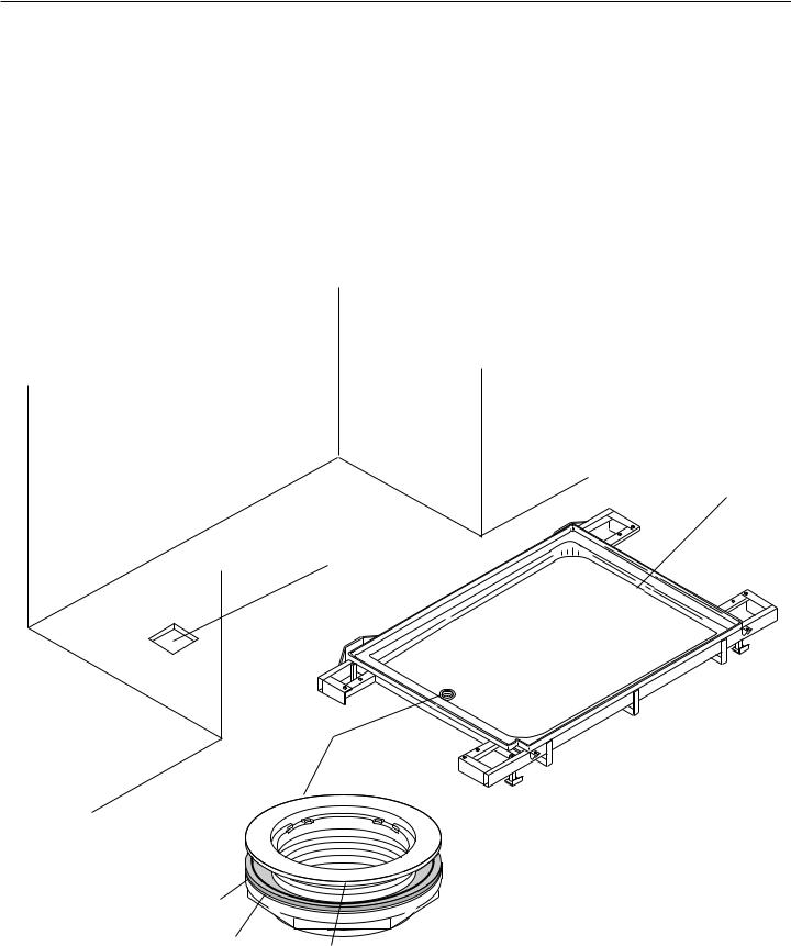
Locate Base to provide assembly access to all sides
Remove Base from carton labeled Base/Top. Place Clear Top in carton to prevent damage. (The Clear Top will not be installed until the unit has been fully assembled and plumbed).
Position the J-Dream base on the floor so that you have work access to all four sides of the unit during assembly. (Allow a minimum of 24" (600 mm) of access on each side of base.) Before starting assembly, position the base pointing in the same direction as it will be in the final installation position so no unnecessary turning of the unit is required.
Niche where J-Dream II is to be finally installed.
Notice Base is positioned in the same direction as it will be in the final installation position.
Base
Floor cut-out for drain pipe.
Drain Fitting
Silicone
Sealant
RubberWasher
Flange
8
J-Dream II Owner's Manual
Drain Fitting (provided with unit)
Leave enough flexibility in the waste line to allow the end of the stub-out to be blocked temporarily in a position under flush with the floor surface. This will allow the shower unit to slide across the floor into position without having to lift the shower unit.
Studwall
Temporary
Wood Block Drain
Compression
Fitting
Floor |
Drain Assembly |
Remove the block and pull the drain assembly up to insert the stub into the drain. The drain fitting is a non-caulk type (compression fitting) drain. Make certain that the locking ring is loose to allow the drain stub to insert easily inside the rubber compression sleeve. If necessary, lubricate the sleeve with a mild soap solution. The drain stub must extend well into the rubber sleeve before the locking ring is tightened. Use a screwdriver and the assembly tool provided to tighten the locking ring.
Screwdriver
Assembly Tool
Locking
Ring Tighten
Locking Ring
Clockwise
Broken Line |
Rubber |
Represents |
|
Drain Stub |
Compression |
|
Sleeve |
9
 Loading...