


Rollators
Assembly, Installation and Operating Instructions
Model No. 65900 |
Model No. 65800 |
Model No. 65700 |
|
|
|
|
|
|
SAVE THESE INSTRUCTIONS
NOTE: Check ALL parts for shipping damage. In case of damage, DO NOT use. Contact Carrier/Dealer for further instruction.
SAFETY SUMMARY
The following recommendations are made for the safe use of the Rollators:
GENERAL WARNINGS
DO NOT install or use this equipment without first reading and understanding this instruction sheet. If you are unable to understand the Warnings, Cautions or Instructions, contact a healthcare professional, dealer or technical personnel before attempting to install this equipment - otherwise, injury or damage may occur.
Models 65700 and 65800 are NOT to be pushed while seated and/or used as a wheelchair.
Rollators are NOT intended to be self propelled while seated.
When using the transport feature of model 65900, an attendant MUST be present.
The transport feature of model 65900 is intended for use during periods of fatigue and/or resting. It is NOT intended as a replacement for a wheelchair. The transport feature may ONLY be used for short distances over smooth level surfaces - otherwise, injury or damage may occur.
DO NOT use the transport feature of model 65900 on a ramp or incline - otherwise, injury or damage may occur.
A physical/occupational therapist should assist in the placement and positioning of the push handles for maximum support and correct brake activation.
Care should be taken to ensure that ALL hand and height adjustments are secure, and that casters and moving objects are in good working order before using this or any mobility aid.
All wheels MUST be in contact with the floor at ALL TIMES during use. This will ensure the rollator is properly balanced.
The brakes MUST be in the locked position BEFORE using the seat.
Model 65700 only - Check crutch tips for rips, tears, cracks or wear. If any of these conditions exist, replace crutch tips immediately.
MODEL 65900 ONLY - DO NOT step or stand on the footrests when entering or exiting the rollator.
GENERAL WARNINGS CONTINUED
The Rollator basket has a weight limitation of 15 lbs. (6 kg.).
The Rollator can provide ambulatory assistance to an individual weighing up to 300 lbs. (136.08 kg) for model 65900, and 250 lbs. (113.4 kg) for models 65800 and 65700, INCLUDING the weight of the contents of the basket.
INSTALLATION WARNINGS
ALWAYS test to see that the rollator is properly and securely locked in the open position BEFORE using.
After installation and BEFORE use, ensure that ALL attaching hardware is securely tightened.
STABILITY WARNINGS
DO NOT attempt to reach objects if you have to move forward in the seat. Reaching for these objects will cause a change to the weight distribution of the rollator and may cause the rollator to tip, resulting in injury or damage.
BEFORE attempting to reach objects or pick them up from the floor by reaching down between your knees, place feet securely on the floor. Use EXTREME caution when reaching for any object.
OPENING/FOLDING THE ROLLATOR
NOTE: Refer to INSTALLATION WARNINGS in the SAFETY SUMMARY in this instruction sheet.
Opening the Rollator (FIGURE 1)
1.Remove the rollator from the carton.
2.Hold seat handle and push down on seat until an audible “click” is heard.
3.MODELS 65800 AND 65700 ONLY: If necessary, install the backrest. Refer to REMOVING/ INSTALLINGTHEBACKRESTinthisinstructionsheet.
4.Install backrest pad. Refer to REMOVING/ INSTALLING THE BACKREST PAD in this instruction sheet.
5.Install push handles. Refer to INSTALLING/ ADJUSTING THE PUSH HANDLES in this instruction sheet.
1
Folding the Rollator (FIGURE 1)
1. Hold seat handle and pull up.
NOTE: Model 65900 shown ONLY. Models 65800 and 65700 will open/fold the same way.
Seat
Seat Handle
FIGURE1-OPENING/FOLDINGTHEROLLATOR
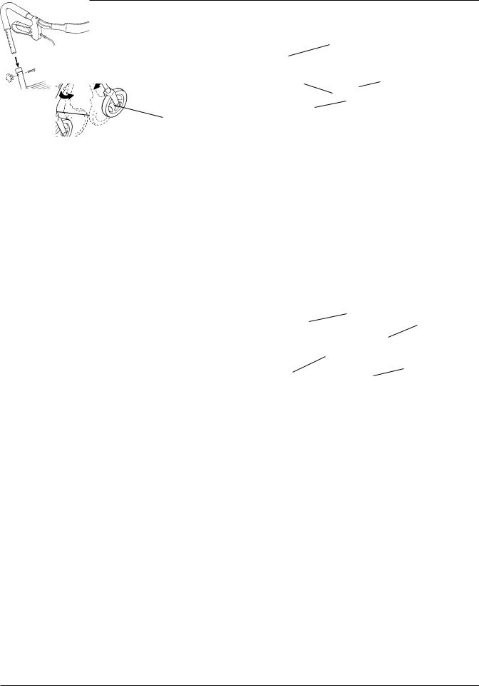
INSTALLING/ADJUSTING THE PUSH HANDLES (FIGURE 2)
NOTE: Refer to INSTALLATION WARNINGS in the SAFETY SUMMARY in this instruction sheet.
Installing the Push Handles
1.Removeadjustmentknobsandscrewsfrombothsides of the frame by turning COUNTERCLOCKWISE.
2.InsertpushhandlesintoframesasshowninFIGURE2.
3.RefertoADJUSTINGTHEPUSHHANDLESinthisprocedure of the instruction sheet.
Adjusting the Push Handles
NOTE: When making this adjustment, ensure the user’s shoe height is the same as shoe style worn most frequently when using the rollator. This will provide the most comfortable push handle position.
1.Position the push handle so that when the user’s arm is down to their side, the hand grip is at wrist height.
NOTE: This will ensure the arms are at an approximate 20o - 30o bend when using the rollator.
2.Install screw into one (1) of the six (6) adjustment holes.
3.SecurewithadjustmentknobbyturningCLOCKWISE.
4.Repeat STEPS 1 - 3 for the other side.
5.Securely tighten.
NOTE:Whensecurelytightened,thepushhandlesshould not move.
Push
Handle
Adjustment |
Screw |
Knob |
|
Frame |
|
FIGURE2-INSTALLING/ADJUSTINGTHEPUSH
HANDLES
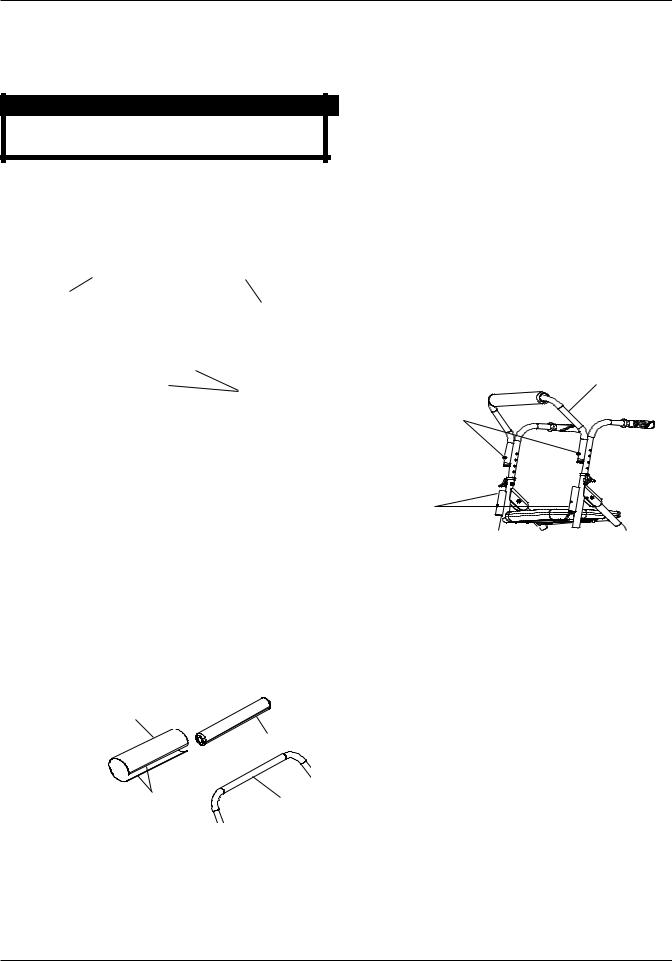
INSTALLING THE BASKET
NOTE: Refer to INSTALLATION WARNINGS in the SAFETY SUMMARY in this instruction sheet.
Models 65900, 65800 and 65700 (FIGURE 3)
1.Install basket between the seat support tube and the support tube so the hooks are on the seat support tube as shown in FIGURE 3.
Hooks |
Seat |
|
|
|
Support |
|
Tube |
Basket |
Support |
Tube |
NOTE: Model 65900 shown.
FIGURE3-INSTALLINGTHEBASKET-MODELS
65900, 65800 AND 65700
2
INSTALLING THE TRAY (FIGURE 4)
NOTE: Refer to INSTALLATION WARNINGS in the SAFETY SUMMARY in this instruction sheet.
CAUTION
DO NOT sit on the seat with the tray installed, damage to the tray may occur.
1.Align the four (4) pins on the bottom of the tray with the four (4) holes in the seat.
2.Push down on tray to secure in place.
Tray
Pins
Seat 
Holes
FIGURE 4 - INSTALLING THE TRAY
REMOVING/INSTALLING THE BACK SUPPORT PAD - MODELS 65900, 65800 AND 65700 (FIGURE 5)
NOTE: Refer to INSTALLATION WARNINGS in the SAFETY SUMMARY in this instruction sheet.
1.Seperate the hook and latch strips and remove the back pad cover.
2.Remove the EXISTING back pad from the backrest.
3.Slide the NEW back pad over the backrest.
4.Reinstall the back pad cover and secure with hook and latch strips.
Back Pad Cover
Back Pad
NOTE: Model
65800shown
Hook and Latch |
Backrest |
Strips |
|
FIGURE5-REPLACINGTHEBACKSUPPORTPAD - MODELS 65900, 65800 AND 65700 ONLY
REMOVING/INSTALLING THE BACKREST - MODELS 65800 AND 65700 ONLY (FIGURE 6)
NOTE: Refer to INSTALLATION WARNINGS in the SAFETY SUMMARY in this instruction sheet.
Removing the Backrest
1.Depress both the two (2) snap buttons and pull UP to removethebackrestfromthebackrestsupporttubes.
Installing the Backrest
1.Insert the backrest into the two (2) backrest support tubes.
2.Ensurethetwo(2)snapbuttonsfullyprotrudethrough the mounting holes of the backrest support tubes.
Backrest
Snap Buttons
Backrest Support
Tubes
FIGURE6-REMOVING/INSTALLINGTHE BACKREST - MODELS 65800 AND 65700 ONLY
3
 Loading...