


 Loading...
IMB200
Intel® PentiumD/Pentium4/Celeron D
Industrial ATX Motherboard
User’s Manual
Disclaimers
The information in this manual has been carefully checked and is believed to be accurate. AXIOMTEK Co., Ltd. assumes no responsibility for any infringements of patents or other rights of third parties which may result from its use.
AXIOMTEK assumes no responsibility for any inaccuracies that may be contained in this document. AXIOMTEK makes no commitment to update or to keep current the information contained in this manual.
AXIOMTEK reserves the right to make improvements to this document and/or product at any time and without notice.
No part of this document may be reproduced, stored in a retrieval system, or transmitted, in any form or by any means, electronic, mechanical, photocopying, recording, or otherwise, without the prior written permission of AXIOMTEK Co., Ltd.
©Copyright 2006 by AXIOMTEK Co., Ltd.
All rights reserved. Aug 2006, Version A1
ii
ESD Precautions
Integrated circuits on computer boards are sensitive to static electricity. To avoid damaging chips from electrostatic discharge, observe the following precautions:
Do not remove boards or integrated circuits from their anti-static packaging until you are ready to install them.
Before handling a board or integrated circuit, touch an unpainted portion of the system unit chassis for a few seconds. This helps to discharge any static electricity on your body.
Wear a wrist-grounding strap, available from most electronic component stores, when handling boards and components.
Trademarks Acknowledgments
AXIOMTEK is a trademark of AXIOMTEK Co., Ltd.
IBM is a registered trademark of International Business Machines Corporation.
MS-DOS, and Windows 2000 are trademarks of Microsoft Corporation.
Award is a trademark of Award Software, Inc.
IBM, PC/AT, PS/2, VGA are trademarks of International Business Machines Corporation.
Intel Pentium D, Pentium4, Celeron D is trademarks of Intel Corporation.
Other brand names and trademarks are the properties and registered brands of their respective owners.
iii
|
T a b l e o f C o n t e n t s |
|
Disclaimers .................................................................... |
ii |
|
ESD Precautions ........................................................... |
iii |
|
Chapter |
1 Introduction........................................................ |
1 |
1.1 |
General Description ............................................. |
1 |
1.2 |
Specifications ...................................................... |
2 |
1.3 |
Utilities Supported................................................ |
3 |
1.4 |
Ordering information ............................................ |
3 |
1.4 |
Board Dimensions ................................................ |
4 |
Chapter 2 Jumpers and Connectors .................................... |
5 |
|
2.1 |
Board Layout ....................................................... |
5 |
2.2 |
Jumper Settings ................................................... |
6 |
2.2.1Watchdog Tigger Mode: JP2……………………….. 6
2.2.2COM1 RS232/422/485 Settings: JP4, JP5,JP6….. 7
2.2.3Clear CMOS Setting: JP7…………………………… 7
2.2.4CF Master/Slave Setting: JP8………………………. 7
2.2.5CF Power Setting: JP9………………………………. 8
2.3 |
Connectors .......................................................... |
9 |
Chapter 3 Installation ........................................................ |
11 |
|
3.1 |
CPU Installation .................................................... |
11 |
3.2Installing ATX Power Supply………………………….. 18 |
||
3.3 |
Installing the Memory ............................................. |
18 |
Chapter 4 Hardware Description ....................................... |
20 |
|
4.2 |
Enhane IDE1/IDE2 connecotor-IDE1 and IDE2 ........ |
21 |
4.3 |
Display interface-CN1............................................. |
22 |
4.4 |
Floppy Disck Connector-FDD .................................. |
22 |
4.5 |
Parallel Port Connector .......................................... |
23 |
4.6 |
COM1 Port Connector-CN2..................................... |
24 |
4.7 COM2/3/4 Port Connector-CN25/CN27/CN33 support |
||
RS232 ......................................................................... |
25 |
|
4.8 |
USB and Giagbit LAN RJ-45 Connector-CN6........... |
25 |
4.9 |
USB and 10/100Mb LAN RJ-45 Connector-CN7....... |
26 |
4.10 USB Connector by pin header-CN30 ..................... |
26 |
|
iv |
|
|
4.11 Audio Jack (Line-in/Line-Out/MIC)-CN3................. |
27 |
|
4.12 ATX12V CPU Power Connector: CN14 .................. |
27 |
|
4.13 Serial ATA Connectors-CN28/CN29 ...................... |
28 |
|
4.14 PS/2 Keyboard/Mouse connector-CN4 .................. |
29 |
|
4.15 Digital I/O Connector-CN38 .................................. |
29 |
|
4.16 CD/In Connector-CN9 ........................................... |
30 |
|
4.17 CPU/System FAN Connector-CN23/CN24 ............. |
31 |
|
Chapter 5 Installing VGA driver......................................... |
32 |
|
5.1 |
Introduction........................................................ |
32 |
5.2 |
Driver Disks’ Contents........................................ |
32 |
5.3 |
Windows 2000 VGA Driver Installation................ |
32 |
5.4 |
Windows XP VGA Driver Installation ................... |
34 |
Chapter |
6 Installing LAN Driver........................................ |
35 |
6.1 |
Introduction........................................................ |
35 |
6.3 |
Drivers Supported .............................................. |
35 |
Chapter |
7 Award BIOS Utility ........................................... |
36 |
7.2 |
BIOS Setup ........................................................ |
36 |
7.3 |
Standard CMOS Setup ....................................... |
38 |
7.4 |
Advanced BIOS Features ................................... |
41 |
7.4.1CPU Feature…………………………………………. 41
7.4.2Hard Disk Boot Priority……………………………… 43
7.5 |
Advanced Chipset Features................................ |
46 |
7.6 |
Integrated Peripherals ........................................ |
50 |
7.6.1On-Chip IDE Device………………………………… 50
7.6.2Onboard Device……………………………………. 52
7.6.3Super IO Device……………………………………. 54
7.7 |
Power Management Setup.................................. |
57 |
|
7.8 |
PNP/PCI Configuration ....................................... |
60 |
|
7.9 |
PC Health Status ............................................... |
62 |
|
7.10 |
Frequency/Voltage Control ................................. |
63 |
|
7.11 |
Load Fail-Safe Default .......................................... |
64 |
|
7.12 |
Load Optimized Default ........................................ |
64 |
|
7.13 |
Supervisor/User Password Setting ........................ |
64 |
|
7.14 |
Exit Setting........................................................... |
66 |
|
A p p e n d i x A |
Watchdog Timer .................................... |
68 |
|
A p p e n d i x B |
PCI IRQ Routing ..................................... |
69 |
|
|
PICMG PCI IRQ Routing................................ |
69 |
|
|
|
|
v |
|
On Board Device IRQ Routing ....................... |
69 |
AppendixC |
Detailed memory Addess Mapping ................ |
70 |
AppendixD |
I/O Shield........................................................ |
71 |
vi
IMB200 LGA775 ATX MB User Manual
Chapter 1 Introduction
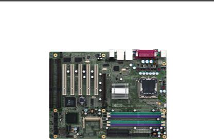
1.1General Description
The IMB200 supports LGA775-pin Intel® Pentium® D (Intel Dual-Core) processor up to 3.6GHz with a 533/800MHz front side bus (FSB), and features an Intel® 865G + ICH*5 chipset. With Intel dual-core processing technology, the IMB200 provides the excellent performance to handle multitasking and to run multiple applications simultaneously. The IMB200 is specially suited for the solutions which need more effective computing and reliability, such as Digital Video Recorder/Gamine Machine/Point of Service System/Video Server/Intelligent Transmit System and so on.
Introduction |
1 |

IMB200 LGA775 ATX MB User Manual
1.2Specifications
¾Processor: Intel® Pentium D/Pentium4/Celeron
¾North Bridge: Intel® 82865G
¾South Bridge: Intel® 82801EB(ICH5)
¾CPU Socket: LGA775
¾FSB: 533/800 Mhz
¾L2 Cache: Integrated in CPU(Depend on CPU)
¾BIOS: Phoenix Award BIOS Rev.6.00
¾System Memory: Support Dual Channel DDR 266/333/400 memory and the maximum capacity up to
4GB.
CPU FSB |
DDR Type |
DDR Frequency |
|
|
|
800MHz |
PC3200/PC2700/PC2100 |
400/333*/266MHz |
533MHz |
PC2700/PC2100 |
333/266MHz |
*Because limited of chipset, when using FSB800Mhz CPU, PC2700 DDR (333 MHz) only supports 320 MHz.
¾IDE Interface: Two IDE connector and up to four devices, Ultra DMA 100 supported
¾FDD Interface: Supports up to 2 drives
¾Serial Ports: RS232/422/485 Portx1,RS232 Portx3
¾Parallel Ports: One parallel port with ECP/EPP/SPP supported
¾VGA Controller:
¾Chipset Integrated VGA Controller and Supports up to 2048x1536 at 75 Hz resolution on non-interlaced CRT monitors
¾Ethernet: Intel82547GI/Intel82562ET
¾SATA: Two Channel and support the maximum data transfer rate could up to 150MB/s
2 |
Introduction |

IMB200 LGA775 ATX MB User Manual
¾CF Socket: Support CF Type II Socket
¾USB Interface: 4 USB ports; USB Spec. Rev. 2.0 compliant.
¾Hardware Monitoring: Winbond W83627HG-AW detection of CPU temperature, System temperature, Power failure and Fan speed.
¾Watchdog Timer:
Software programmable time interval and hardware reset Only (1~255 seconds)
¾Dimensions:304.8mmx243.8mm(4 Layer)-ATX Former
¾Environmental:
Operating temperature |
0 degrees to 60 degrees(Depends on CPU) |
CPU Relative Humidity |
95% |
NOTE: Specifications are subject to change without notice.
1.3Utilities Supported
zIntel® 865G Utility and Drivers
zEthernet Utility and Drivers
zVGA Drivers
zAudio Driver
1.4Ordering information
Model number |
Description |
IMB200VGE |
Intel547GI/Intel82562ET LAN |
IMB200VG |
Intel547GI |
Introduction |
3 |
IMB200 LGA775 ATX MB User Manual
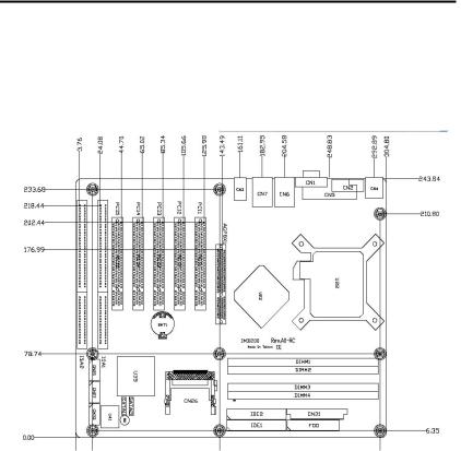
1.4Board Dimensions
4 |
Introduction |

IMB200 LGA775 ATX MB User Manual
Chapter 2 Jumpers and Connectors
2.1Board Layout
Jumpers and Connectors |
5 |
IMB200 LGA775 ATX MB User Manual
2.2Jumper Settings
Followed as below detailed description for Jumper setting and installed the IMB200 for your application
Jumper |
Default Setting |
Jumper Setting |
|
||
|
|
|
JP2 |
Watchdog Trigger Mode : |
OPEN |
|
Disable |
Short 1-2 for NMI |
|
|
Short 2-3 for Reset |
JP4 |
|
Short 3-5,4-6(Default) |
|
|
Short 1-3 , 2-4 for |
|
|
RS422/485 |
JP5 |
|
Short 1-2 ,7-8(Default) |
|
|
Short 3-4 , 7-8 for RS422 |
|
Com 1 RS232/422/485 Setting |
Short 5-6 , 7-8 for RS485 |
JP6 |
|
Short 3-5,4-6(Default) |
|
|
Short 1-3 , 2-4 for |
|
|
RS422/485 |
JP7 |
CMOS Clear Jumper : Normal |
Short 1-2 for Normal |
|
Mode |
Short 2-3 for Clear |
JP8 |
Compact Flash Master/Slave : |
Short for Master |
|
Master |
Open for Slave |
JP9 |
Compact Flash Power Select : |
Short 1-2 for 3.3V |
|
3.3V |
Short 2-3 for 5V |
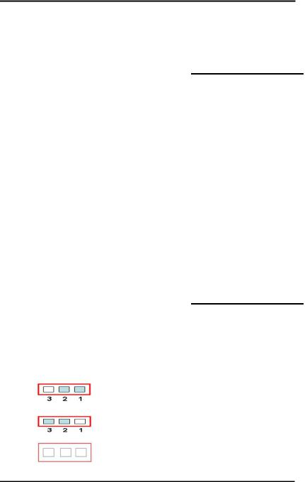
2.2.1 Watchdog Trigger Mode: JP2
|
Options |
Settings |
|
|
|
|
NMI |
1-2 |
|
|
|
|
RESET |
2-3 |
|
|
|
|
Disabled |
Open (Default) |
|
|
|
6 |
Jumpers and Connectors |
IMB200 LGA775 ATX MB User Manual
2.2.2 COM1 RS232/422/485 Settings: JP4, JP5, JP6
COM1 |
JP4 |
JP5 |
JP6 |
|
RS-232 |
Short 3-5,4-6 |
Short 1-2,7-8 |
Short 3-5,4-6 |
|
(Default) |
||||
|
|
|
||
RS-422 |
Short 1-3,2-4 |
Short 3-4,7-8 |
Short 1-3,2-4 |
|
|
||||
RS-485 |
Short 1-3,2-4 |
Short 5-6,7-8 |
Short 1-3,2-4 |
|
|
2.2.3 Clear CMOS Setting: JP7
|
Options |
Settings |
|
|
|
|
Normal |
1-2(Default) |
|
|
|
|
Clear CMOS |
2-3 |
|
|
|
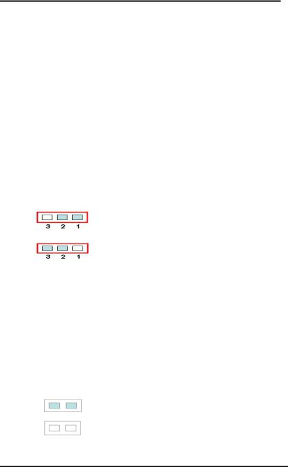
2.2.4 CF Master/Slave Setting: JP8
|
Options |
Settings |
|
|
|
|
Master |
Short(Default) |
|
Slave |
Open |
Jumpers and Connectors |
7 |
IMB200 LGA775 ATX MB User Manual
2.2.5 CF Power Setting: JP9
|
Options |
Settings |
|
|
|
|
3.3V |
1-2(Default) |
|
|
|
|
5V |
2-3 |
|
|
|
8 |
Jumpers and Connectors |

IMB200 LGA775 ATX MB User Manual
2.3 Connectors
The following table lists the function of each connector on the IMB200.
Connectors |
Label |
Connectors |
Label |
General Output |
CN37 |
Primary IDE |
IDE1 |
Connector |
|
Connector |
|
Printer Port Connector |
CN5 |
Secondary IDE |
IDE2 |
|
|
Connector |
|
COM1 |
CN2 |
Compact Flash |
CN26 |
|
|
Connector |
|
COM2 |
CN33 |
S-ATA Port 1 |
SATA |
|
|
Connector |
1 |
COM3 |
CN25 |
S-ATA Port 2 |
SATA |
|
|
Connector |
2 |
COM4 |
CN27 |
FDD Connector |
FDD |
USB Port 1, 2 Connector |
CN6 |
IrDA Connector |
CN12 |
USB Port 3, 4 Connector |
CN7 |
CPU FAN Connector |
CN23 |
USB Port 5, 6 Connector |
CN30 |
SYSTEM FAN1 |
CN36 |
|
|
Connector |
|
System BIOS |
U41 |
SYSTEM FAN2 |
CN24 |
|
|
Connector |
|
CRT Connector |
CN1 |
Internal Buzzer |
BU1 |
Keyboard/Mouse |
CN4 |
Internal Battery |
BAT1 |
Connector |
|
|
|
Gigabit Ethernet |
CN6 |
Audio Jack |
CN3 |
Connector |
|
|
|
Fast Ethernet Connector |
CN7 |
AUX Input |
CN8 |
|
|
Connector |
|
Gigabit Ethernet |
CN13 |
CD Input Connector |
CN9 |
External Speed LED |
|
|
|
Fast Ethernet |
CN17 |
Speaker Output |
CN10 |
External Speed LED |
|
Connector |
|
Gigabit Ethernet External |
CN16 |
184-Pin DDR |
DIMM |
Link/ACT LED |
|
Memory Channel-A |
1/2 |
Fast Ethernet |
CN15 |
184-Pin DDR |
DIMM |
External Link/ACT LED |
|
Memory Channel-B |
3/4 |
ATX12V CPU Power |
CN14 |
ISA Slot |
ISA1/ |
Connector |
|
|
2 |
Jumpers and Connectors |
9 |

IMB200 LGA775 ATX MB User Manual
Connectors |
Label |
Connectors |
Label |
|
ATX Power Connector |
CN31 |
PCI Slot |
PCI1~ |
|
|
|
|
5 |
|
LGA775 CPU Socket |
U22 |
AGP Slot |
AGP8 |
|
|
|
|
X1 |
|
DIO Connector |
CN38 |
|
|
|
10 |
Jumpers and Connectors |
IMB200 LGA775 ATX MB User Manual
Chapter 3 Installation
Before installing the processor, Please pay more attention on Intel website and obtained more information
http://www.intel.com.
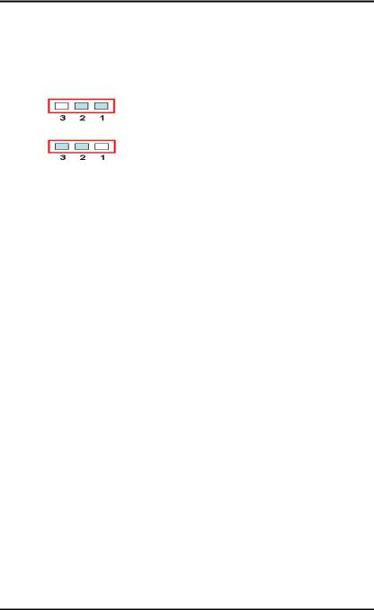
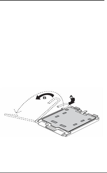
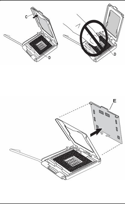
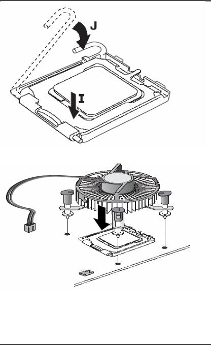
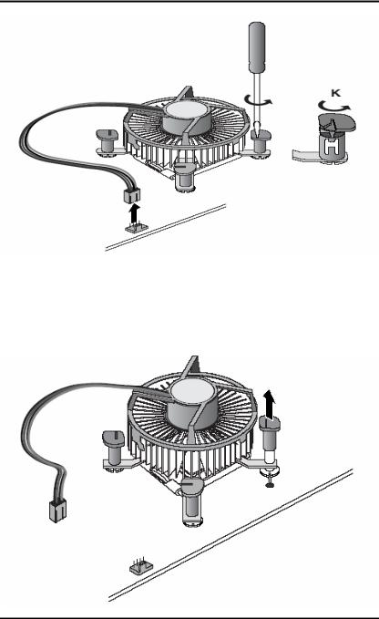
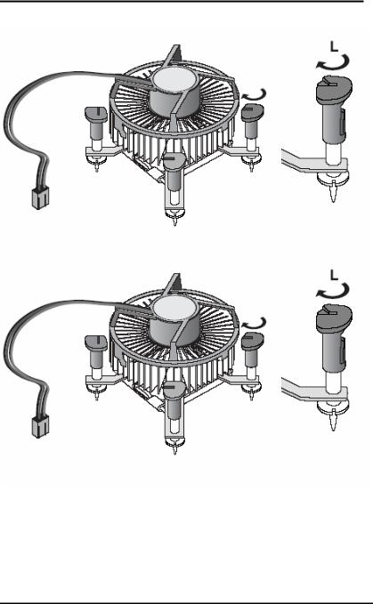
3.1 CPU Installation
The LGA775 processor socket comes with a lever to protect the processor. Please pay more attention as below. Follow the pictures and place the processor into CPU socket.
.
Installation |
11 |
IMB200 LGA775 ATX MB User Manual
.
12 |
Installation |

IMB200 LGA775 ATX MB User Manual
Installation |
13 |
IMB200 LGA775 ATX MB User Manual
14 |
Installation |
IMB200 LGA775 ATX MB User Manual
Installation |
15 |
IMB200 LGA775 ATX MB User Manual
16 |
Installation |
IMB200 LGA775 ATX MB User Manual
Installation |
17 |
IMB200 LGA775 ATX MB User Manual
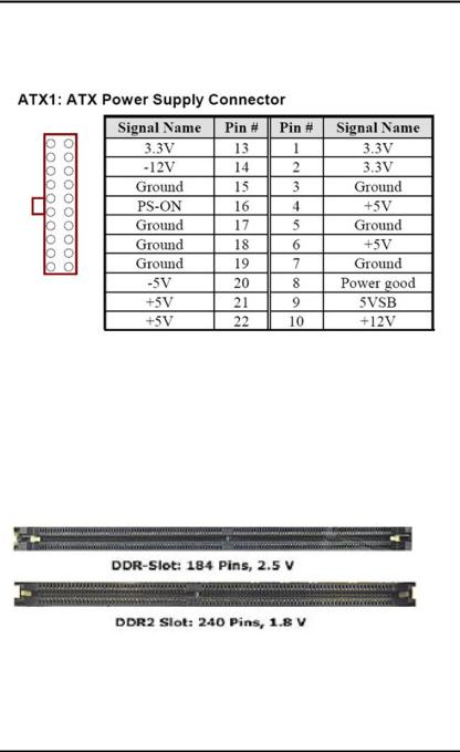
3.2Installing ATX Power Supply
System power was provided for the IMB200 Industrial motherboard by CN31
3.3 Installing the Memory
The IMB200 support Dual Channel DDR 266/333/400 memory and support the maximum memory capacity could up to 4GB.
If you want to know what is difference between DDR and DDR2.See below picture
PS: IMB200 only support Un-Buffered DIMM and could not support ECC/Registered DIMM
18 |
Installation |
Loading...