


F u l l-size CPU Card |
F S B - 8 6 5 G |
|
|
FSB-865G
Intel® Pentium® 4 &
Celeron® Processors
Full-size CPU Card
With DDR, Ethernet,
CompactFlash™ & Mini PCI
FSB-865G Rev. A Manual 2nd Ed.
Dec. 2004
F u l l-size CPU Card |
F S B - 8 6 5 G |
|
|
Copyright Notice
This document is copyrighted, 2004. All rights are reserved. The original manufacturer reserves the right to make improvements to the products described in this manual at any time without notice.
No part of this manual may be reproduced, copied, translated, or transmitted in any form or by any means without the prior written permission of the original manufacturer. Information provided in this manual is intended to be accurate and reliable. However, the original manufacturer assumes no responsibility for its use, or for any infringements upon the rights of third parties that may result from its use.
The material in this document is for product information only and is subject to change without notice. While reasonable efforts have been made in the preparation of this document to assure its accuracy, AAEON assumes no liabilities resulting from errors or omissions in this document, or from the use of the information contained herein.
AAEON reserves the right to make changes in the product design without notice to its users.
i
F u l l-size CPU Card |
F S B - 8 6 5 G |
|
|
Acknowledgments
All other product s’name or trademarks are properties of their respective owners.
•Award is a trademark of Award Software International, Inc.
•CompactFlash™ is a trademark of the Compact Flash Association.
•Intel® , Pentium® M, and Celeron® M are trademarks of Intel® Corporation.
•Microsoft Windows® is a registered trademark of Microsoft Corp.
•ITE is a trademark of Integrated Technology Express, Inc.
•IBM, PC/AT, PS/2, and VGA are trademarks of International Business Machines Corporation.
•SoundBlaster is a trademark of Creative Labs, Inc.
ii
F u l l-size CPU Card |
F S B - 8 6 5 G |
|
|
Packing List
Before you begin installing your card, please make sure that the following materials have been shipped:
∙1 FSB-865G CPU Card
∙1 Floppy Cable
∙1 ATA-100 Cable
∙1 USB Cable
∙1 KB Cable
∙1 Serial + Parallel Cable
∙1 Serial Cable
∙1 ATX Cable
∙1 Quick Installation Guide
∙1 CD-ROM for manual (in PDF format) and drivers
If any of these items should be missing or damaged, please contact your distributor or sales representative immediately.
iii

F u l l-size CPU Card F S B - 8 6 5 G
|
Contents |
|
Chapter 1 General Information |
|
|
1.1 |
Introduction .................................................................................. |
1-2 |
1.2 |
Feature ........................................................................................... |
1-4 |
1.3 |
Specification .................................................................................. |
1-5 |
Chapter 2 Quick Installation Guide |
|
|
2.1 |
Safety Precaution .......................................................................... |
2-2 |
2.2 Location of Connector and Jumper ........................................... |
2-3 |
|
2.3 |
Mechanical Drawing..................................................................... |
2-5 |
2.4 |
List of Jumpers ............................................................................. |
2-7 |
2.5 |
List of Connectors ........................................................................ |
2-8 |
2.6 |
Setting Jumpers ............................................................................. |
2-10 |
2.7 Clear CMOS (JP1) ........................................................................ |
2-11 |
|
2.8 |
LCD Voltage Selection (JP2) ...................................................... |
2-11 |
2.9 |
Front panel Connector (FP1) ...................................................... |
2-11 |
2.10 Front panel Connector (FP2) .................................................... |
2-12 |
|
2.11 TV-Out Connector (TV1) ......................................................... |
2-12 |
|
2.12 RS-232 Serial Port Connector (COM1) ................................... |
2-12 |
|
2.13 RS-232/422/485 Serial Port Connector (COM2) .................. |
2-13 |
|
2.14 IrDA Connector (IR1) ............................................................... |
2-13 |
|
2.15 LPT Port Connector (LPT1) .................................................... |
2-14 |
|
2.16 USB Connector (USB1~3) ........................................................ |
2-14 |
|
2.17 Fan Connector (CN1) ................................................................ |
2-15 |
|
iv

F u l l-size CPU Card F S B - 8 6 5 G
2.18 |
ATX Power Control Connector (CN2) ................................... |
2-15 |
2.19 Audio Connector (CN3)............................................................ |
2-15 |
|
2.20 PS/2 keyboard & Mouse Connector (CN4) ........................... |
2-16 |
|
2.21 Internal Keyboard Connector (CN5) ....................................... |
2-16 |
|
2.22 |
LVDS Channel Connector (CN6) ............................................ |
2-17 |
2.23 LAN LED Connector (CN7~8) .............................................. |
2-17 |
|
Chapter 3 |
Award BIOS Setup |
|
|
3.1 System Test and Initialization. .................................................... |
3-2 |
||
3.2 |
Award BIOS Setup....................................................................... |
3-3 |
|
3.3 Standard CMOS Features ............................................................ |
3-6 |
||
3.4 |
Advanced BIOS Features ............................................................ |
3-7 |
|
3.5 |
Advanced Chipset Features ......................................................... |
3-9 |
|
3.6 |
Integrated Peripherals .................................................................. |
3-10 |
|
3.7 |
Power management Setup ........................................................... |
3-11 |
|
3.8 |
PnP/PCI configuration ............................................................... |
3-12 |
|
3.9 |
PC Health Status........................................................................... |
3-13 |
|
3.10 |
Frequency / Voltage control ..................................................... |
3-14 |
|
3.11 |
Load Fail-Safe Defaults ............................................................. |
3-15 |
|
3.12 |
Load Optimized Defaults .......................................................... |
3-16 |
|
3.13 Set Supervisor / User Password ............................................... |
3-17 |
||
3.14 |
Save & Exit Setup....................................................................... |
3-18 |
|
3.15 |
Exit without saving .................................................................... |
3-19 |
|
Chapter 4 Driver Installation
4.1 Installations ................................................................................... |
4-3 |
v

F u l l-size CPU Card F S B - 8 6 5 G
Appendix A I/O Information
A.1 I/O Address Map ................................................................... |
A-2 |
A.2 1st MB Memory Address Map ............................................... |
A-3 |
A.3 IRQ Mapping Chart ............................................................... |
A-4 |
A.4 DMA Channel Assignments ................................................. |
A-5 |
Appendix B Programming The Watchdog Timer
B.1 Programming............................................................................ |
B-2 |
B.2 W83627HF Watchdog Timer Initial Program ...................... |
B-6 |
v i

F u l l-size CPU Card |
F S B - 8 6 5 G |
|
|
Chapter
1
General
Information
Chapter 1 General Information |
1- 1 |

F u l l-size CPU Card |
F S B - 8 6 5 G |
|
|
1.1 Introduction
Introducing AAEON’s new FSB-865G, powered by Intel®
Pentium® 4/Prescott processor, full size form factor single board computer (SBC) with an onboard VGA, 10/100/1000Mb LAN optional and seven USB 2.0 ports.
FSB-865G successfully deployed Intel® most advanced 82865GV chipset, which supports high CPU frequency up to 3.2 GHz with front side bus running at 400/533/800MHz. FSB-865G supports Intel® Hyper-Threading Technology gives you the best overall Pentium® 4/Prescott processor performance available. FSB-865G also provides high memory capacity up to 4 GB DDR DRAM (DDR 200/266/333/400) and support Dual-channel (128 bits wide) DDR memory interface.
In addition to its powerful computing engine, the full functional design of the board includes features such as i82865GV on-chip integrated 2D/3D graphics engine, built-in USB 2.0 and on board CompactFlash™ Type II socket. FSB-865G delivers super graphic performance without additional cost on integrated Intel® 82865GV chipset, and provides unique Intel® Extreme Graphics architecture to maximize VGA performance capability.
Seven USB 2.0 ports provide an expandable, Plug and Play serial interface that ensures a standard low-cost connection for peripheral devices.
Chapter 1 General Information |
1 - 2 |

F u l l-size CPU Card |
F S B - 8 6 5 G |
|
|
Industrial applications will benefit from the seven USB 2.0 by three pin-headers and one Type A connector onboard, offering 480Mbps high-speed efficiency and value without compromising performance.
Moreover, FSB-865G is also equipped with Dual Intel® Ethernet controllers. One of these provides superior 1 GB Mbps networking access ability for high speed networking applications such as gateway, VPN, Mini server.
In short, this product is a versatile Pentium® 4/ Prescott compact board with the best cost-performance for CTI, networking and mini-server markets.
Chapter 1 General Information |
1 - 3 |
F u l l-size CPU Card |
F S B - 8 6 5 G |
|
|
1.2Feature
∙Support Intel® Pentium® 4 CPU up to 3.2GHz (Prescott CPU)
∙Integrated AC-97 Codec Audio (Daughter Board optional)
∙Support Ultra ATA100 & SATA & CompactFlash™ Type II Storage
∙Support 7 USB 2.0 Port
∙Support RS-232 x 1, RS-232/422/485 x 1
∙Support 1 parallel port
∙Support 1 IrDA port
∙Integrated AGP 8X 2D/3D Graphics Accelerator, VGA Support
∙Support DDR400 Memory up to 4GB
∙Watchdog Function 1~255 sec.
∙Support Dual Channel DDR Memory Interface
Chapter 1 General Information |
1 - 4 |

1.3 Specification
System
•
•
• •
•
•
•
• •
CPU: |
Support IntelR Pentium® 4 |
|
and CeleronR Processors up to |
|
3.2 GHz (400/533/800MHz |
|
FSB) |
Chipset: |
Intel® 865GV + Intel® |
|
82801EB/ER (ICH5/ICH5R) |
I/O Chipset: |
Winbond W83627HF |
Ethernet: |
10/100Mb or 10/100/1000Mb |
|
LAN optional, RJ-45 x 2 Intel® |
|
82562EZ / 82547GI / |
|
82551QM / 82541GI |
|
controller |
System Memory: |
184 pins 2.5V DDR DIMM |
|
Socket x 4, total up to 4GB |
|
Support Dual Channel DDR |
|
memory (DDR266/333/400) |
BIOS: |
Award Plug & Play ISA BIOS – |
|
4Mb ROM |
Watchdog Timer: |
1~255 sec., can be set with |
|
software on Super I/O |
SSD: |
Type II CompactFlash™ slot x 1 |
Expansion Interface: |
Type III Mini PCI socket x 1 |
Chapter 1 General Information |
1 - 5 |

F u l l-size CPU Card |
F S B - 8 6 5 G |
|
|
•
•
•
•
•
•
•
•
•
•
Battery: |
Lithium battery |
Power Supply Voltage: |
+12V ATX, other supply from |
|
Backplane |
VGA Controller: |
Integrated on Intel® 865GV, |
|
AGP, Core frequency up to |
|
266MHz |
LCD Controller: |
Chrontel CH7017A support |
|
TV-Out and LVDS output |
Audio Daughter board: |
Realtek ALC655 AC97 Codec, |
(Optional) |
MIC-in/Line-in/Line-out/CD-I |
|
N |
IDE Interface: |
ATA-100 x 2 channel (Suppport |
|
two ATAPI devices) |
|
SATA-150 x 2 (Support two |
|
SATA devices, Raid function |
|
optional) |
Universal Serial Bus: |
USB 2.0 Port x 7 |
|
5 x 2 pin header for internal x 3 |
|
Type-A connector onboard x 1 |
IR Interface: |
Support IrDA header x 1 |
RTC: |
Internal RTC |
Operation Temp: |
0 ~60 |
Display
• Chip: |
Intel® 82865GV |
Chapter 1 General Information |
1 - 6 |

F u l l-size CPU Card |
F S B - 8 6 5 G |
|
|
•
•
Memory size: |
Shared memory up to 64 MB |
Resolutions: |
Up to 2048 X 1536 @ 75MHz |
|
for CRT |
I/O
•
•
•
•
Enhanced IDE Interface |
ATA-100 x 2 channel (support |
|
4 ATAPI devices) |
FDD Interface: |
Standard FDD port x 1 |
|
(support up to 2 floppy devices) |
Serial Ports: |
COM 1: RS-232 |
|
COM 2: RS-232/422/485 |
Parallel Port: |
Support SPP/EPP/ECP mode |
•KB & Mouse connector: Mini-DIN for PS/2 KB and
•
•
|
mouse connector x 1 |
|
Internal keyboard pin header x |
|
1 |
IrDA: |
IrDA Tx/Rx header x 1 |
USB |
Three 5 x 2 pin headers |
|
(support 7 USB 2.0 ports) |
Chapter 1 General Information |
1 - 7 |

F u l l-s i z e CPU Card |
F S B - 8 6 5 G |
|
|
Chapter
2
Quick
Installation
Guide
Notice:
The Quick Installation Guide is derived from Chapter 2 of user manual. For other chapters and further installation instruction s, please refer to the user manual CD -ROM that came with the product.
Part No. 2007865010 Printed in Taiwan Nov. 2004
Chapter 2 Quick Installation Guide |
2 - 1 |
F u l l-s i z e CPU Card |
F S B - 8 6 5 G |
|
|
2.1 Safety Precaution
Always completely disconnect the power cord from your board whenever you are working on it. Do not make connections while the power is on, because a sudden rush of power can damage sensitive electronic components.
Always ground yourself to remove any static charge before touching the board. Modern electronic devices are very sensitive to static electric charges. Use a grounding wrist strap at all times. Place all electronic components on a static-dissipative surface or in a static-shielded bag when they are not in the chassis
Chapter 2 Quick Installation Guide |
2 - 2 |
F u l l-s i z e CPU Card |
F S B - 8 6 5 G |
|
|
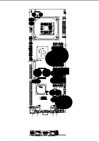
2.2 Location of Connectors and Jumpers
Component Side
JP2 |
FAN |


 ATX2
ATX2
CN6
TV1


 ATX1
ATX1
CN2
DIM1
DIM2
DIM3
DIM4
MPCI1
FP2 |
FP1 |
LPT1 |
USB3 |
USB2 |
USB1 |
|
CN3 |
|
|
COM1 |
|
|
JP1 |
Winbond -W83627HFAW |
COM2 |
|
|
IR1 |
|
IDE1 |
|
|
|
|
|
|
SATA2 |
|
|
IDE2 |
|
SATA1 |
|
|
|
|
CN8 |
CN7 |
|
FDD1 |
|
|
|
||
CN5 |
|
|
|
|
CN4 |
LAN2 |
VGA1 |
LAN1 |
USB4 |
Chapter 2 Quick Installation Guide |
2 - 3 |
F u l l-s i z e CPU Card |
F S B - 8 6 5 G |
|
|
Solder Side
CFD1
Chapter 2 Quick Installation Guide |
2 - 4 |

F u l l-s i z e CPU Card |
F S B - 8 6 5 G |
|
|
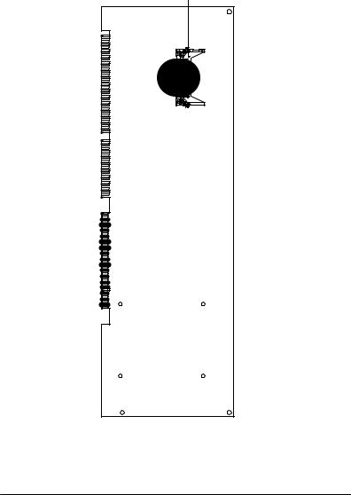
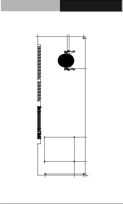
2.3 Mechanical Drawing
Component Side
41.13 51.19 |
00.0 |
60.98 |
3.02 |
|
|
0.00 |
|
|
1.47 |
|
|
79.12 |
|
10.36 |
|
|
28.79 |
28.78 |
|
56.94 |
65.74
92.13 |
|
76.40 |
94 |
90.37 |
|
|
. |
|
|
56 |
60.98 |
|
|
|
|
|
|
|
|
|
|
|
|
|
|
38.100 |
|
|
|
|
|
|
|
|
|
|
|
|
197.82 |
|
|
|
|
|
|
|
|
|
|
|
|
208.48 |
228.30 |
|
|
|
|
|
|
|
|
|
|
||
232.36 |
|
|
|
|
|
|
|
|
|
|
||
236.42 |
|
|
|
|
|
|
|
|
|
|
||
237.19 |
|
|
|
|
|
|
|
|
|
238.71 |
||
|
|
|
70.9 51.3 |
.40 |
|
|
|
|
|
|
256.24 |
|
|
|
|
|
|
82 |
268.30 |
W inbond |
W83627HF-AW |
|
|
28.94 |
273.76 |
|
|
|
|
|
276.30 |
|
|
|||||
|
|
|
|
|
|
|
|
|
|
|
|
|
|
|
|
|
286.82 |
66.38 |
|
|
|
|
|
|
38.100 |
|
|
|
|
292.29 |
|
|
|
|
|
|
||
|
|
|
|
33 |
|
|
|
|
|
|
||
|
|
318.68 |
26. |
|
|
|
|
|
|
|
|
|
|
|
|
|
|
|
|
|
|
|
|
||
318.34 |
|
329.44 |
318.62 |
|
|
|
|
|
322.85 |
|||
326.94 |
|
|
|
|
|
|
|
|
324.43 |
|||
|
|
|
|
|
|
|
|
|
330.40 |
|||
|
|
|
|
|
|
|
|
|
|
|
|
331.50 |
|
|
|
|
|
|
|
|
|
|
|
|
335.48 |
|
|
70.15 |
84.8 |
49.2 |
25.38 |
42.53 |
|
|
57.72 |
73.82 |
25.92 |
49.102 51.100 50.98 |
|
|
|
|
92.08 |
|
|
|
|
|
|
|
|
|
|
|
|
78.64 |
|
|
|
|
|
|
|
|
|
|
|
|
53.43 |
|
|
|
|
|
|
|
|
|
|
|
27.71 |
|
|
|
|
|
|
|
|
|
|
|
|
9.37 |
|
|
|
|
|
|
|
|
|
14.50 |
6.50 |
1.60 |
3.40 |
6.28 |
|
2.55 |
|
|
|
4.10 |
|
|
Chapter 2 Quick Installation Guide |
2 - 5 |
F u l l-s i z e CPU Card |
|
|
F S B - 8 6 5 G |
|
Solder Side |
|
|
|
|
51.19 |
43.56 |
CFD1 |
50.98 |
|
335.48 |
|
|
|
331.50 |
|
|
|
|
|
|
|
|
|
256.75 |
|
|
|
|
89.61 |
|
|
|
|
30.18 |
73.1 |
|
|
|
|
|
|
|
|
0.00 |
|
|
|
|
3.02 |
00.0 |
|
47.74 |
50.98 |
49.102 |
Chapter 2 Quick Installation Guide |
2 - 6 |
 Loading...