


 Loading...
Intel® Desktop Board DP45SG
Product Guide
Order Number: E30016-001

Revision History
Revision |
Revision History |
Date |
-001 |
First release of the Intel® Desktop Board DP45SG Product Guide |
June 2008 |
If an FCC declaration of conformity marking is present on the board, the following statement applies:
FCC Declaration of Conformity
This device complies with Part 15 of the FCC Rules. Operation is subject to the following two conditions:
(1) this device may not cause harmful interference, and (2) this device must accept any interference received, including interference that may cause undesired operation.
For questions related to the EMC performance of this product, contact:
Intel Corporation, 5200 N.E. Elam Young Parkway, Hillsboro, OR 97124 1-800-628-8686
This equipment has been tested and found to comply with the limits for a Class B digital device, pursuant to Part 15 of the FCC Rules. These limits are designed to provide reasonable protection against harmful interference in a residential installation. This equipment generates, uses, and can radiate radio frequency energy and, if not installed and used in accordance with the instructions, may cause harmful interference to radio communications. However, there is no guarantee that interference will not occur in a particular installation. If this equipment does cause harmful interference to radio or television reception, which can be determined by turning the equipment off and on, the user is encouraged to try to correct the interference by one or more of the following measures:
•Reorient or relocate the receiving antenna.
•Increase the separation between the equipment and the receiver.
•Connect the equipment to an outlet on a circuit other than the one to which the receiver is connected.
•Consult the dealer or an experienced radio/TV technician for help.
Any changes or modifications to the equipment not expressly approved by Intel Corporation could void the user’s authority to operate the equipment.
Tested to comply with FCC standards for home or office use.
Canadian Department of Communications Compliance Statement
This digital apparatus does not exceed the Class B limits for radio noise emissions from digital apparatus set out in the Radio Interference Regulations of the Canadian Department of Communications.
Le présent appareil numerique német pas de bruits radioélectriques dépassant les limites applicables aux appareils numériques de la classe B prescrites dans le Réglement sur le broullage radioélectrique édicté par le ministére des Communications du Canada.
Disclaimer
INFORMATION IN THIS DOCUMENT IS PROVIDED IN CONNECTION WITH INTEL® PRODUCTS. NO LICENSE, EXPRESS OR IMPLIED, BY ESTOPPEL OR OTHERWISE, TO ANY INTELLECTUAL PROPERTY RIGHTS IS GRANTED BY THIS DOCUMENT. EXCEPT AS PROVIDED IN INTEL’S TERMS AND CONDITIONS OF SALE FOR SUCH PRODUCTS, INTEL ASSUMES NO LIABILITY WHATSOEVER, AND INTEL DISCLAIMS ANY EXPRESS OR IMPLIED WARRANTY, RELATING TO SALE AND/OR USE OF INTEL PRODUCTS INCLUDING LIABILITY OR WARRANTIES RELATING TO FITNESS FOR A PARTICULAR PURPOSE, MERCHANTABILITY, OR INFRINGEMENT OF ANY PATENT, COPYRIGHT OR OTHER INTELLECTUAL PROPERTY RIGHT. Intel products are not intended for use in medical, life saving, or life sustaining applications. Intel may make changes to specifications and product descriptions at any time, without notice.
Intel Desktop Board DP45SG may contain design defects or errors known as errata which may cause the product to deviate from published specifications. Current characterized errata are available on request.
Contact your local Intel sales office or your distributor to obtain the latest specifications and before placing your product order.
Copies of documents which have an ordering number and are referenced in this document, or other Intel literature, may be obtained from Intel Corporation by going to the World Wide Web site at: http://www.intel.com/ or by calling 1-800-548-4725.
Intel and the Intel Logo are trademarks of Intel Corporation in the U. S. and other countries. * Other names and brands may be claimed as the property of others.
Copyright © 2008, Intel Corporation. All rights reserved.

Preface
This Product Guide gives information about board layout, component installation, BIOS update, and regulatory requirements for Intel® Desktop Board DP45SG.
Intended Audience
The Product Guide is intended for technically qualified personnel. It is not intended for general audiences.
Use Only for Intended Applications
All Intel Desktop Boards are evaluated as Information Technology Equipment (I.T.E.) for use in personal computers (PC) for installation in homes, offices, schools, computer rooms, and similar locations. The suitability of this product for other PC or embedded non-PC applications or other environments, such as medical, industrial, alarm systems, test equipment, etc. may not be supported without further evaluation by Intel.
Document Organization
The chapters in this Product Guide are arranged as follows:
1Desktop Board Features: a summary of product features
2Installing and Replacing Desktop Board Components: instructions on how to install the Desktop Board and other hardware components
3Updating the BIOS: instructions on how to update the BIOS
4Configuring for RAID Using Intel® Matrix Storage Technology: information about configuring your system for RAID
5Configuring for Intel® Rapid Recover Technology (Intel® RRT): information about configuring your system for Intel Rapid Recover Technology
AError Messages and Indicators: information about BIOS error messages and beep codes
BRegulatory Compliance: describes the board’s adherence to safety standards and EMC regulations and its product certifications
iii

Intel Desktop Board DP45SG Product Guide
Conventions
The following conventions are used in this manual:
 CAUTION
Cautions warn the user about how to prevent damage to hardware or loss of data.
 NOTE
NOTE
Notes call attention to important information.
Terminology
The table below gives descriptions of some common terms used in the product guide.
Term |
Description |
|
|
GB |
Gigabyte (1,073,741,824 bytes) |
|
|
GHz |
Gigahertz (one billion hertz) |
|
|
KB |
Kilobyte (1024 bytes) |
|
|
MB |
Megabyte (1,048,576 bytes) |
|
|
Mb |
Megabit (1,048,576 bits) |
|
|
MHz |
Megahertz (one million hertz) |
|
|
iv

Contents
1 |
Desktop Board Features |
|
|
Desktop Board Components................................................................................. |
11 |
|
Processor.......................................................................................................... |
13 |
|
Main Memory..................................................................................................... |
13 |
|
Intel® P45 Express Chipset .................................................................................. |
14 |
|
Audio Subsystem ............................................................................................... |
14 |
|
LAN Subsystem ................................................................................................. |
15 |
|
USB 2.0 Support ................................................................................................ |
16 |
|
Serial ATA Support............................................................................................. |
16 |
|
Serial ATA RAID ......................................................................................... |
16 |
|
Intel® Rapid Recover Technology (Intel® RRT) ................................................ |
16 |
|
Legacy I/O........................................................................................................ |
17 |
|
Expandability..................................................................................................... |
17 |
|
BIOS................................................................................................................ |
17 |
|
Serial ATA Auto Configuration....................................................................... |
17 |
|
PCI* and PCI Express* Auto Configuration ..................................................... |
17 |
|
Security Passwords..................................................................................... |
18 |
|
Hardware Management ....................................................................................... |
18 |
|
Hardware Monitoring and Fan Speed Control .................................................. |
18 |
|
Intel® Precision Cooling Technology ....................................................... |
18 |
|
Chassis Intrusion........................................................................................ |
19 |
|
Power Management ............................................................................................ |
19 |
|
Software Support ....................................................................................... |
19 |
|
ACPI.................................................................................................. |
19 |
|
Hardware Support ...................................................................................... |
19 |
|
Power Connectors ............................................................................... |
19 |
|
Fan Headers ....................................................................................... |
20 |
|
LAN Wake Capabilities.......................................................................... |
20 |
|
Instantly Available PC Technology.......................................................... |
20 |
|
+5 V Standby Power Indicator............................................................... |
21 |
|
Wake from USB .................................................................................. |
22 |
|
PME# Signal Wake-up Support.............................................................. |
22 |
|
WAKE# Signal Wake-up Support ........................................................... |
22 |
|
Wake from CIR ................................................................................... |
22 |
|
ENERGY STAR* Capable...................................................................................... |
22 |
|
Speaker............................................................................................................ |
22 |
|
Battery............................................................................................................. |
22 |
|
Real-Time Clock................................................................................................. |
23 |
2 |
Installing and Replacing Desktop Board Components |
|
|
Before You Begin ............................................................................................... |
25 |
|
Installation Precautions....................................................................................... |
26 |
|
Prevent Power Supply Overload .................................................................... |
26 |
|
Observe Safety and Regulatory Requirements................................................. |
26 |
|
Installing the I/O Shield ...................................................................................... |
27 |
|
Installing and Removing the Desktop Board ........................................................... |
28 |
v
Intel Desktop Board DP45SG Product Guide |
|
Installing and Removing a Processor..................................................................... |
29 |
Installing a Processor .................................................................................. |
29 |
Installing the Processor Fan Heat Sink ........................................................... |
33 |
Connecting the Processor Fan Heat Sink Cable................................................ |
33 |
Removing the Processor .............................................................................. |
34 |
Installing the ICH Heat Sink Decorative Cover (Optional) ......................................... |
34 |
Installing and Removing Memory.......................................................................... |
35 |
Guidelines for Dual Channel Memory Configuration.......................................... |
35 |
Two or Four DIMMs ............................................................................. |
35 |
Three DIMMs ...................................................................................... |
36 |
Installing DIMMs ........................................................................................ |
37 |
Removing DIMMs........................................................................................ |
39 |
Installing and Removing a PCI Express x16 Card .................................................... |
40 |
Installing Multiple PCI Express x16 Graphics Cards .......................................... |
40 |
Installing a PCI Express x16 Card ................................................................. |
41 |
Removing a PCI Express x16 Card ................................................................ |
42 |
Connecting the Serial ATA (SATA) Cables .............................................................. |
43 |
Connecting to the Internal Headers and Connectors ................................................ |
44 |
S/PDIF Connector ....................................................................................... |
45 |
Front Panel Audio Header ............................................................................ |
45 |
IEEE 1394a Header..................................................................................... |
46 |
Consumer IR (CIR) Headers ......................................................................... |
46 |
Chassis Intrusion Header ............................................................................. |
47 |
Front Panel Header ..................................................................................... |
47 |
Alternate Front Panel Power LED Header ........................................................ |
48 |
HD Audio Link Header ................................................................................. |
48 |
USB 2.0 Headers ........................................................................................ |
49 |
Serial Port Header ...................................................................................... |
49 |
Connecting to the Flexible Audio System ............................................................... |
50 |
Connecting Chassis Fan and Power Supply Cables................................................... |
51 |
Connecting Chassis Fan Cables ..................................................................... |
51 |
Connecting Power Supply Cables .................................................................. |
52 |
Setting the BIOS Configuration Jumper ................................................................. |
53 |
Clearing Passwords ............................................................................................ |
54 |
Replacing the Battery ......................................................................................... |
55 |
3 Updating the BIOS |
|
Updating the BIOS with the Intel® Express BIOS Update Utility................................. |
61 |
Updating the BIOS with the ISO Image BIOS Update File or the Iflash Memory |
|
Update Utility............................................................................................... |
62 |
Obtaining the BIOS Update File .................................................................... |
62 |
Updating the BIOS with the ISO Image BIOS Update File ................................. |
62 |
Updating the BIOS with the Iflash Memory Update Utility ................................. |
63 |
Recovering the BIOS................................................................................... |
64 |
vi
Contents
4 |
Configuring for RAID Using Intel® Matrix Storage Technology |
|
|
(Intel® MST) |
|
|
Configuring the BIOS.......................................................................................... |
65 |
|
Creating Your RAID Set....................................................................................... |
65 |
|
Loading the Intel Matrix Storage Technology RAID Drivers and Software for |
|
|
Microsoft Windows* XP.................................................................................. |
66 |
|
Setting Up a “RAID Ready” System....................................................................... |
66 |
5 |
Configuring for Intel® Rapid Recover Technology (Intel® RRT) |
|
|
Enabling Intel Rapid Recover Technology............................................................... |
67 |
|
Creating a Recovery Volume................................................................................ |
68 |
|
Creating a Recovery Volume Using the RAID Option ROM ................................. |
68 |
|
Creating a Recovery Volume Using the Intel® Matrix Storage Console ................ |
68 |
|
Disk Synchronization Mode.................................................................................. |
69 |
|
Mounting the Recovery Disk ................................................................................ |
69 |
A |
Error Messages and Indicators |
|
|
BIOS Beep Codes............................................................................................... |
71 |
|
BIOS Error Messages .......................................................................................... |
71 |
B |
Regulatory Compliance |
|
|
Safety Standards ............................................................................................... |
73 |
|
Place Battery Marking ................................................................................. |
73 |
|
European Union Declaration of Conformity Statement.............................................. |
74 |
|
Product Ecology Statements ................................................................................ |
75 |
|
Recycling Considerations ............................................................................. |
75 |
|
Lead-free 2LI/Pb-free 2LI Board ................................................................... |
78 |
|
Restriction of Hazardous Substances (RoHS) .................................................. |
79 |
|
EU RoHS ............................................................................................ |
79 |
|
China RoHS ........................................................................................ |
80 |
|
EMC Regulations ................................................................................................ |
82 |
|
Ensure Electromagnetic Compatibility (EMC) Compliance.................................. |
83 |
|
Product Certifications.......................................................................................... |
84 |
|
Board-Level Certification Markings ................................................................ |
84 |
|
Chassis and Component Certifications............................................................ |
85 |
Figures |
|
|
|
1. Intel Desktop Board DP45SG Components........................................................ |
11 |
|
2. LAN Connector LEDs ..................................................................................... |
15 |
|
3. Location of the Standby Power Indicator .......................................................... |
21 |
|
4. Installing the I/O Shield ................................................................................ |
27 |
|
5. Intel Desktop Board DP45SG Mounting Screw Hole Locations .............................. |
28 |
|
6. Lift the Socket Lever ..................................................................................... |
29 |
|
7. Lift the Load Plate......................................................................................... |
30 |
|
8. Remove the Protective Socket Cover ............................................................... |
30 |
|
9. Remove the Processor from the Protective Processor Cover ................................ |
31 |
|
10. Install the Processor ..................................................................................... |
31 |
|
11. Close the Load Plate ..................................................................................... |
32 |
|
12. Connecting the Processor Fan Heat Sink Cable.................................................. |
33 |
|
13. Installing the ICH Heat Sink Decorative Cover .................................................. |
34 |
vii
Intel Desktop Board DP45SG Product Guide |
|
|
14. |
Dual Channel Memory Configuration with Two DIMMs ........................................ |
35 |
15. |
Dual Channel Memory Configuration with Four DIMMs........................................ |
36 |
16. |
Dual Channel Memory Configuration with Three DIMMs ...................................... |
36 |
17. |
Use DDR3 DIMMs ......................................................................................... |
37 |
18. |
Installing a DIMM ......................................................................................... |
38 |
19. |
Installing Two PCI Express x16 Graphics Cards ................................................. |
40 |
20. |
Installing a PCI Express x16 Card ................................................................... |
41 |
21. |
Removing a PCI Express x16 Card .................................................................. |
42 |
22. |
Connecting a Serial ATA Cable........................................................................ |
43 |
23. |
Internal Headers and Connectors .................................................................... |
44 |
24. |
Back Panel Audio Connectors ......................................................................... |
50 |
25. |
Location of the Chassis Fan Headers................................................................ |
51 |
26. |
Connecting Power Supply Cables .................................................................... |
52 |
27. |
Location of the BIOS Configuration Jumper Block .............................................. |
53 |
28. |
Removing the Battery ................................................................................... |
60 |
29. |
Intel Desktop Board DP45SG China RoHS Material Self Declaration Table.............. |
81 |
Tables |
|
|
1. |
Feature Summary.......................................................................................... |
9 |
2. |
Intel Desktop Board DP45SG Components........................................................ |
12 |
3. |
LAN Connector LEDs ..................................................................................... |
15 |
4. |
S/PDIF Connector Signal Names ..................................................................... |
45 |
5. |
Front Panel Audio Header Signal Names for HD Audio ........................................ |
45 |
6. |
Front Panel Audio Header Signal Names for AC ’97 Audio ................................... |
45 |
7. |
IEEE 1394a Header Signal Names ................................................................... |
46 |
8. |
Front Panel CIR Receiver (Input) Header Signal Names ...................................... |
46 |
9. |
Back Panel CIR Header Emitter (Output) Header Signal Names ........................... |
47 |
10. |
Chassis Intrusion Header Signal Names ........................................................... |
47 |
11. |
Front Panel Header Signal Names ................................................................... |
47 |
12. |
Alternate Front Panel Power LED Header Signal Names ...................................... |
48 |
13. |
HD Audio Link Header Signal Names ............................................................... |
48 |
14. |
USB 2.0 Header Signal Names........................................................................ |
49 |
15. |
Serial Port Header Signal Names..................................................................... |
49 |
16. |
Jumper Settings for the BIOS Setup Program Modes.......................................... |
54 |
17. |
Beep Codes ................................................................................................. |
71 |
18. |
BIOS Error Messages .................................................................................... |
71 |
19. |
Safety Standards.......................................................................................... |
73 |
20. |
Lead-Free Second Level Interconnect Marks ..................................................... |
79 |
21. |
China RoHS Environmentally Friendly Use Period Mark ....................................... |
80 |
22. |
EMC Regulations........................................................................................... |
82 |
23. |
Product Certification Markings ........................................................................ |
84 |
viii

1 Desktop Board Features
This chapter briefly describes the features of Intel® Desktop Board DP45SG. Table 1 summarizes the major features of the Desktop Board.
Table 1. Feature Summary
Form Factor |
ATX (294.64 millimeters [11.60 inches] x 243.84 millimeters |
||
|
[9.60 inches]) |
||
|
|
|
|
Processor |
Support for an Intel® processor in the LGA775 package |
||
Main Memory |
• |
Four 240-pin, DDR3 1.5 V SDRAM Dual Inline Memory Module |
|
|
|
(DIMM) sockets |
|
|
• |
1333/1066/800 MHz DDR3 SDRAM interface |
|
|
• |
Support for up to 8 GB of system memory |
|
|
|
|
|
Chipset |
Intel® P45 Express Chipset consisting of: |
||
|
• |
Intel P45 Express Chipset Memory Controller Hub (MCH) with Direct |
|
|
|
Media Interface interconnect |
|
|
• |
Intel® 82801JR I/O Controller Hub (ICH10R) supporting Intel® |
|
|
|
Matrix Storage Technology (Intel® MST) |
|
Graphics |
Support for multiple PCI Express* graphics cards |
||
|
|
|
|
Audio |
• |
Independent multi-streaming 8-channel (7.1) audio and 2-channel |
|
|
|
audio subsystem, featuring: |
|
|
|
― Intel® High Definition Audio (Intel® HD Audio) interface |
|
|
|
― IDT* 92HD73E audio codec |
|
|
• |
HD Audio Link header |
|
|
• |
Front panel header |
|
|
• |
Two independent S/PDIF connectors |
|
|
|
― Onboard 3-pin connector |
|
|
|
― Back panel optical connector |
|
|
|
|
|
Expansion |
• |
Two PCI Express 2.0 x16 ports |
|
Capabilities |
• |
Two PCI Express 1.1 x1 ports |
|
|
• |
Three PCI* bus connectors |
|
|
|
|
|
Legacy I/O Support |
Legacy I/O Controller that provides: |
||
|
• |
Consumer Infrared (CIR) support |
|
|
• |
Serial port via an onboard header |
|
|
|
|
|
Peripheral |
• |
Up to 12 USB 2.0 ports: |
|
Interfaces |
|
― Six ports routed to the back panel |
|
|
|
― Six ports routed to two USB headers |
|
|
• |
Up to two IEEE 1394a ports: |
|
|
|
― One port routed to the back panel |
|
|
|
― One port routed to an IEEE 1394a header |
|
|
• |
Six Serial ATA (SATA) channels (3.0 Gb/s) via ICH10R, including |
|
|
|
one back panel eSATA channel |
|
|
|
|
|
|
|
continued |
|
9

Intel Desktop Board DP45SG Product Guide
Table 1. Feature Summary (continued)
RAID Support |
Intel Matrix Storage Technology for Serial ATA including support for |
||
|
Intel® Rapid Recover Technology (Intel® RRT) |
||
LAN Support |
Gigabit LAN subsystem, including: |
||
|
• |
Intel® 82567LF Gigabit (10/100/1000 Mb/s) Ethernet LAN controller |
|
|
• |
RJ-45 back panel connector with integrated status LEDs |
|
BIOS |
• |
Intel® Platform Innovation Framework for EFI |
|
|
• |
32 Mb symmetrical flash memory device |
|
|
• |
Support for SMBIOS |
|
|
• |
Intel® Rapid BIOS Boot |
|
|
• |
Intel® Express BIOS Update |
|
Power Management |
• |
Support for Advanced Configuration and Power Interface (ACPI) |
|
|
• |
Suspend to RAM (STR) |
|
|
• |
Wake on USB, PCI, PCI Express, LAN, CIR, and front panel |
|
|
• |
ENERGY STAR* capable |
|
|
|
|
|
Hardware |
Hardware monitor with: |
||
Management |
• |
Four fan sensing inputs used to monitor fan activity |
|
|
• |
Intel® Precision Cooling Technology fan speed control |
|
|
• |
Voltage sensing to detect out of range values |
|
|
|
|
|
Supported |
• |
Microsoft Windows Vista* Ultimate |
|
Operating Systems |
• |
Microsoft Windows Vista Enterprise |
|
|
• |
Microsoft Windows Vista Business |
|
|
• |
Microsoft Windows Vista Home Premium |
|
|
• |
Microsoft Windows Vista Home Basic |
|
|
• |
Microsoft Windows Vista Ultimate 64-bit edition |
|
|
• |
Microsoft Windows Vista Enterprise 64-bit edition |
|
|
• |
Microsoft Windows Vista Business 64-bit edition |
|
|
• |
Microsoft Windows Vista Home Premium 64-bit edition |
|
|
• |
Microsoft Windows Vista Home Basic 64-bit edition |
|
|
• |
Microsoft Windows* XP Media Center Edition 2005 |
|
|
• |
Microsoft Windows XP Professional |
|
|
• |
Microsoft Windows XP Professional x64 Edition |
|
|
• |
Microsoft Windows XP Home |
|
|
|
|
|
For more information about Intel Desktop Board DP45SG, including the Technical Product Specification (TPS), BIOS updates, and device drivers, go to http://support.intel.com/support/motherboards/desktop/.
10

Desktop Board Features
Desktop Board Components
Figure 1 shows the approximate location of the major components on Intel Desktop Board DP45SG.
Figure 1. Intel Desktop Board DP45SG Components
11
Intel Desktop Board DP45SG Product Guide
Table 2. Intel Desktop Board DP45SG Components
Label |
Description |
|
|
A |
PCI bus connector 3 |
|
|
B |
S/PDIF connector |
|
|
C |
PCI bus connector 2 |
|
|
D |
PCI bus connector 1 |
|
|
E |
PCI Express 2.0 x16 secondary connector |
|
|
F |
PCI Express 1.1 x1 connector 2 |
|
|
G |
IEEE 1394a header |
|
|
H |
PCI Express 1.1 x1 connector |
|
|
I |
PCI Express 2.0 x16 primary connector |
|
|
J |
Auxiliary PCI Express graphics power connector (1 x 4 pin) |
|
|
K |
Back panel connectors |
|
|
L |
Processor fan header (4-pin) |
|
|
M |
Rear chassis fan header (3-pin) |
|
|
N |
12 V processor core voltage connector (2 x 2 pin) |
|
|
O |
Processor socket |
|
|
P |
DDR3 DIMM 0 sockets |
|
|
Q |
DDR3 DIMM 1 sockets |
|
|
R |
Main power connector (2 x 12 pin) |
|
|
S |
Front chassis fan header (3-pin) |
|
|
T |
Chassis intrusion header |
|
|
U |
BIOS configuration jumper block |
|
|
V |
Alternate front panel power LED header |
|
|
W |
Front panel header |
|
|
X |
Front panel CIR receiver (input) header |
|
|
Y |
Serial ATA connectors (5) |
|
|
Z |
Speaker |
|
|
AA |
Auxiliary chassis fan header (4-pin) |
|
|
BB |
USB 2.0 headers (3) |
|
|
CC |
High Definition Audio Link header |
|
|
DD |
Battery |
|
|
EE |
Serial header |
|
|
FF |
Back panel CIR transmitter (output) header |
|
|
GG |
Front panel audio header |
|
|
12

Desktop Board Features
Processor
 CAUTION
Failure to use an appropriate power supply and/or not connecting the 12 V (2 x 2 pin) power connector to the Desktop Board may result in damage to the board, or the system may not function properly.
Intel Desktop Board DP45SG supports an Intel processor in the LGA775 package. Processors are not included with the Desktop Board and must be purchased separately. The processor connects to the Desktop Board through the LGA775 socket.
Go to the following locations for more information about:
•Instructions on installing or upgrading the processor, page 29 in Chapter 2
•Supported processors for Intel Desktop Board DP45SG, http://processormatch.intel.com
Main Memory
 NOTE
NOTE
To be fully compliant with all applicable Intel® SDRAM memory specifications, the board should be populated with DIMMs that support the Serial Presence Detect (SPD) data structure. If your memory modules do not support SPD, you will see a notification to this effect on the screen at power up. The BIOS will attempt to configure the memory controller for normal operation.
The Desktop Board supports the dual or single channel memory configurations defined below:
•Four 240-pin Double Data Rate 3 (DDR3) SDRAM Dual Inline Memory Module (DIMM) connectors with gold-plated contacts.
•1333/1066/800 MHz DDR3 SDRAM interface
•Unbuffered, non-registered singleor double-sided DIMMs
•Non-ECC DDR3 memory
•Serial Presence Detect (SPD) memory only
•Up to 4 GB utilizing 512 Mb or 1 Gb technology
•Up to 8 GB utilizing 1 Gb or 2 Gb technology
 NOTE
NOTE
System resources and hardware (such as PCI and PCI Express) require physical memory address locations that can reduce available addressable system memory. This could result in a reduction of as much as 1 GB or more of physical addressable memory being available to the operating system and applications, depending on the system configuration and operating system.
13
Intel Desktop Board DP45SG Product Guide
Go to the following locations for more information about:
•SDRAM specifications, http://www.intel.com/technology/memory/
•Installing memory, page 35 in Chapter 2
•Tested memory, http://www.cmtlabs.com/mbsearch.asp
Intel® P45 Express Chipset
The Intel P45 Express Chipset consists of the following devices:
•Intel P45 Express Chipset Memory Controller Hub (MCH) with Direct Media Interface (DMI) interconnect
•Intel 82801JR I/O Controller Hub (ICH10R) with DMI interconnect
The MCH provides interfaces to the processor, memory, PCI Express bus, and the DMI interconnect. ICH10R is a centralized controller for the board’s I/O paths.
For more information about the Intel P45 Express Chipset, go to http://developer.intel.com/products/chipsets/index.htm.
Audio Subsystem
The onboard audio subsystem consists of the following components:
•Intel® ICH10R I/O controller hub
•IDT 92HD73E audio codec
The subsystem has the following headers and connectors:
•Back panel audio connectors, including an S/PDIF optical port
•Front panel header that provides mic in and line out signals for front panel audio connectors. High definition (HD) Audio or AC’97 Audio front panels can be supported.
•HD Audio Link header used with HDMI video cards
•Onboard S/PDIF connector that can be used for HDMI video cards that do not work with the HD Audio Link header
The audio subsystem supports the following features:
•Dolby* Home Theater
•A signal-to-noise (S/N) ratio of 95 dB
•Independent multi-streaming 8-channel (7.1) audio (using the back panel audio connectors) and 2-channel audio (using the Intel High Definition Audio front panel header)
Go to the following locations for more information about:
•Audio drivers and utilities http://support.intel.com/support/motherboards/desktop/
•The location of the onboard audio headers, Figure 23 on page 44
•The signal names for the front panel header and the HD Audio Link header, page 48
•The back panel audio connectors, Figure 24 on page 50
14
Desktop Board Features
LAN Subsystem
The LAN subsystem includes:
•Intel ICH10R
•Intel 82567LF Gigabit (10/100/1000 Mb/s) Ethernet LAN controller
•RJ-45 LAN connector with integrated status LEDs
The subsystem features:
•CSMA/CD protocol engine
•LAN connect interface between ICH10R and the LAN controller
•PCI Express power management
For information about LAN software and drivers go to
http://support.intel.com/support/motherboards/desktop
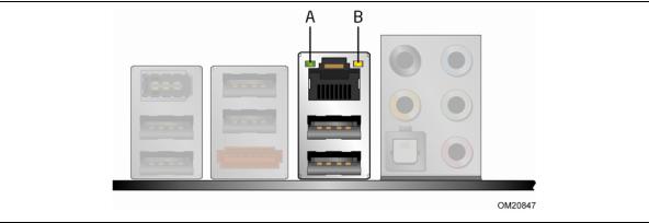
Two LEDs are built into the RJ-45 LAN connector located on the back panel (see Figure 2). These LEDs indicate the status of the LAN.
Figure 2. LAN Connector LEDs
Table 3 describes the LED states when the board is powered up and the LAN subsystem is operating.
Table 3. LAN Connector LEDs
LED |
LED Color |
LED State |
Indicates |
|
|
|
|
A |
Green |
Off |
LAN link is not established |
|
|
|
|
|
|
On |
LAN link is established |
|
|
|
|
|
|
Blinking |
LAN activity is occurring |
|
|
|
|
B |
N/A |
Off |
10 Mb/s data rate |
|
|
|
|
|
Green |
On |
100 Mb/s data rate |
|
|
|
|
|
Yellow |
On |
1000 Mb/s data rate |
|
|
|
|
15
Intel Desktop Board DP45SG Product Guide
USB 2.0 Support
The Desktop Board supports up to 12 USB 2.0 ports (six ports routed to back panel connectors and six ports routed to three onboard headers) via the ICH10R. USB 2.0 ports are backward compatible with USB 1.1 devices. USB 1.1 devices will function normally at USB 1.1 speeds.
USB 2.0 support requires both an operating system and drivers that fully support USB 2.0 transfer rates. Disabling Hi-Speed USB in the BIOS reverts all USB 2.0 ports to USB 1.1 operation. This may be required to accommodate operating systems that do not support USB 2.0.
Serial ATA Support
Intel Desktop Board DP45SG supports five onboard Serial ATA channels and one eSATA channel (3.0 Gb/s) via ICH10R.
Serial ATA RAID
The five onboard Serial ATA channels support the following RAID (Redundant Array of Independent Drives) levels via Intel Matrix Storage Technology:
•RAID 0 - data striping
•RAID 1 - data mirroring
•RAID 0+1 (or RAID 10) - data striping and data mirroring
•RAID 5 - distributed parity
For information on configuring your system for RAID using Intel Matrix Storage Technology go to Chapter 4.
Intel® Rapid Recover Technology (Intel® RRT)
The Desktop Board supports Intel Rapid Recover Technology which enables fast and easy recovery of your data in the event of a hard drive failure. It allows you to maintain a complete copy of your primary or master drive onto a second hard drive, the recovery drive. If the master hard drive should fail, either from a mechanical failure or the result of a virus, recovery is as simple as booting from the recovery drive. The recovery drive can be attached to your system via any standard SATA or eSATA connection.
Intel Rapid Recover Technology also provides the added benefit of allowing the recovery drive to be mounted as a read-only volume so you can quickly copy files from the recovery drive when individual files need to be recovered.
For information on configuring your system for Intel Rapid Recover Technology see Chapter 5.
16
Desktop Board Features
Legacy I/O
Intel Desktop Board DP45SG includes an I/O controller that provides the following legacy I/O features:
•One serial port via an onboard header
•Consumer Infrared (CIR) support
•Low pin count (LPC) interface
•Intelligent power management, including a programmable wake up event interface
•PCI power management support
Expandability
Intel Desktop Board DP45SG provides the following expansion capability:
•Two PCI Express 2.0 x16 connectors (compatible with PCI Express 1.1 add-in cards)
•Two PCI Express 1.1 x1 connectors
•Three PCI bus connectors
BIOS
The BIOS provides the Power-On Self-Test (POST), the BIOS Setup program, and the PCI/PCI Express auto-configuration utilities. The BIOS is stored in the Serial Peripheral Interface (SPI) Flash device.
The BIOS can be updated by following the instructions on page 61 in Chapter 3.
Serial ATA Auto Configuration
If you install a Serial ATA device (such as a hard drive) in your computer, the autoconfiguration utility in the BIOS automatically detects and configures the device for your computer. You do not need to run the BIOS Setup program after installing a Serial ATA device. You can override the auto-configuration options by specifying manual configuration in the BIOS Setup program.
PCI* and PCI Express* Auto Configuration
If you install a PCI/PCI Express add-in card in your computer, the PCI/PCI Express auto-configuration utility in the BIOS automatically detects and configures the resources (IRQs, DMA channels, and I/O space) for that add-in card. You do not need to run the BIOS Setup program after you install a PCI/PCI Express add-in card.
17
Intel Desktop Board DP45SG Product Guide
Security Passwords
The BIOS includes security features that restrict whether the BIOS Setup program can be accessed and who can boot the computer. A supervisor password and a user password can be set for the BIOS Setup and for booting the computer, with the following restrictions:
•The supervisor password gives unrestricted access to view and change all Setup options. If only the supervisor password is set, pressing <Enter> at the password prompt of Setup gives the user restricted access to Setup.
•If both the supervisor and user passwords are set, you must enter either the supervisor password or the user password to access Setup. Setup options are then available for viewing and changing depending on whether the supervisor or user password was entered.
•Setting a user password restricts who can boot the computer. The password prompt is displayed before the computer is booted. If only the supervisor password is set, the computer boots without asking for a password. If both passwords are set, you can enter either password to boot the computer.
Related Links:
For instructions on resetting the password, go to Clearing Passwords on page 54.
Hardware Management
The hardware management features of Intel Desktop Board DP45SG enable the board to be compatible with the Wired for Management (WfM) specification. The board has several hardware management features including the following:
•Fan speed monitoring and control
•Thermal and voltage monitoring
•Chassis intrusion detection
Hardware Monitoring and Fan Speed Control
The features of the hardware monitoring and fan speed control include:
•Monitoring of power supply voltages to detect levels above and below acceptable values
•Intel Precision Cooling Technology fan speed control, delivering acousticallyoptimized thermal management
•A thermal sensor in the processor and a remote thermal sensor on the board
•Thermally monitored closed-loop fan control, for all onboard fans, that can adjust fan speed or switch the fans off as needed
Intel® Precision Cooling Technology
Intel Precision Cooling Technology automatically adjusts processor fan speed based on the processor temperature and adjusts chassis fan speeds based on the internal system temperature.
18
Desktop Board Features
Chassis Intrusion
The board supports a chassis security feature that detects if the chassis cover has been removed. The security feature uses a mechanical switch on the chassis that can be connected to the chassis intrusion header on the Desktop Board. See Figure 23 for the location of the chassis intrusion header.
Power Management
Power management is implemented at several levels, including software support through the Advanced Configuration and Power Interface (ACPI) and the following hardware support:
•Power connectors
•Fan headers
•LAN wake capabilities
•Instantly Available PC technology (Suspend to RAM)
•+5 V standby power indicator LED
•Wake from USB
•PCI Power Management Event signal (PME#) wakeup support
•PCI Express WAKE# signal wakeup support
•Wake from Consumer IR
Software Support
ACPI
ACPI gives the operating system direct control over the power management and Plug and Play functions of a computer. The use of ACPI with the Desktop Board requires an operating system that provides full ACPI support.
Hardware Support
Power Connectors
ATX12V-compliant power supplies can turn off the computer power through system control. When an ACPI-enabled computer receives the correct command, the power supply removes all non-standby voltages.
When resuming from an AC power failure, the computer returns to the power state it was in before power was interrupted (either on or off). The computer’s response can be set by using the Last Power State feature in the BIOS Setup program’s Boot menu.
The Desktop Board has three power connectors. See Figure 26 on page 52 for the location of the power connectors.
19
Intel Desktop Board DP45SG Product Guide
Fan Headers
The function/operation of the fans is as follows:
•The fans are on when the computer is in the ACPI S0 state.
•The fans are off when the computer is in the ACPI S3, S4, or S5 state.
•Each fan header is wired to a tachometer input of the hardware monitoring and control device.
•All fan headers support closed-loop fan control that can adjust the fan speed or switch the fan on or off as needed.
•All fan headers have a +12 V DC connection.
The Desktop Board has a 4-pin processor fan header, one 4-pin and two 3-pin chassis fan headers.
LAN Wake Capabilities
 CAUTION
For LAN wake capabilities, the 5 V standby line for the power supply must be capable of delivering adequate +5 V standby current. Failure to provide adequate standby current when using this feature can damage the power supply.
LAN wakeup capabilities enable remote wake-up of the computer through a network. The LAN subsystem monitors network traffic and upon detecting a Magic Packet* frame, it asserts a wake-up signal that powers up the computer.
Instantly Available PC Technology
 CAUTIONS
For Instantly Available PC technology, the 5 V standby line for the power supply must be capable of delivering adequate +5 V standby current. Failure to provide adequate standby current when using this feature can damage the power supply and/or effect ACPI S3 sleep state functionality.
Power supplies used with this Desktop Board must be able to provide enough standby current to support the standard Instantly Available (ACPI S3 sleep state) configuration. If the standby current necessary to support multiple wake events from the PCI and/or USB buses exceeds power supply capacity, the Desktop Board may lose register settings stored in memory.
Instantly Available PC technology enables the board to enter the ACPI S3 (Suspend-to- RAM) sleep state. While in the S3 sleep state, the computer will appear to be off. If the computer has a dual-colored power LED on the front panel, the sleep state is indicated by the LED turning amber. When signaled by a wake-up device or event, the computer quickly returns to its last known awake state.
20
Desktop Board Features
The Desktop Board supports the PCI Bus Power Management Interface Specification. Add-in cards that support this specification can participate in power management and can be used to wake the computer.
+5 V Standby Power Indicator
 CAUTION
If the AC power has been switched off and the standby power indicator is still lit, disconnect the power cord before installing or removing any devices connected to the board. Failure to do so could damage the board and any attached devices.
The Desktop Board’s standby power indicator, shown in Figure 3, is lit when there is standby power still present on the board even when the computer appears to be off. For example, when this LED is lit, standby power is still present at the memory module sockets and the PCI/PCI Express connectors.
Figure 3. Location of the Standby Power Indicator
For more information on standby current requirements for the Desktop Board, refer to the Technical Product Specification by going to the following link, finding the product, and selecting Product Documentation from the left-hand menu: http://support.intel.com/support/motherboards/desktop/
21

Intel Desktop Board DP45SG Product Guide
Wake from USB
 NOTE
NOTE
Wake from USB requires the use of a USB peripheral that supports Wake from USB and an operating system that supports Wake from USB.
USB bus activity wakes the computer from an ACPI S3 state.
PME# Signal Wake-up Support
When the PME# signal on the PCI bus is asserted, the computer wakes from an ACPI S1, S3, S4, or S5 state.
WAKE# Signal Wake-up Support
When the WAKE# signal on the PCI Express bus is asserted, the computer wakes from an ACPI S1, S3, S4, or S5 state.
Wake from CIR
Consumer IR device activity wakes the computer from an ACPI S1 or S3 state.
ENERGY STAR* Capable
In 2007, the US Department of Energy and the US Environmental Protection Agency revised the ENERGY STAR requirements. Intel worked directly with these two governmental agencies to define the new requirements. This Desktop Board meets the ENERGY STAR Category C.
For information and recommendations concerning the new ENERGY STAR requirements, go to the following location http://intel.com/go/energystar.
Speaker
A speaker is mounted on the Desktop Board. The speaker provides audible error code (beep code) information during the Power-On Self-Test (POST). Refer to Appendix A for a description of the board’s beep codes.
Battery
A battery on the Desktop Board keeps the values in CMOS RAM and the clock current when the computer is turned off. Go to page 55 for instructions on how to replace the battery.
22
Desktop Board Features
Real-Time Clock
The Desktop Board has a time-of-day clock and 100-year calendar. The battery on the Desktop Board keeps the clock current when the computer is turned off.
23
Intel Desktop Board DP45SG Product Guide
24

2Installing and Replacing Desktop Board Components
This chapter tells you how to:
•Install the I/O shield
•Install and remove the Desktop Board
•Install and remove a processor
•Install the ICH heat sink decorative cover (optional)
•Install and remove memory
•Install and remove PCI Express x16 cards
•Connect the Serial ATA cables
•Connect to the internal headers and connectors
•Connect to the audio system
•Connect chassis fan and power supply cables
•Set the BIOS configuration jumper
•Clear passwords
•Replace the battery
Before You Begin
 CAUTIONS
The procedures in this chapter assume familiarity with the general terminology associated with personal computers and with the safety practices and regulatory compliance required for using and modifying electronic equipment.
Disconnect the computer from its power source and from any telecommunications links, networks, or modems before performing any of the procedures described in this chapter. Failure to disconnect power, telecommunications links, networks, or modems before you open the computer or perform any procedures can result in personal injury or equipment damage. Some circuitry on the board can continue to operate even though the front panel power button is off.
Follow these guidelines before you begin:
•Always follow the steps in each procedure in the correct order.
•Set up a log to record information about your computer, such as model, serial numbers, installed options, and configuration information.
•Electrostatic discharge (ESD) can damage components. Perform the procedures described in this chapter only at an ESD workstation using an antistatic wrist strap and a conductive foam pad. If such a station is not available, you can provide some ESD protection by wearing an antistatic wrist strap and attaching it to a metal part of the computer chassis.
25
Intel Desktop Board DP45SG Product Guide
Installation Precautions
When you install and test the Intel Desktop Board, observe all warnings and cautions in the installation instructions.
To avoid injury, be careful of:
•Sharp pins on connectors
•Sharp pins on printed circuit assemblies
•Rough edges and sharp corners on the chassis
•Hot components (such as processors, voltage regulators, and heat sinks)
•Damage to wires that could cause a short circuit
Observe all warnings and cautions that instruct you to refer computer servicing to qualified technical personnel.
Prevent Power Supply Overload
Do not overload the power supply output. To avoid overloading the power supply, make sure that the calculated total current loads of all the modules within the computer is less than the output current rating of each of the power supplies output circuits.
Observe Safety and Regulatory Requirements
Read and follow the instructions in this section and the instructions supplied with the chassis and associated modules. If you do not follow these instructions and the instructions provided by the chassis and module suppliers, you increase your safety risk and the possibility of noncompliance with regional laws and regulations. If the instructions for the chassis are inconsistent with these instructions or the instructions for associated modules, contact the supplier to find out how you can ensure that your computer meets safety and regulatory requirements.
For information about the Desktop Board’s regulatory compliance, go to Appendix B.
26
Loading...