


 Loading...
Intel® Desktop Board
D925XCV/D925XBC
Technical Product Specification
June 2004
Order Number: C68597-001
The Intel® Desktop Board D925XCV/D925XBC may contain design defects or errors known as errata that may cause the product to deviate from published specifications. Current characterized errata are documented in the Intel Desktop Board D925XCV/D925XBC Specification Update.

Revision History
Revision |
Revision History |
Date |
|
|
|
-001 |
First release of the Intel® Desktop Board D925XCV/D925XBC Technical |
June 2004 |
|
Product Specification |
|
|
|
|
This product specification applies to only standard Intel® Desktop Boards D925XCV and D925XBC with BIOS identifier CV92510A.86A.
Changes to this specification will be published in the Intel Desktop Board D925XCV/D925XBC Specification Update before being incorporated into a revision of this document.
INFORMATION IN THIS DOCUMENT IS PROVIDED IN CONNECTION WITH INTEL® PRODUCTS. NO LICENSE, EXPRESS OR IMPLIED, BY ESTOPPEL OR OTHERWISE, TO ANY INTELLECTUAL PROPERTY RIGHTS IS GRANTED BY THIS DOCUMENT. EXCEPT AS PROVIDED IN INTEL’S TERMS AND CONDITIONS OF SALE FOR SUCH PRODUCTS, INTEL ASSUMES NO LIABILITY WHATSOEVER, AND INTEL DISCLAIMS ANY EXPRESS OR IMPLIED WARRANTY, RELATING TO SALE AND/OR USE OF INTEL® PRODUCTS INCLUDING LIABILITY OR WARRANTIES RELATING TO FITNESS FOR A PARTICULAR PURPOSE, MERCHANTABILITY, OR INFRINGEMENT OF ANY PATENT, COPYRIGHT OR OTHER INTELLECTUAL PROPERTY RIGHT. INTEL PRODUCTS ARE NOT INTENDED FOR USE IN MEDICAL, LIFE SAVING, OR LIFE SUSTAINING APPLICATIONS.
Intel Corporation may have patents or pending patent applications, trademarks, copyrights, or other intellectual property rights that relate to the presented subject matter. The furnishing of documents and other materials and information does not provide any license, express or implied, by estoppel or otherwise, to any such patents, trademarks, copyrights, or other intellectual property rights.
Intel may make changes to specifications and product descriptions at any time, without notice.
Designers must not rely on the absence or characteristics of any features or instructions marked “reserved” or “undefined.” Intel reserves these for future definition and shall have no responsibility whatsoever for conflicts or incompatibilities arising from future changes to them.
Intel® desktop boards may contain design defects or errors known as errata, which may cause the product to deviate from published specifications. Current characterized errata are available on request.
Contact your local Intel sales office or your distributor to obtain the latest specifications before placing your product order.
Copies of documents which have an ordering number and are referenced in this document, or other Intel literature, may be obtained from:
Intel Corporation
P.O. Box 5937
Denver, CO 80217-9808
or call in North America 1-800-548-4725, Europe 44-0-1793-431-155, France 44-0-1793-421-777, Germany 44-0-1793-421-333, other Countries 708-296-9333.
Intel, Pentium, and Celeron are registered trademarks of Intel Corporation or its subsidiaries in the United States and other countries.
* Other names and brands may be claimed as the property of others.

Preface
This Technical Product Specification (TPS) specifies the board layout, components, connectors, power and environmental requirements, and the BIOS for these Intel® Desktop Boards: D925XCV and D925XBC. It describes the standard product and available manufacturing options.
Intended Audience
The TPS is intended to provide detailed, technical information about the Desktop Boards D925XCV and D925XBC and their components to the vendors, system integrators, and other engineers and technicians who need this level of information. It is specifically not intended for general audiences.
What This Document Contains
Chapter Description
1A description of the hardware used on the Desktop Boards D925XCV and D925XBC
2A map of the resources of the Desktop Boards
3The features supported by the BIOS Setup program
4A description of the BIOS error messages, beep codes, and POST codes
Typographical Conventions
This section contains information about the conventions used in this specification. Not all of these symbols and abbreviations appear in all specifications of this type.
Notes, Cautions, and Warnings
NOTE
Notes call attention to important information.
INTEGRATOR’S NOTES
Integrator’s notes are used to call attention to information that may be useful to system integrators.
CAUTION
Cautions are included to help you avoid damaging hardware or losing data.
iii
Intel Desktop Board D925XCV/D925XBC Technical Product Specification
WARNING
Warnings indicate conditions, which if not observed, can cause personal injury.
Other Common Notation
#Used after a signal name to identify an active-low signal (such as USBP0#)
(NxnX) |
When used in the description of a component, N indicates component type, xn are the relative |
|
coordinates of its location on the Desktop Boards D925XCV and D925XBC, and X is the |
|
instance of the particular part at that general location. For example, J5J1 is a connector, |
|
located at 5J. It is the first connector in the 5J area. |
|
|
GB |
Gigabyte (1,073,741,824 bytes) |
|
|
GB/sec |
Gigabytes per second |
|
|
KB |
Kilobyte (1024 bytes) |
|
|
Kbit |
Kilobit (1024 bits) |
|
|
kbits/sec |
1000 bits per second |
|
|
MB |
Megabyte (1,048,576 bytes) |
|
|
MB/sec |
Megabytes per second |
|
|
Mbit |
Megabit (1,048,576 bits) |
|
|
Mbit/sec |
Megabits per second |
|
|
xxh |
An address or data value ending with a lowercase h indicates a hexadecimal value. |
|
|
x.x V |
Volts. Voltages are DC unless otherwise specified. |
|
|
* |
This symbol is used to indicate third-party brands and names that are the property of their |
|
respective owners. |
|
|
iv

Contents
1 Product Description
1.1 |
PCI Bus Terminology Change...................................................................................... |
11 |
|
1.2 |
Board Differences ........................................................................................................ |
11 |
|
1.3 |
Overview ...................................................................................................................... |
12 |
|
|
1.3.1 |
Feature Summary.......................................................................................... |
12 |
|
1.3.2 |
Manufacturing Options .................................................................................. |
13 |
|
1.3.3 |
Board Layouts ............................................................................................... |
14 |
|
1.3.4 |
Block Diagram ............................................................................................... |
18 |
1.4 |
Online Support ............................................................................................................. |
19 |
|
1.5 |
Processor ..................................................................................................................... |
19 |
|
1.6 |
System Memory ........................................................................................................... |
20 |
|
|
1.6.1 |
Memory Configurations ................................................................................. |
21 |
1.7 |
Intel® 925X Chipset...................................................................................................... |
25 |
|
|
1.7.1 |
USB ............................................................................................................... |
25 |
|
1.7.2 |
IDE Support ................................................................................................... |
25 |
|
1.7.3 |
Real-Time Clock, CMOS SRAM, and Battery................................................ |
28 |
1.8 |
PCI Express Connectors.............................................................................................. |
28 |
|
1.9 |
Auxiliary Power (AUX PWR) Output Connector........................................................... |
28 |
|
1.10 |
I/O Controller................................................................................................................ |
29 |
|
|
1.10.1 |
Serial Port...................................................................................................... |
29 |
|
1.10.2 |
Parallel Port ................................................................................................... |
29 |
|
1.10.3 |
Diskette Drive Controller................................................................................ |
30 |
|
1.10.4 |
Keyboard and Mouse Interface ..................................................................... |
30 |
1.11 Audio Subsystem ......................................................................................................... |
31 |
||
|
1.11.1 |
Audio Subsystem Software ........................................................................... |
31 |
|
1.11.2 |
Audio Connectors .......................................................................................... |
31 |
|
1.11.3 |
8-Channel (7.1) Audio Subsystem................................................................. |
32 |
|
1.11.4 |
6-Channel (5.1) Audio Subsystem................................................................. |
34 |
1.12 LAN Subsystem ........................................................................................................... |
35 |
||
1.12.1Marvell Yukon 88E8050 PCI Express 1.0a Integrated MAC/PHY
|
Gigabit Ethernet Controller ............................................................................ |
35 |
1.12.2 RJ-45 LAN Connector with Integrated LEDs ................................................. |
35 |
|
1.12.3 Alert Standard Format (ASF) Support ........................................................... |
36 |
|
1.12.4 |
LAN Subsystem Software.............................................................................. |
36 |
1.13 Hardware Management Subsystem............................................................................. |
37 |
|
1.13.1 Hardware Monitoring and Fan Control ASIC ................................................. |
37 |
|
1.13.2 |
Thermal Monitoring........................................................................................ |
38 |
1.13.3 |
Fan Monitoring............................................................................................... |
40 |
1.13.4 Chassis Intrusion and Detection.................................................................... |
40 |
|
1.14 Power Management ..................................................................................................... |
40 |
|
1.14.1 |
ACPI .............................................................................................................. |
40 |
1.14.2 |
Hardware Support ......................................................................................... |
43 |
v
Intel Desktop Board D925XCV/D925XBC Technical Product Specification
1.15 Trusted Platform Module (Optional) ............................................................................. |
47 |
|
1.15.1 |
System Requirements ................................................................................... |
47 |
1.15.2 Warning of Potential Data Loss ..................................................................... |
47 |
|
1.15.3 |
Security Precautions...................................................................................... |
48 |
1.15.4 Trusted Platform Module Ownership ............................................................. |
49 |
|
1.15.5 Enabling the Trusted Platform Module .......................................................... |
50 |
|
1.15.6 Assuming Trusted Platform Module Ownership ............................................ |
50 |
|
1.15.7 |
Recovery Procedures .................................................................................... |
51 |
1.15.8 Clearing Trusted Platform Module Ownership............................................... |
52 |
|
1.15.9 |
Software Support........................................................................................... |
53 |
2 Technical Reference
2.1 |
Introduction .................................................................................................................. |
55 |
|
2.2 |
Memory Resources ...................................................................................................... |
55 |
|
|
2.2.1 |
Addressable Memory..................................................................................... |
55 |
|
2.2.2 |
Memory Map.................................................................................................. |
57 |
2.3 |
DMA Channels ............................................................................................................. |
57 |
|
2.4 |
Fixed I/O Map............................................................................................................... |
58 |
|
2.5 |
PCI Configuration Space Map...................................................................................... |
59 |
|
2.6 |
Interrupts ...................................................................................................................... |
60 |
|
2.7 |
PCI Conventional Interrupt Routing Map ..................................................................... |
61 |
|
2.8 |
Connectors................................................................................................................... |
63 |
|
|
2.8.1 |
Back Panel Connectors ................................................................................. |
63 |
|
2.8.2 |
Component-side Connectors......................................................................... |
68 |
2.9 |
Jumper Block ............................................................................................................... |
80 |
|
2.10 Mechanical Considerations .......................................................................................... |
81 |
||
|
2.10.1 |
D925XCV Form Factor .................................................................................. |
81 |
|
2.10.2 |
D925XBC Form Factor .................................................................................. |
82 |
|
2.10.3 |
I/O Shield....................................................................................................... |
83 |
2.11 |
Electrical Considerations.............................................................................................. |
85 |
|
|
2.11.1 |
DC Loading.................................................................................................... |
85 |
|
2.11.2 |
Add-in Board Considerations......................................................................... |
85 |
|
2.11.3 |
Fan Connector Current Capability ................................................................. |
86 |
|
2.11.4 |
Power Supply Considerations ....................................................................... |
86 |
2.12 Thermal Considerations ............................................................................................... |
87 |
||
2.13 |
Reliability...................................................................................................................... |
89 |
|
2.14 Environmental .............................................................................................................. |
90 |
||
2.15 Regulatory Compliance................................................................................................ |
91 |
||
|
2.15.1 |
Safety Regulations ........................................................................................ |
91 |
|
2.15.2 |
EMC Regulations........................................................................................... |
91 |
|
2.15.3 |
European Union Declaration of Conformity Statement.................................. |
92 |
|
2.15.4 |
Product Ecology Statements ......................................................................... |
93 |
|
2.15.5 |
Product Certification Markings (Board Level) ................................................ |
94 |
vi
Contents
3 Overview of BIOS Features
3.1 |
Introduction .................................................................................................................. |
95 |
|
3.2 |
BIOS Flash Memory Organization ............................................................................... |
96 |
|
3.3 |
Resource Configuration ............................................................................................... |
96 |
|
|
3.3.1 |
PCI Autoconfiguration.................................................................................... |
96 |
|
3.3.2 |
PCI IDE Support ............................................................................................ |
96 |
3.4 |
System Management BIOS (SMBIOS) ........................................................................ |
97 |
|
3.5 |
Legacy USB Support.................................................................................................... |
97 |
|
3.6 |
BIOS Updates .............................................................................................................. |
98 |
|
|
3.6.1 |
Language Support ......................................................................................... |
98 |
|
3.6.2 |
Custom Splash Screen.................................................................................. |
98 |
3.7 |
Boot Options ................................................................................................................ |
99 |
|
|
3.7.1 |
CD-ROM Boot ............................................................................................... |
99 |
|
3.7.2 |
Network Boot ................................................................................................. |
99 |
|
3.7.3 |
Booting Without Attached Devices ................................................................ |
99 |
|
3.7.4 |
Changing the Default Boot Device During POST .......................................... |
99 |
3.8 |
Fast Booting Systems with Intel® Rapid BIOS Boot................................................... |
100 |
|
|
3.8.1 |
Peripheral Selection and Configuration ....................................................... |
100 |
|
3.8.2 |
Intel Rapid BIOS Boot ................................................................................. |
100 |
3.9 |
BIOS Security Features ............................................................................................. |
101 |
|
4 Error Messages and Beep Codes
4.1 |
BIOS Error Messages ................................................................................................ |
103 |
4.2 |
Port 80h POST Codes ............................................................................................... |
105 |
4.3 |
Bus Initialization Checkpoints .................................................................................... |
109 |
4.4 |
Speaker ..................................................................................................................... |
110 |
4.5 |
BIOS Beep Codes...................................................................................................... |
110 |
vii
Intel Desktop Board D925XCV/D925XBC Technical Product Specification
Figures |
|
|
1. |
Desktop Board D925XCV Components ....................................................................... |
14 |
2. |
Desktop Board D925XBC Components ....................................................................... |
16 |
3. |
Block Diagram.............................................................................................................. |
18 |
4. |
Memory Channel and DIMM Configuration.................................................................. |
21 |
5. |
Dual Channel (Interleaved) Mode Configuration with Two DIMMs .............................. |
22 |
6. |
Dual Channel (Interleaved) Mode Configuration with Three DIMMs............................ |
22 |
7. |
Dual Channel (Interleaved) Mode Configuration with Four DIMMs.............................. |
23 |
8. |
Single Channel (Asymmetric) Mode Configuration with One DIMM............................. |
24 |
9. |
Single Channel (Asymmetric) Mode Configuration with Three DIMMs ........................ |
24 |
10. |
Front/Back Panel Audio Connector Options for 8-Channel (7.1) Audio Subsystem .... |
32 |
11. |
8-channel (7.1) Audio Subsystem Block Diagram........................................................ |
33 |
12. |
Front/Back Panel Audio Connector Options for 6-Channel (5.1) Audio Subsystem .... |
34 |
13. |
6-Channel (5.1) Audio Subsystem Block Diagram....................................................... |
34 |
14. |
LAN Connector LED Locations .................................................................................... |
35 |
15. |
Thermal Monitoring for D925XCV Board ..................................................................... |
38 |
16. |
Thermal Monitoring for D925XBC Board ..................................................................... |
39 |
17. |
Location of the Standby Power Indicator LED on the D925XCV Board....................... |
46 |
18. |
Detailed System Memory Address Map....................................................................... |
56 |
19. |
Back Panel Connectors for 8-Channel (7.1) Audio Subsystem ................................... |
64 |
20. |
Back Panel Connectors for 6-Channel (5.1) Audio Subsystem ................................... |
66 |
21. |
D925XCV Component-side Connectors ...................................................................... |
68 |
22. |
D925XBC Component-side Connectors ...................................................................... |
70 |
23. |
Connection Diagram for Front Panel Connector .......................................................... |
77 |
24. |
Connection Diagram for Front Panel USB Connectors................................................ |
78 |
25. |
Connection Diagram for IEEE 1394a Connectors........................................................ |
79 |
26. |
Location of the Jumper Block....................................................................................... |
80 |
27. |
Desktop Board D925XCV Dimensions......................................................................... |
81 |
28. |
Desktop Board D925XBC Dimensions......................................................................... |
82 |
29. |
I/O Shield Dimensions for Boards with the 8-Channel (7.1) Audio Subsystem............ |
83 |
30. |
I/O Shield Dimensions for Boards with the 6-Channel (5.1) Audio Subsystem............ |
84 |
31. |
Processor Heatsink for Omni-directional Airflow.......................................................... |
87 |
32. |
Localized High Temperature Zones ............................................................................. |
88 |
Tables |
|
|
1. |
Summary of Board Differences .................................................................................... |
11 |
2. |
Feature Summary ........................................................................................................ |
12 |
3. |
Manufacturing Options ................................................................................................. |
13 |
4. |
D925XCV Components Shown in Figure 1.................................................................. |
15 |
5. |
D925XBC Components Shown in Figure 2.................................................................. |
17 |
6. |
Supported Memory Configurations .............................................................................. |
20 |
7. |
LAN Connector LED States ......................................................................................... |
35 |
8. |
Effects of Pressing the Power Switch .......................................................................... |
41 |
9. |
Power States and Targeted System Power ................................................................. |
42 |
10. |
Wake-up Devices and Events ...................................................................................... |
43 |
11. |
System Memory Map ................................................................................................... |
57 |
12. |
DMA Channels ............................................................................................................. |
57 |
13. |
I/O Map ........................................................................................................................ |
58 |
viii
Contents
14. |
PCI Configuration Space Map...................................................................................... |
59 |
15. |
Interrupts ...................................................................................................................... |
60 |
16. |
PCI Interrupt Routing Map ........................................................................................... |
62 |
17. |
Back Panel Connectors Shown in Figure 19................................................................ |
65 |
18. |
Back Panel Connectors Shown in Figure 20................................................................ |
67 |
19. |
D925XCV Component-side Connectors Shown in Figure 21. ..................................... |
69 |
20. |
D925XBC Component-side Connectors Shown in Figure 22. ..................................... |
71 |
21. |
ATAPI CD-ROM Connector ......................................................................................... |
72 |
22. |
Front Panel Audio Connector....................................................................................... |
72 |
23. |
Front Chassis Fan and Rear Chassis Fan Connectors............................................... |
72 |
24. |
Processor Fan Connector and Auxiliary Rear Fan Connector .................................... |
72 |
25. |
Chassis Intrusion Connector ........................................................................................ |
73 |
26. |
SCSI Hard Drive Activity LED Connector (Optional).................................................... |
73 |
27. |
Serial ATA Connectors................................................................................................. |
73 |
28. |
Auxiliary Power Output Connector ............................................................................... |
73 |
29. |
Main Power Connector................................................................................................. |
75 |
30. |
ATX12V Power Connector ........................................................................................... |
75 |
31. |
Alternate Power Connector .......................................................................................... |
75 |
32. |
Auxiliary Front Panel Power/Sleep LED Connector ..................................................... |
76 |
33. |
Front Panel Connector ................................................................................................. |
76 |
34. |
States for a One-Color Power LED .............................................................................. |
77 |
35. |
States for a Two-Color Power LED .............................................................................. |
77 |
36. |
BIOS Setup Configuration Jumper Settings................................................................. |
80 |
37. |
DC Loading Characteristics ......................................................................................... |
85 |
38. |
Fan Connector Current Capability................................................................................ |
86 |
39. |
Thermal Considerations for Components .................................................................... |
89 |
40. |
Desktop Board D925XCV/D925XBC Environmental Specifications ............................ |
90 |
41. |
Safety Regulations ....................................................................................................... |
91 |
42. |
EMC Regulations ......................................................................................................... |
91 |
43. |
Product Certification Markings ..................................................................................... |
94 |
44. |
BIOS Setup Program Menu Bar................................................................................... |
96 |
45. |
BIOS Setup Program Function Keys............................................................................ |
96 |
46. |
Boot Device Menu Options .......................................................................................... |
99 |
47. |
Supervisor and User Password Functions ................................................................. |
101 |
48. |
BIOS Error Messages ................................................................................................ |
103 |
49. |
Uncompressed INIT Code Checkpoints..................................................................... |
105 |
50. |
Boot Block Recovery Code Checkpoints ................................................................... |
105 |
51. |
Runtime Code Uncompressed in F000 Shadow RAM ............................................... |
106 |
52. |
Bus Initialization Checkpoints .................................................................................... |
109 |
53. |
Upper Nibble High Byte Functions ............................................................................. |
109 |
54. |
Lower Nibble High Byte Functions ............................................................................. |
110 |
55. |
Beep Codes ............................................................................................................... |
111 |
ix
Intel Desktop Board D925XCV/D925XBC Technical Product Specification
x
1 Product Description
What This Chapter Contains |
|
|
1.1 |
PCI Bus Terminology Change...................................................................................... |
11 |
1.2 |
Board Differences ........................................................................................................ |
11 |
1.3 |
Overview ...................................................................................................................... |
12 |
1.4 |
Online Support ............................................................................................................. |
19 |
1.5 |
Processor ..................................................................................................................... |
19 |
1.6 |
System Memory ........................................................................................................... |
20 |
1.7 |
Intel® 925X Chipset...................................................................................................... |
25 |
1.8 |
PCI Express Connectors.............................................................................................. |
28 |
1.9 |
Auxiliary Power (AUX PWR) Output Connector........................................................... |
28 |
1.10 |
I/O Controller................................................................................................................ |
29 |
1.11 |
Audio Subsystem ......................................................................................................... |
31 |
1.12 |
LAN Subsystem ........................................................................................................... |
35 |
1.13 |
Hardware Management Subsystem............................................................................. |
37 |
1.14 |
Power Management ..................................................................................................... |
40 |
1.1 PCI Bus Terminology Change
Previous generations of Intel® Desktop Boards used an add-in card connector referred to as PCI. This generation of Intel Desktop Boards adds a new technology for add-in cards: PCI Express*. The 32-bit parallel bus previously referred to as PCI is now called PCI Conventional.
1.2 Board Differences
This TPS describes these Intel Desktop Boards: D925XCV and D925XBC. The Desktop Boards are identical with the exception of the items listed in Table 1.
Table 1. |
Summary of Board Differences |
|
|
|
|
D925XCV |
|
• ATX Form Factor (10.20 inches by 9.60 inches [259.08 millimeters by |
|
|
243.84 millimeters]) |
|
|
• Four PCI Conventional bus add-in card connectors |
|
|
• Two PCI Express x1 bus add-in card connectors |
|
|
• Auxiliary rear fan connector |
|
|
• Option for auxiliary power output connector |
|
|
• Option for SCSI hard drive indicator LED |
|
|
• Option for Trusted Platform Module (TPM) |
|
|
|
D925XBC |
|
• microATX Form Factor (9.60 inches by 9.60 inches [243.84 millimeters by |
|
|
243.84 millimeters]) |
|
|
• Two PCI Conventional bus add-in card connectors |
|
|
• One PCI Express x1 bus add-in card connector |
|
|
|
11
Intel Desktop Board D925XCV/D925XBC Technical Product Specification
NOTE
Most of the illustrations in this document show only the Desktop Board D925XCV. When there are significant differences between the two Desktop Boards, illustrations of both boards are provided.
1.3 Overview
1.3.1Feature Summary
Table 2 summarizes the major features of the Desktop Boards D925XCV and D925XBC.
Table 2. Feature Summary
Form Factor |
• |
D925XCV: ATX (10.20 inches by 9.60 inches [259.08 millimeters by |
|
|
243.84 millimeters]) |
|
• D925XBC: microATX (9.60 inches by 9.60 inches [243.84 millimeters by |
|
|
|
243.84 millimeters]) |
|
|
|
Processor |
Support for an Intel® Pentium® 4 processor in an LGA775 socket with an 800 or |
|
|
533 MHz system bus |
|
|
|
|
Memory |
• Four 240-pin DDR2 SDRAM Dual Inline Memory Module (DIMM) sockets |
|
|
• Support for DDR2 400 MHz and DDR2 533 MHz DIMMs |
|
|
• Support for up to 4 GB of system memory |
|
|
|
|
Chipset |
Intel® 925X Chipset, consisting of: |
|
|
• Intel® 82925X Memory Controller Hub (MCH) |
|
|
• Intel® 82801FR I/O Controller Hub (ICH6-R) |
|
|
• 8 Mbit Firmware Hub (FWH) |
|
|
|
|
Video |
One PCI Express x16 connector supporting PCI Express x16 graphics cards |
|
|
|
|
Audio |
Intel® High Definition Audio subsystem |
|
I/O Control |
LPC Bus I/O controller |
|
|
|
|
USB |
Support for USB 2.0 devices |
|
|
|
|
Peripheral |
• |
Eight USB ports |
Interfaces |
• |
One serial port |
|
||
|
• |
One parallel port |
|
• Four Serial ATA interfaces |
|
|
• One Parallel ATA IDE interface with UDMA 33, ATA-66/100 support |
|
|
• One diskette drive interface |
|
|
• PS/2* keyboard and mouse ports |
|
|
|
|
BIOS |
• Intel/AMI BIOS (resident in the 8 Mbit FWH) |
|
|
• Support for Advanced Configuration and Power Interface (ACPI), Plug and Play, |
|
|
|
and SMBIOS |
|
|
|
Instantly Available |
• Support for PCI Local Bus Specification Revision 2.2 |
|
PC Technology |
• Support for PCI Express Revision 1.0a |
|
|
||
|
• Suspend to RAM support |
|
|
• Wake on PCI, RS-232, front panel, PS/2 devices, and USB ports |
|
|
|
|
|
|
continued |
12

Product Description
Table 2. |
Feature Summary (continued) |
|
|
|
|
LAN Support |
Gigabit (10/100/1000 Mbits/sec) LAN subsystem using the Marvell* Yukon* |
|
|
|
88E8050 PCI Express Gigabit Ethernet Controller |
|
|
|
Expansion |
|
• D925XCV: Four PCI Conventional bus add-in card connectors (SMBus routed |
Capabilities |
to PCI Conventional bus connector 2), two PCI Express x1 bus add-in card |
|
|
|
connectors, and one PCI Express x16 bus add-in card connector |
|
|
• D925XBC: Two PCI Conventional bus add-in card connectors (SMBus routed to |
|
|
PCI Conventional bus connector 2), one PCI Express x1 bus add-in card |
|
|
connector, and one PCI Express x16 bus add-in card connector |
|
|
|
Hardware Monitor |
• Hardware monitoring and fan control ASIC |
|
Subsystem |
|
• Voltage sense to detect out of range power supply voltages |
|
|
|
•Thermal sense to detect out of range thermal values
•Three fan connectors
•Three fan sense inputs used to monitor fan activity
•Fan speed control
1.3.2Manufacturing Options
Table 3 describes the manufacturing options on the Desktop Boards D925XCV and D925XBC. Not every manufacturing option is available in all marketing channels. Please contact your Intel representative to determine which manufacturing options are available to you.
Table 3. Manufacturing Options
|
Audio Subsystem |
Intel High Definition Audio subsystem in one of the following configurations: |
||
|
|
• 8-channel (7.1) audio subsystem with five analog audio outputs and two S/PDIF |
||
|
|
digital audio outputs (coaxial and optical) using the Realtek* ALC880 audio codec |
||
|
|
• 6-channel (5.1) audio subsystem with three analog audio outputs using the |
||
|
|
Realtek ALC860 audio codec |
|
|
|
|
|
|
|
|
Alternate (ALT) |
Provides required additional power when using a power supply with a 20-pin (2x10) |
||
|
Power Input |
main power connector. Not required when using a power supply with a 24-pin (2x12) |
||
|
Connector |
main power connector. |
|
|
|
|
|
|
|
|
Auxiliary (AUX) |
Provides power for internal chassis lighting (D925XCV board only) |
||
|
Power Output |
|
|
|
|
Connector |
|
|
|
|
|
|
|
|
|
IEEE-1394a |
IEEE-1394a controller and three IEEE-1394a connectors (one back panel connector, |
||
|
Interface |
two front-panel connectors) |
|
|
|
|
|
|
|
|
SCSI Hard Drive |
Allows add-in hard drive controllers (SCSI or other) to use the same LED as the |
||
|
Activity LED |
onboard IDE controller. (D925XCV board only) |
|
|
|
Connector |
|
|
|
|
|
|
|
|
|
Trusted Platform |
A component that enhances platform security (D925XCV board only) |
||
|
Module (TPM) |
|
|
|
|
|
|
|
|
|
For information about |
Refer to |
||
|
|
|
|
|
|
Available configurations for the Desktop Boards D925XCV and D925XBC |
Section 1.4, page 19 |
||
|
|
|
|
|
13
Intel Desktop Board D925XCV/D925XBC Technical Product Specification
1.3.3Board Layouts
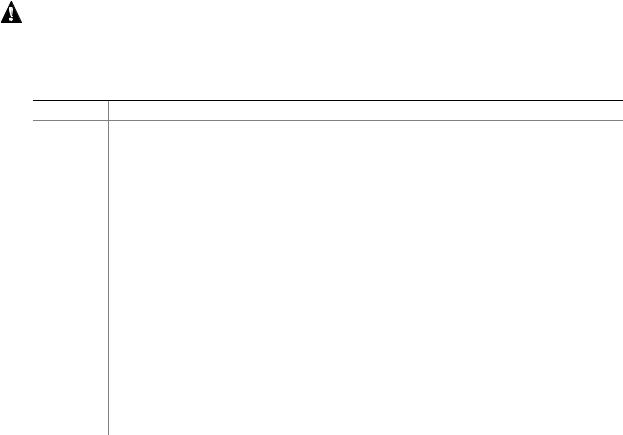
Figure 1 shows the location of the major components on the Desktop Board D925XCV.
A |
B C D E |
|
F G H |
I |
J |
|
|
||
MM |
|
|
|
|
|
|
|
|
K |
|
|
|
|
|
|
|
|
|
L |
|
|
|
|
|
|
|
|
|
M |
LL |
|
|
|
|
|
|
|
|
|
KK |
|
|
|
|
|
|
|
|
|
JJ |
|
|
|
|
|
|
|
|
M |
II |
|
|
|
|
|
|
|
|
|
|
|
|
|
|
|
|
|
O |
|
|
|
|
|
|
|
|
|
|
|
HH |
|
|
|
|
|
|
|
|
P |
|
|
|
|
|
|
|
|
|
|
GG |
|
|
|
|
|
|
|
|
Q |
FF |
|
|
|
|
|
|
|
|
|
|
|
|
|
|
|
|
|
|
|
EE |
|
|
|
|
|
|
|
|
|
|
DD |
BB |
Z |
|
X |
|
|
|
|
|
CC |
|
AA |
Y |
W V |
U |
T |
S |
R |
|
|
|
|
|
|
|
|
|
OM16676 |
Figure 1. Desktop Board D925XCV Components
Table 4 lists the D925XCV components identified in Figure 1.
14
Product Description
Table 4. D925XCV Components Shown in Figure 1.
Item/callout from Figure 1 |
Description |
|
|
A |
Auxiliary rear fan connector |
|
|
B |
ATAPI CD-ROM connector |
|
|
C |
PCI Express x1 bus add-in card connectors |
|
|
D |
Audio codec |
|
|
E |
Front panel audio connector |
|
|
F |
PCI Conventional bus add-in card connectors |
|
|
G |
Marvell Yukon 88E8050 PCI Express Gigabit Ethernet Controller |
|
|
H |
PCI Express x16 bus add-in card connector |
|
|
I |
Rear chassis fan connector |
|
|
J |
Back panel connectors |
|
|
K |
Alternate power connector |
|
|
L |
+12V power connector (ATX12V) |
|
|
M |
LGA775 processor socket |
|
|
N |
Processor fan connector |
|
|
O |
Intel 82925X MCH |
|
|
P |
DIMM Channel A sockets |
|
|
Q |
DIMM Channel B sockets |
|
|
R |
I/O controller |
|
|
S |
Power connector |
|
|
T |
Diskette drive connector |
|
|
U |
Parallel ATE IDE connector |
|
|
V |
Battery |
|
|
W |
Chassis intrusion connector |
|
|
X |
BIOS Setup configuration jumper block |
|
|
Y |
8 Mbit Firmware Hub (FWH) |
|
|
Z |
Front chassis fan connector |
|
|
AA |
Serial ATA connectors |
|
|
BB |
Auxiliary front panel power LED connector |
|
|
CC |
Front panel connector |
|
|
DD |
SCSI hard drive indicator LED (optional) |
|
|
EE |
Auxiliary power output connector (optional) |
|
|
FF |
Front panel USB connector |
|
|
GG |
TPM component (optional) |
|
|
HH |
Front panel USB connector |
|
|
II |
Intel 82801FR I/O Controller Hub (ICH6-R) |
|
|
JJ |
Front panel IEEE-1394a connectors (optional) |
|
|
KK |
IEEE-1394a controller (optional) |
|
|
LL |
Speaker |
|
|
MM |
PCI Conventional bus add-in card connectors |
|
|
15
Intel Desktop Board D925XCV/D925XBC Technical Product Specification
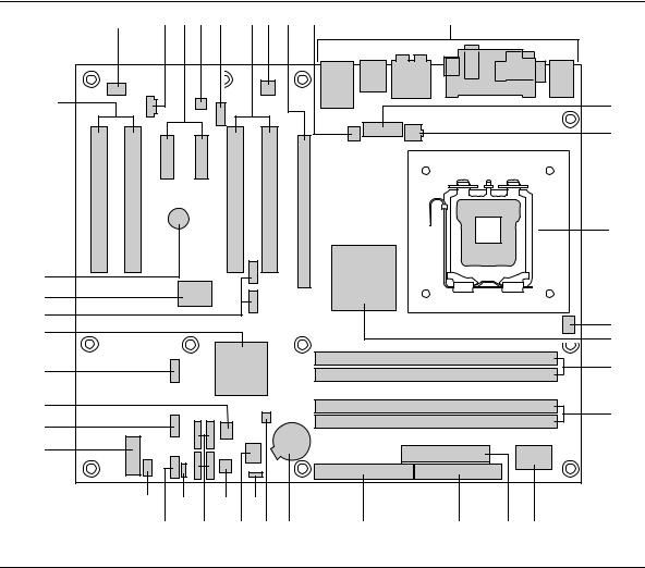
Figure 2 shows the location of the major components on the Desktop Board D925XBC.
|
A B |
|
C D E |
F |
G |
|
|
|
|
|
|
|
|
|
|
|
H |
|
|
|
|
|
|
|
|
I |
HH |
|
|
|
|
|
|
|
|
GG |
|
|
|
|
|
|
|
|
FF |
|
|
|
|
|
|
|
J |
|
|
|
|
|
|
|
|
|
EE |
|
|
|
|
|
|
|
|
DD |
|
|
|
|
|
|
|
K |
CC |
|
|
|
|
|
|
|
|
|
|
|
|
|
|
|
L |
|
|
|
|
|
|
|
|
|
|
BB |
|
|
|
|
|
|
|
M |
|
|
|
|
|
|
|
|
|
AA |
|
|
|
|
|
|
|
N |
|
|
|
|
|
|
|
|
|
Z |
|
|
|
|
|
|
|
|
Y |
W |
|
U |
|
|
|
|
|
|
X |
V |
T |
S |
R |
Q |
P |
O |
|
|
|
|
|
|
|
|
OM16686 |
Figure 2. Desktop Board D925XBC Components
Table 5 lists the D925XCV components identified in Figure 2.
16
Product Description
Table 5. D925XBC Components Shown in Figure 2.
Item/callout from Figure 2 |
Description |
|
|
A |
Audio codec |
|
|
B |
Front panel audio connector |
|
|
C |
PCI Conventional bus add-in card connectors |
|
|
D |
Marvell Yukon 88E8050 PCI Express Gigabit Ethernet Controller |
|
|
E |
PCI Express x16 bus add-in card connector |
|
|
F |
Rear chassis fan connector |
|
|
G |
Back panel connectors |
|
|
H |
Alternate power connector |
|
|
I |
+12V power connector (ATX12V) |
|
|
J |
LGA775 processor socket |
|
|
K |
Processor fan connector |
|
|
L |
Intel 82925X MCH |
|
|
M |
DIMM Channel A sockets |
|
|
N |
DIMM Channel B sockets |
|
|
O |
I/O controller |
|
|
P |
Power connector |
|
|
Q |
Diskette drive connector |
|
|
R |
Parallel ATE IDE connector |
|
|
S |
Battery |
|
|
T |
Chassis intrusion connector |
|
|
U |
BIOS Setup configuration jumper block |
|
|
V |
8 Mbit Firmware Hub (FWH) |
|
|
W |
Front chassis fan connector |
|
|
X |
Serial ATA connectors |
|
|
Y |
Auxiliary front panel power LED connector |
|
|
Z |
Front panel connector |
|
|
AA |
Front panel USB connector |
|
|
BB |
Front panel USB connector |
|
|
CC |
Intel 82801FR I/O Controller Hub (ICH6-R) |
|
|
DD |
Front panel IEEE-1394a connectors (optional) |
|
|
EE |
IEEE-1394a controller (optional) |
|
|
FF |
Speaker |
|
|
GG |
ATAPI CD-ROM connector |
|
|
HH |
PCI Express x1 bus add-in card connector |
|
|
17

Intel Desktop Board D925XCV/D925XBC Technical Product Specification
1.3.4Block Diagram
Figure 3 is a block diagram of the major functional areas of the boards.
|
PCI Express x1 Interface |
|
|
Gigabit Ethernet |
LAN |
||
|
|
|
Controller |
Connector |
|||
|
|
|
|
|
|||
PCI Express x1 Slot 1 |
|
|
|
|
|
Back Panel/Front Panel |
|
|
|
|
|
|
USB |
||
PCI Express x1 Slot 2 |
D925XCV |
|
|
|
|
USB Ports |
|
|
|
|
|
|
|||
|
only |
|
|
|
|
|
|
|
|
|
|
|
LPC Bus |
|
Serial Ports |
Parallel ATA |
Parallel ATA |
|
|
|
Parallel Port |
||
|
|
I/O |
|
||||
|
|
|
PS/2 Mouse |
||||
IDE Connector |
IDE Interface |
|
|
Controller |
|
||
|
|
|
|
|
|
|
PS/2 Keyboard |
LGA775 |
System Bus |
|
|
|
|
|
Diskette Drive |
Processor Socket |
(800/533 MHz) |
|
|
|
|
|
Connector |
|
|
|
|
|
LPC Bus |
|
|
PCI Express |
|
|
Interconnect |
|
|
|
|
x16 Interface |
Intel 82925X |
Intel 82801FR |
|
8 Mbit |
|||
|
|
||||||
|
Memory Controller |
I/O Controller Hub |
|
Firmware Hub |
|||
PCI Express |
Hub (MCH) |
(ICH6-R) |
|
(FWH) |
|||
x16 |
|
|
DMI |
|
|
|
|
Connector |
|
|
|
|
Bus |
Intel 925X Chipset |
|
|
|
|
|
|
|||
|
|
|
|
|
|
||
Dual-Channel |
|
|
|
|
LPC |
TPM Component |
|
Channel A |
Memory Bus |
|
|
|
|
|
|
|
|
|
|
|
(Optional) |
||
SMBus |
|
|
|
|
|||
DIMMs (2) |
|
Link |
|
|
|
||
Channel B |
|
|
|
Serial ATA |
Serial ATA IDE |
||
|
|
|
Audio |
||||
|
|
|
IDE Interface |
Connectors (4) |
|||
DIMMs (2) |
|
|
|
||||
|
|
|
|
|
|
||
|
|
|
|
|
|
|
|
IEEE-1394a Connectors |
|
|
Definition |
Front Panel Retasking Jack A/E |
|||
PCI Bus |
|
Front Panel Retasking Jack F |
|||||
(Optional) |
|
|
|
High |
|||
|
|
|
|
|
|
|
|
|
PCI Bus |
|
|
|
|
Mic In/Retasking Jack B |
|
PCI Slot 1 |
|
|
|
|
|
Line In/Retasking Jack C |
|
|
|
|
|
Audio |
|
|
|
|
|
|
|
|
Line Out/Retasking Jack D |
||
PCI Slot 2 |
SMBus |
|
|
Codec |
|||
|
|
|
|
||||
PCI Slot 3 |
|
|
|
|
|
|
CD-ROM |
|
|
|
|
|
|
|
|
D925XCV |
Hardware Monitoring |
|
|
|
S/PDIF |
||
PCI Slot 4 |
only |
|
|
|
|||
|
|
|
|
||||
|
|
and Fan Control ASIC |
|
|
|
|
|
 Center and LFE/Retasking Jack G
= connector or socket |
|
Surround Left-Right/Retasking Jack H |
|
|
|
||
|
OM16999 |
||
|
|
||
Figure 3. Block Diagram
18

Product Description
1.4 Online Support
To find information about… |
Visit this World Wide Web site: |
Intel Desktop Boards D925XCV and |
http://www.intel.com/design/motherbd |
D925XBC under “Desktop Board |
|
Products” or “Desktop Board Support” |
http://support.intel.com/support/motherboards/desktop |
|
|
Available configurations for the Desktop |
http://developer.intel.com/design/motherbd/cv/cv_available.htm |
Board D925XCV |
|
|
|
Available configurations for the Desktop |
http://developer.intel.com/design/motherbd/bc/bc_available.htm |
Board D925XBC |
|
|
|
Processor data sheets |
http://www.intel.com/design/litcentr |
|
|
ICH6-R addressing |
http://developer.intel.com/design/chipsets/datashts |
|
|
Custom splash screens |
http://intel.com/design/motherbd/gen_indx.htm |
|
|
Audio software and utilities |
http://www.intel.com/design/motherbd |
|
|
LAN software and drivers |
http://www.intel.com/design/motherbd |
|
|
1.5 Processor
The boards are designed to support Intel Pentium 4 processors in an LGA775 processor socket with an 800 or 533 MHz system bus. See the Intel web site listed below for the most up-to-date list of supported processors.
For information about… |
Refer to: |
Supported processors for the D925XCV board |
http://www.intel.com/design/motherbd/cv/cv_proc.htm |
|
|
Supported processors for the D925XBC board |
http://www.intel.com/design/motherbd/bc/bc_proc.htm |
|
|
CAUTION
Use only the processors listed on web site above. Use of unsupported processors can damage the board, the processor, and the power supply.
INTEGRATOR’S NOTES
Use only ATX12V-compliant power supplies.
For information about |
Refer to |
Power supply connectors |
Section 2.8.1.1, page 64 |
|
|
19
Intel Desktop Board D925XCV/D925XBC Technical Product Specification
1.6 System Memory
The boards have four DIMM sockets and support the following memory features:
•1.8 V (only) DDR2 SDRAM DIMMs
•Unbuffered, single-sided or double-sided DIMMs with the following restriction: Double-sided DIMMS with x16 organization are not supported.
•4 GB maximum total system memory. Refer to Section 2.2.1 on page 55 for information on the total amount of addressable memory.
•Minimum total system memory: 128 MB
•Non-ECC DIMMs
•Serial Presence Detect
•DDR2 533 MHz or DDR2 400 MHz SDRAM DIMMs
NOTES
•Remove the PCI Express x16 video card before installing or upgrading memory to avoid interference with the memory retention mechanism.
•To be fully compliant with all applicable DDR SDRAM memory specifications, the board should be populated with DIMMs that support the Serial Presence Detect (SPD) data structure. This allows the BIOS to read the SPD data and program the chipset to accurately configure memory settings for optimum performance. If non-SPD memory is installed, the BIOS will attempt to correctly configure the memory settings, but performance and reliability may be impacted or the DIMMs may not function under the determined frequency.
Table 6 lists the supported DIMM configurations.
Table 6. |
Supported Memory Configurations |
|
|||
|
|
|
|
|
|
DIMM |
|
|
SDRAM |
SDRAM Organization |
Number of SDRAM |
Capacity |
|
Configuration |
Density |
Front-side/Back-side |
Devices |
|
|
|
|
|
|
128 MB |
|
SS |
256 Mbit |
16 M x 16/empty |
4 |
|
|
|
|
|
|
256 MB |
|
SS |
256 Mbit |
32 M x 8/empty |
8 |
|
|
|
|
|
|
256 MB |
|
SS |
512 Mbit |
32 M x 16/empty |
4 |
|
|
|
|
|
|
512 MB |
|
DS |
256 Mbit |
32 M x 8/32 M x 8 |
16 |
|
|
|
|
|
|
512 MB |
|
SS |
512 Mbit |
64 M x 8/empty |
8 |
|
|
|
|
|
|
512 MB |
|
SS |
1 Gbit |
64 M x 16/empty |
4 |
|
|
|
|
|
|
1024 MB |
|
DS |
512 Mbit |
64 M x 8/64 M x 8 |
16 |
|
|
|
|
|
|
1024 MB |
|
SS |
1 Gbit |
128 M x 8/empty |
8 |
|
|
|
|
|
|
2048 MB |
|
DS |
1 Gbit |
128 M x 8/128 M x 8 |
16 |
|
|
|
|
|
|
Note: In the second column, “DS” refers to double-sided memory modules (containing two rows of SDRAM) and “SS” refers to single-sided memory modules (containing one row of SDRAM).
INTEGRATOR’S NOTE
Refer to Section 2.2.1, on page 55 for additional information on available memory.
20
Product Description
1.6.1Memory Configurations
The Intel 82925X MCH supports two types of memory organization:
•Dual channel (Interleaved) mode. This mode offers the highest throughput for real world applications. Dual channel mode is enabled when the installed memory capacities of both DIMM channels are equal. Technology and device width can vary from one channel to the other but the installed memory capacity for each channel must be equal. If different speed DIMMs are used between channels, the slowest memory timing will be used.
•Single channel (Asymmetric) mode. This mode is equivalent to single channel bandwidth operation for real world applications. This mode is used when only a single DIMM is installed or the memory capacities are unequal. Technology and device width can vary from one channel to the other. If different speed DIMMs are used between channels, the slowest memory timing will be used.
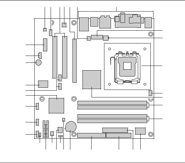
Figure 4 illustrates the memory channel and DIMM configuration.
NOTE
The DIMM0 sockets of both channels are blue. The DIMM1 sockets of both channels are black.
Channel A, DIMM 0 |
Channel A, DIMM 1 |
Channel B, DIMM 0 |
Channel B, DIMM 1 |
OM16677 |
Figure 4. Memory Channel and DIMM Configuration
21
Intel Desktop Board D925XCV/D925XBC Technical Product Specification
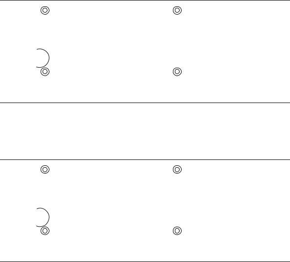
1.6.1.1Dual Channel (Interleaved) Mode Configurations
Figure 5 shows a dual channel configuration using two DIMMs. In this example, the DIMM0 (blue) sockets of both channels are populated with identical DIMMs.
|
|
|
|
|
|
|
|
|
|
|
|
Channel A, DIMM 0 |
|
|
|
1 GB |
|
|
|
||||||
|
|
|
|
|
|
|||||||
|
|
|
|
|
|
|
|
|
|
|
|
Channel A, DIMM 1 |
|
|
|
|
|
|
|
|
|
|
|
|
|
|
|
|
|
|
|
|
|
|
|
|
|
|
|
|
|
|
|
|
|
|
|
|
|
||
|
|
|
|
|
|
|
|
|
|
Channel B, DIMM 0 |
||
|
|
|
1 GB |
|
|
|
||||||
|
|
|
|
|
|
|
||||||
|
|
|
|
|
|
|
|
|
|
|
|
Channel B, DIMM 1 |
|
|
|
|
|
|
|
|
|
|
|
|
|
|
|
|
|
|
|
|
|
|
|
|
|
|
|
|
|
|
|
|
|
|
|
|
|
||
|
|
|
|
|
|
|
|
|
|
|
|
|
|
|
|
|
|
|
|
|
|
|
|
|
|
|
|
|
|
|
|
|
|
|
|
|
|
|
|
|
|
|
|
|
|
|
|
|
|
|
|
|
|
|
|
|
|
|
|
|
|
|
|
|
OM17123
Figure 5. Dual Channel (Interleaved) Mode Configuration with Two DIMMs
Figure 6 shows a dual channel configuration using three DIMMs. In this example, the combined capacity of the two DIMMs in Channel A equal the capacity of the single DIMM in the DIMM0 (blue) socket of Channel B.
|
|
|
|
|
|
|
|
|
|
|
|
Channel A, DIMM 0 |
|
|
|
256 MB |
|
|
|||||||
|
|
|
|
|
||||||||
|
|
|
|
|
|
|
|
|
|
|
|
|
|
|
|
256 MB |
|
|
|
Channel A, DIMM 1 |
|||||
|
|
|
|
|
|
|
|
|
|
|
||
|
|
|
|
|
|
|
|
|
|
|
||
|
|
|
|
|
|
|
|
|
|
|
Channel B, DIMM 0 |
|
|
|
|
512 MB |
|
|
|||||||
|
|
|
|
|
|
|||||||
|
|
|
|
|
|
|
|
|
|
|
|
Channel B, DIMM 1 |
|
|
|
|
|
|
|
|
|
|
|
|
|
|
|
|
|
|
|
|
|
|
|
|
|
|
|
|
|
|
|
|
|
|
|
|
|
||
|
|
|
|
|
|
|
|
|
|
|
|
|
|
|
|
|
|
|
|
|
|
|
|
|
|
|
|
|
|
|
|
|
|
|
|
|
|
|
|
|
|
|
|
|
|
|
|
|
|
|
|
|
|
|
|
|
|
|
|
|
|
|
|
|
OM17122
Figure 6. Dual Channel (Interleaved) Mode Configuration with Three DIMMs
22

Product Description
Figure 7 shows a dual channel configuration using four DIMMs. In this example, the combined capacity of the two DIMMs in Channel A equal the combined capacity of the two DIMMs in Channel B. Also, the DIMMs are matched between DIMM0 and DIMM1 of both channels.
|
|
|
|
|
|
|
|
|
|
|
|
Channel A, DIMM 0 |
|
|
|
256 MB |
|
|
|||||||
|
|
|
|
|
||||||||
|
|
|
|
|
|
|
|
|
|
|
|
|
|
|
|
512 MB |
|
|
|
Channel A, DIMM 1 |
|||||
|
|
|
|
|
|
|
|
|
|
|
||
|
|
|
|
|
|
|
|
|
|
|
||
|
|
|
|
|
|
|
|
|
|
|
Channel B, DIMM 0 |
|
|
|
|
256 MB |
|
|
|||||||
|
|
|
|
|
|
|||||||
|
|
|
|
|
|
|
|
|
|
|
|
|
|
|
|
512 MB |
|
|
|
Channel B, DIMM 1 |
|||||
|
|
|
|
|
|
|
|
|
|
|
||
|
|
|
|
|
|
|
|
|
|
|
||
|
|
|
|
|
|
|
|
|
|
|
|
|
|
|
|
|
|
|
|
|
|
|
|
|
|
|
|
|
|
|
|
|
|
|
|
|
|
|
|
|
|
|
|
|
|
|
|
|
|
|
|
|
|
|
|
|
|
|
|
|
|
|
|
|
OM17124
Figure 7. Dual Channel (Interleaved) Mode Configuration with Four DIMMs
23

Intel Desktop Board D925XCV/D925XBC Technical Product Specification
1.6.1.2Single Channel (Asymmetric) Mode Configurations
NOTE
Dual channel (Interleaved) mode configurations provide the highest memory throughput.
Figure 8 shows a single channel configuration using one DIMM. In this example, only the DIMM0 (blue) socket of Channel A is populated. Channel B is not populated.
|
|
|
|
|
|
|
|
|
|
|
Channel A, DIMM 0 |
|
|
|
256 MB |
|
|
|
|||||
|
|
|
|
|
|
||||||
|
|
|
|
|
|
|
|
|
|
|
Channel A, DIMM 1 |
|
|
|
|
|
|
|
|
|
|
|
|
|
|
|
|
|
|
|
|
|
|
|
|
|
|
|
|
|
|
|
|
|
|
||
|
|
|
|
|
|
|
|
|
|
|
Channel B, DIMM 0 |
|
|
|
|
|
|
|
|
|
|
||
|
|
|
|
|
|
|
|
|
|
|
|
|
|
|
|
|
|
|
|
|
|
|
Channel B, DIMM 1 |
|
|
|
|
|
|
|
|
|
|
|
|
|
|
|
|
|
|
|
|
|
|
|
|
|
|
|
|
|
|
|
|
|
|
||
|
|
|
|
|
|
|
|
|
|
|
|
|
|
|
|
|
|
|
|
|
|
|
|
|
|
|
|
|
|
|
|
|
|
|
|
|
|
|
|
|
|
|
|
|
|
|
|
|
|
|
|
|
|
|
|
|
|
|
|
OM17125
Figure 8. Single Channel (Asymmetric) Mode Configuration with One DIMM
Figure 9 shows a single channel configuration using three DIMMs. In this example, the combined capacity of the two DIMMs in Channel A does not equal the capacity of the single DIMM in the DIMM0 (blue) socket of Channel B.
|
|
|
|
|
|
|
|
|
|
|
|
Channel A, DIMM 0 |
|
|
|
256 MB |
|
|
|||||||
|
|
|
|
|
||||||||
|
|
|
|
|
|
|
|
|
|
|
|
|
|
|
|
512 MB |
|
|
|
Channel A, DIMM 1 |
|||||
|
|
|
|
|
|
|
|
|
|
|
||
|
|
|
|
|
|
|
|
|
|
|
||
|
|
|
|
|
|
|
|
|
|
|
Channel B, DIMM 0 |
|
|
|
|
512 MB |
|
|
|||||||
|
|
|
|
|
|
|||||||
|
|
|
|
|
|
|
|
|
|
|
|
Channel B, DIMM 1 |
|
|
|
|
|
|
|
|
|
|
|
|
|
|
|
|
|
|
|
|
|
|
|
|
|
|
|
|
|
|
|
|
|
|
|
|
|
||
|
|
|
|
|
|
|
|
|
|
|
|
|
|
|
|
|
|
|
|
|
|
|
|
|
|
|
|
|
|
|
|
|
|
|
|
|
|
|
|
|
|
|
|
|
|
|
|
|
|
|
|
|
|
|
|
|
|
|
|
|
|
|
|
|
OM17126
Figure 9. Single Channel (Asymmetric) Mode Configuration with Three DIMMs
24
Product Description
1.7 Intel® 925X Chipset
The Intel 925X chipset consists of the following devices:
•Intel 82925X Memory Controller Hub (MCH) with Direct Media Interface (DMI) interconnect
•Intel 82801FR I/O Controller Hub (ICH6-R) with DMI interconnect
•Firmware Hub (FWH)
The MCH is a centralized controller for the system bus, the memory bus, the PCI Express bus, and the DMI interconnect. The ICH6-R is a centralized controller for the board’s I/O paths. The FWH provides the nonvolatile storage of the BIOS.
For information about |
Refer to |
The Intel 925X chipset |
http://developer.intel.com/ |
|
|
Resources used by the chipset |
Chapter 2 |
|
|
1.7.1USB
The boards support up to eight USB 2.0 ports, supports UHCI and EHCI, and uses UHCIand EHCI-compatible drivers.
The ICH6-R provides the USB controller for all ports. The port arrangement is as follows:
•Four ports are implemented with dual stacked back panel connectors adjacent to the audio connectors
•Four ports are routed to two separate front panel USB connectors
NOTES
•Computer systems that have an unshielded cable attached to a USB port may not meet FCC Class B requirements, even if no device is attached to the cable. Use shielded cable that meets the requirements for full-speed devices.
For information about |
Refer to |
The location of the USB connectors on the back panel |
Figure 20, page 66 |
|
|
The location of the front panel USB connectors on the Desktop Board D925XCV |
Figure 21, page 68 |
|
|
The location of the front panel USB connectors on the Desktop Board D925XBC |
Figure 22, page 70 |
|
|
1.7.2IDE Support
The board provides five IDE interface connectors:
•One parallel ATA IDE connector, which supports two devices
•Four serial ATA IDE connectors, which support one device per connector
1.7.2.1Parallel ATE IDE Interface
The ICH6-R’s Parallel ATA IDE controller has one bus-mastering Parallel ATA IDE interface. The Parallel ATA IDE interface supports the following modes:
•Programmed I/O (PIO): processor controls data transfer.
•8237-style DMA: DMA offloads the processor, supporting transfer rates of up to 16 MB/sec.
25
Intel Desktop Board D925XCV/D925XBC Technical Product Specification
•Ultra DMA: DMA protocol on IDE bus supporting host and target throttling and transfer rates of up to 33 MB/sec.
•ATA-66: DMA protocol on IDE bus supporting host and target throttling and transfer rates of up to 66 MB/sec. ATA-66 protocol is similar to Ultra DMA and is device driver compatible.
•ATA-100: DMA protocol on IDE bus allows host and target throttling. The ICH6-R’s ATA-100 logic can achieve read transfer rates up to 100 MB/sec and write transfer rates up to 88 MB/sec.
NOTE
ATA-66 and ATA-100 are faster timings and require a specialized cable to reduce reflections, noise, and inductive coupling.
The Parallel ATA IDE interface also supports ATAPI devices (such as CD-ROM drives) and ATA devices using the transfer modes.
The BIOS supports Logical Block Addressing (LBA) and Extended Cylinder Head Sector (ECHS) translation modes. The drive reports the transfer rate and translation mode to the BIOS.
The boards support Laser Servo (LS-120) diskette technology through the Parallel ATA IDE interfaces. An LS-120 drive can be configured as a boot device by setting the BIOS Setup program’s Boot menu to one of the following:
•ARMD-FDD (ATAPI removable media device – floppy disk drive)
•ARMD-HDD (ATAPI removable media device – hard disk drive)
For information about |
Refer to |
The location of the Parallel ATA IDE connector on the D925XCV board |
Figure 21, page 68 |
|
|
The location of the Parallel ATA IDE connector on the D925XBC board |
Figure 22, page 70 |
|
|
1.7.2.2Serial ATA Interfaces
The ICH6-R’s Serial ATA controller offers four independent Serial ATA ports with a theoretical maximum transfer rate of 150 MB/s per port. One device can be installed on each port for a maximum of four Serial ATA devices. A point-to-point interface is used for host to device connections, unlike Parallel ATA IDE which supports a master/slave configuration and two devices per channel.
For compatibility, the underlying Serial ATA functionality is transparent to the operating system. The Serial ATA controller can operate in both legacy and native modes. In legacy mode, standard IDE I/O and IRQ resources are assigned (IRQ 14 and 15). In Native mode, standard PCI Conventional bus resource steering is used. Native mode is the preferred mode for configurations using the Windows XP and Windows 2000 operating systems.
NOTE
Many Serial ATA drives use new low-voltage power connectors and require adaptors or power supplies equipped with low-voltage power connectors.
For more information, see: http://www.serialata.org/
26
Product Description
For information about |
Refer to |
The location of the Serial ATA IDE connectors on the D925XCV board |
Figure 21, page 68 |
|
|
The location of the Serial ATA IDE connectors on the D925XBC board |
Figure 22, page 70 |
|
|
1.7.2.3Serial ATA RAID
The ICH6-R supports RAID (Redundant Array of Independent Drives) level 0 and RAID level 1 on the Serial ATA ports as follows:
•RAID 0 supports data striping. Two physical drives, of identical size, can be teamed together to create one logical drive. As data is written or retrieved from the logical drive, both drives operate in parallel, thus increasing the throughput.
•RAID 1 supports data mirroring. Two physical drives, of identical size, maintain duplicate sets of all data on separate disk drives. Level 1 provides the highest data reliability because two complete copies of all information are maintained.
1.7.2.4RAID Boot Configuration Overview
A RAID array can be created by using the existing Serial ATA ports, correctly configuring the BIOS, and installing drivers. The following steps are required to successfully establish a RAID configuration.
1.Enable RAID Support in BIOS.
2.Create a RAID array using the Intel Application Accelerator (IAA) utility.
3.Install the IAA RAID driver.
4.Format the RAID array.
5.Install the IAA Companion Utility (this step is optional).
For information about |
Refer to |
Serial ATA RAID configuration |
http://developer.intel.com/design/motherbd/cv/index.htm |
|
|
1.7.2.5SCSI Hard Drive Activity LED Connector (Optional)
The SCSI hard drive activity LED connector is a 1 x 2-pin connector that allows an add-in
hard drive controller to use the same LED as the onboard IDE controller. For proper operation, this connector should be wired to the LED output of the add-in hard drive controller. The LED indicates when data is being read from, or written to, either the add-in hard drive controller or the onboard IDE controller (Parallel ATA or Serial ATA).
NOTE
The SCSI Hard Drive Activity LED connector is an option available only on the D925XCV board. It is not available on the D925XBC board.
For information about |
Refer to |
The location of the SCSI hard drive activity LED connector on the |
Figure 21, page 68 |
D925XCV board |
|
|
|
The signal names of the SCSI hard drive activity LED connector |
Table 26, page 73 |
|
|
27
Intel Desktop Board D925XCV/D925XBC Technical Product Specification
1.7.3Real-Time Clock, CMOS SRAM, and Battery
A coin-cell battery (CR2032) powers the real-time clock and CMOS memory. When the computer is not plugged into a wall socket, the battery has an estimated life of three years. When the computer is plugged in, the standby current from the power supply extends the life of the battery. The clock is accurate to ± 13 minutes/year at 25 ºC with 3.3 VSB applied.
NOTE
If the battery and AC power fail, custom defaults, if previously saved, will be loaded into CMOS RAM at power-on.
1.8 PCI Express Connectors
The boards provide the following PCI Express connectors:
•One PCI Express x16 connector. The x16 interface supports simultaneous (full duplex) transfer speeds up to 8 GBytes/sec. Single-ended (half duplex) transfers are supported at up to
4 Gbytes/sec.
•Four PCI Express x1 connectors on the D925XCV board; two PCI Express x1 connectors on the D925XBC board. The x1 interfaces support simultaneous transfer speeds up to
500 MBytes/sec
The PCI Express interface supports the PCI Conventional bus configuration mechanism so that the underlying PCI Express architecture is compatible with PCI Conventional compliant operating systems. Additional features of the PCI Express interface includes the following:
•Support for the PCI Express enhanced configuration mechanism
•Automatic discovery, link training, and initialization
•Support for Active State Power Management (ASPM)
•SMBus 2.0 support
•Wake# signal supporting wake events from ACPI S1, S3, S4, or S5
•Software compatible with the PCI Power Management Event (PME) mechanism defined in the PCI Power Management Specification Rev. 1.1
1.9Auxiliary Power (AUX PWR) Output Connector
The D925XCV board includes a 1x4 power connector that can be used to provide power for internal chassis lighting or additional fans. The use of this connector requires an ATX12V power supply with a 24-pin (2x12) main power cable. If a power supply with a 20-pin (2x10) main power cable is used, the auxiliary power output connector may not function.
The on/off function of this connector is controlled from within the BIOS Setup Program. The default setting in the BIOS is for this connector to be off.
28
Product Description
INTEGRATOR’S NOTES
When using this connector, observe the following precautions:
•Do not use a Y-adapter, power splitter, or SATA power adapter to attach storage devices (such as hard disk drives or CD/DVD drives) to this connector. This connector will not provide adequate power for storage devices.
•Do not connect any devices to this connector that draw more than 1.5 A. The connector circuitry includes overcurrent protection components that limit the current draw to a maximum of 1.5 A.
For information about |
Refer to |
The location of the auxiliary power output connector |
Figure 21, page 68 |
|
|
The signal names of the auxiliary power output connector |
Table 28, page 73 |
|
|
NOTE
The auxiliary power output connector is present only on the D925XCV board. It is not present on the D925XBC board.
1.10 I/O Controller
The I/O controller provides the following features:
•One serial port
•One parallel port with Extended Capabilities Port (ECP) and Enhanced Parallel Port (EPP) support
•Serial IRQ interface compatible with serialized IRQ support for PCI Conventional bus systems
•PS/2-style mouse and keyboard interfaces
•Interface for one 1.44 MB or 2.88 MB diskette drive
•Intelligent power management, including a programmable wake-up event interface
•PCI Conventional bus power management support
The BIOS Setup program provides configuration options for the I/O controller.
1.10.1Serial Port
The boards have one serial port connector located on the back panel. The serial port supports data transfers at speeds up to 115.2 kbits/sec with BIOS support.
For information about |
Refer to |
The location of the serial port A connector |
Figure 20, page 66 |
|
|
1.10.2Parallel Port
The 25-pin D-Sub parallel port connector is located on the back panel. Use the BIOS Setup program to set the parallel port mode.
29
Intel Desktop Board D925XCV/D925XBC Technical Product Specification
For information about |
Refer to |
The location of the parallel port connector |
Figure 20, page 66 |
|
|
1.10.3Diskette Drive Controller
The I/O controller supports one diskette drive. Use the BIOS Setup program to configure the diskette drive interface.
For information about |
Refer to |
The location of the diskette drive connector on the D925XCV board |
Figure 21, page 68 |
|
|
The location of the diskette drive connector on the D925XBC board |
Figure 22, page 70 |
|
|
1.10.4Keyboard and Mouse Interface
PS/2 keyboard and mouse connectors are located on the back panel.
NOTE
The keyboard is supported in the bottom PS/2 connector and the mouse is supported in the top PS/2 connector. Power to the computer should be turned off before a keyboard or mouse is connected or disconnected.
For information about |
Refer to |
The location of the keyboard and mouse connectors |
Figure 20, page 66 |
|
|
30
Loading...